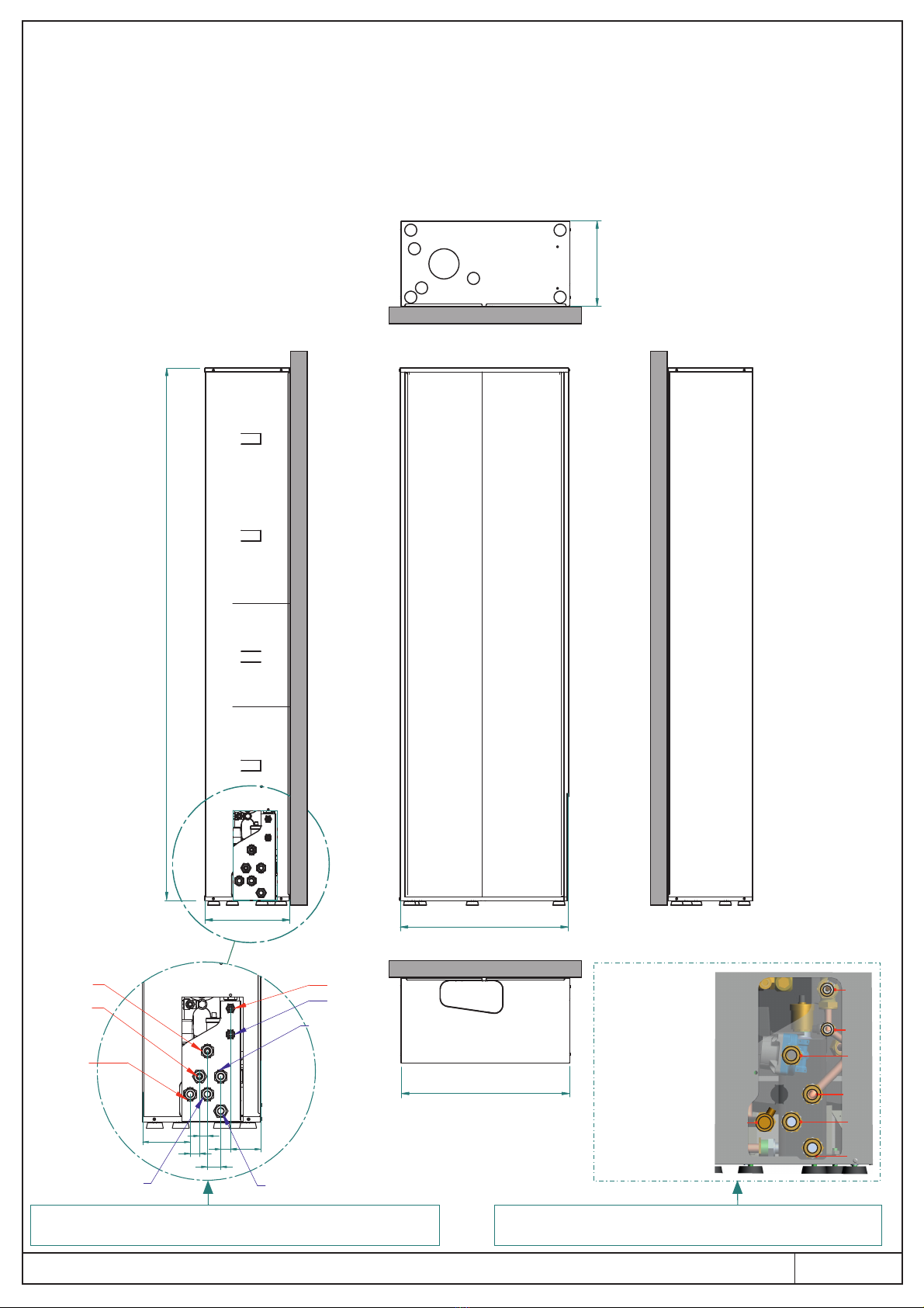
Unical SLIM HP 2.0 User manual

METAL BOX FOR BUILT-IN / WALL INSTALLATION - PAINTED
00338775_ _20212 3 1/8
BOX METALLICO PER INCASSO / VISTA - VERNICIATO
700
350
2200

This unit makes it possible to install parts of the integrated system in indoor or outdoor walls.
t the bottom right, there to pass the pipes through for the connection to the hydraulic system, to the electrical lineA is opening etc
At the top there required to pass the pipes through for the connection to the solar systemis opening .
Descrizione / Description:
Dimensioni / Dimensions:
L'unità da incasso permette l’installazione dei componenti del sistema integrato in pareti esterne o interne.
Essa è dotata nella parte inferiore destra di apertura necessaria per il passaggio dei tubi di allacciamento all'impianto idrico, alla linea elettrica etc.
Nella zona superiore vi sono i fori necessari per il passaggio dei tubi di allacciamento all'impianto solare.
A
350
2020
700
350
9029
40
23
28
141
R.PDC
C
F
M.PDC
R.Z )2 (mix
M.Z )2 (mix
R.Z1
M1.Z
700
2/8
Indicazioni relative ad attacchi per sistema SLIM - SLIMs HP 2.0
Hydraulic connection SLIM - SLIMs HP 2.0
C
F
Mi
Ri
R
Mpdc
Rpdc
Indicazioni relative ad attacchi per sistema / Hydraulic
connection HYBREER SLIM - SLIMs
Configurazione
Parallelo
(per configurazione
Serie vedere
libretto 00339318
pag. 7-8).
Configuration
Parallel
(for configuration
Series see
booklet 00339318
page 7-8).

Composition:
The unit is package in 1 box
- Top cover
- Bottom
- Lh side
- Rh side
Left side- rear back panel
- back panelRight side rear
- with insulationLeft door
- Right door with insulation
- Assembly instructions
- Plastic bag containing:
3.8x9.5 mm self-threading screws
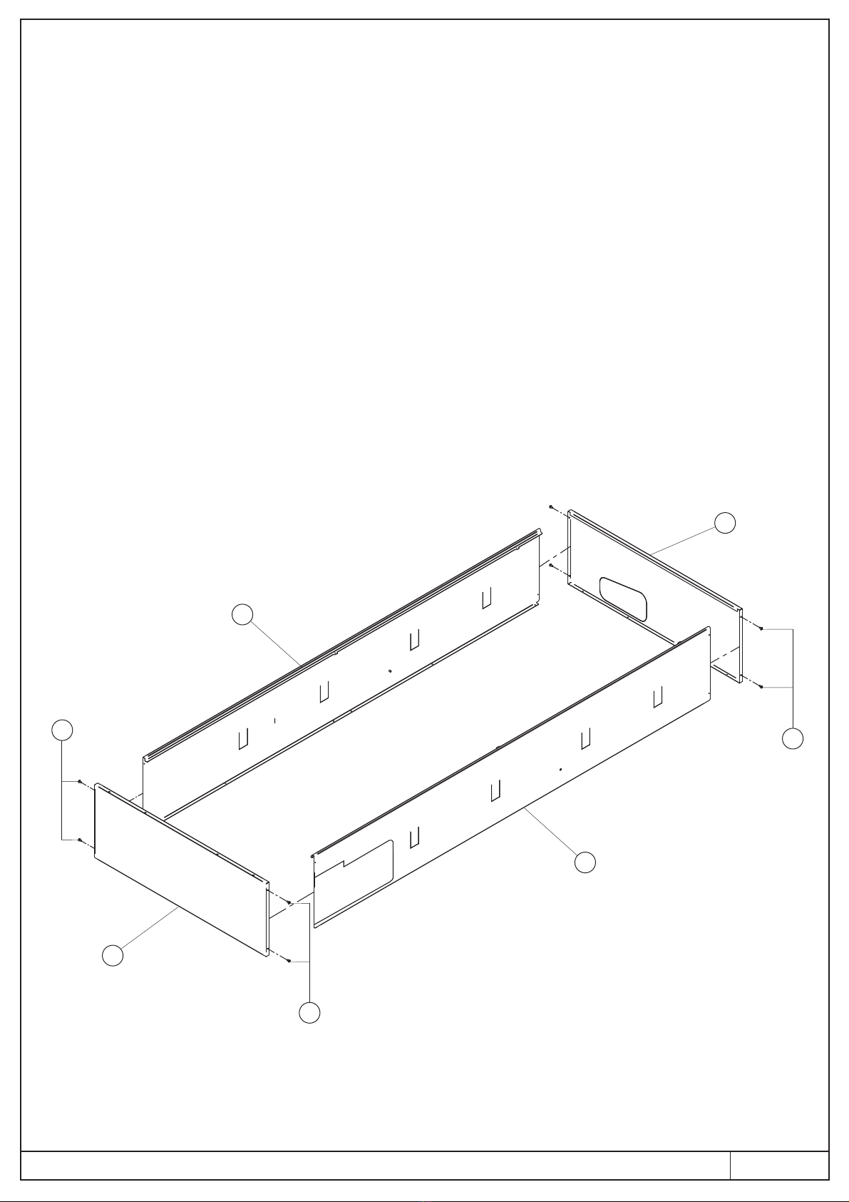
Unit assembly:
Note: Perform assembly on a flat and horizontal surface.
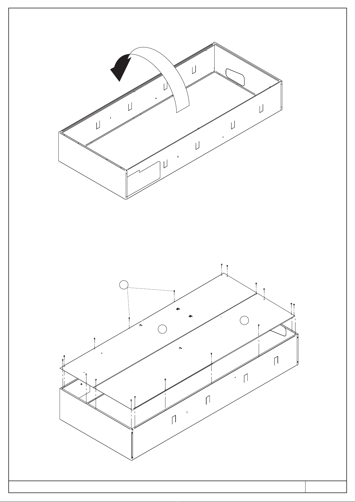
- Secure the bottom (1) to the rh side (2) and to the lh side (5) using the 4 supplied screws (3)
- Secure the top cover (4) to the rh side (2) and to the lh side (5) using the 4 supplied screws (3)
5
2
3
3
3
1
4
3/8
Composizione:
L’unità si compone di n° 1 collo:
- Coperchio superiore
- Fondo
- Fianco Sx
- Fianco Dx
- Schienale posteriore DX
- Schienale posteriore SX
- Porta frontale destra con isolamento
- porta frontale sinistra con isolamento
- Istruzioni di montaggio
- Sacchetto di plastica contenente:
viti autofilettanti 3,8x9,5 mm
Assemblaggio dell’unità:
NB: Effettuare il montaggio su una superficie piana e orizzontale.
- Fissare il fondo (1) al fianco dx (2) e al fianco sx (5) mediante 4 viti (3) fornite a corredo
- Fissare il coperchio superiore (4) al fianco dx (2) e al fianco sx (5) mediante 4 viti (3) fornite a corredo

- Turn the unit's perimeter by 180°
- Secure the back (5) and the back panel (6) to the perimeter using the supplied screws (3)LEFT RIGHT
6
5
3
4/8
- Ruotare di 180° il perimetrale dell’unità
- Fissare lo schienale SINISTRO (5) e lo schienale DESTRO (6) al perimetrale mediante le viti (3) fornite a corredo

Prepare the niche in masonry based on the measurements of the built-in unit, ensuring that it is perfectly square and
plastered according to professional standard.
Prepare:
- eight spaces to place the bracket clamps
- a large enough space to set up the hydraulic and electric connections
- supporting screed under the points where the storage tanks stand
- a perfectly vertical surface with thermal-acoustic insulation on the rear part of the supporting area
a) Built-in installation:
Bracket
clamps
5/8
Predisporre la nicchia in muratura delle dimensioni dell’incasso, assicurandosi che sia in squadro e intonacata
a regola d’arte.
Prevedere:
- otto spacchi per l’inserimento delle zanche
- uno spazio sufficiente per poter effettuare gli allacciamenti idraulici ed elettrici
- un massetto di sostegno in corrispondenza dei punti di appoggio dei bollitori
- un perfetto piano verticale con isolamento termo-acustico nella parte posteriore di appoggio
a) Installazione incassata:

Place the unit in the niche after:
- bending the 8 bracket clamps (9) outwards, pre-cut on the sides
- removing the pre-cuts where the pipes will go
9
6/8
Inserire l’unità nella nicchia dopo aver:
- piegato verso l’esterno le 8 zanche (9) pretranciate sui fianchi
- rimosso la pretranciatura in uscita tubi
Ensure that the built-in unit is level/plumb before building it into the wall
Proceed with setting up the
connections:
- to the water system
- to the solar system
- to safety valve drain
- to the electrical power line
Verificare la messa in bolla/piombo dell’incasso prima di procedere alla
muratura dello stesso
Procedere alla realizzazione degli
allacciamenti:
- all'impianto idrico
- all'impianto solare
- allo scarico delle valvole di sicurezza
- alla linea elettrica

106
84
195 150
700
TOP
CONNECTIONS
DOMESTIC HOT WATER OUTLET
DOMESTIC WATER INLET
FLOW 1 zone
RETURN 1 zone
FLOW HEAT PUMP
RETURN HEAT PUMP
MIXED LOW TEMPERATURE FLO
MIXED LOW TEMPERATURE RE
SOLAR SYSTEM FLOW
SOLAR SYSTEM RETURN
CONNESSIONI
CONNECTIONS
R(is)
M(is)
Connection set-up:
9029
40
23
28
141
R.PDC
C
F
M.PDC
R.Z )2 (mix
M.Z )2 (mix
R.Z1
M1.Z
33,350 53 75 50 77
Legenda / Key
C
F
M(Z1)
R(Z1)
M (PDC)
R (PDC)
M(Z2mix)
R(Z2mix)
M(is)
R(is)
ALLACCIAMENTI
SUPERIORI
USCITA ACQUA CALDA SANITARIO
INGRESSO ACQUA SANITARIO
MANDATA ZONA 1
RITORNO ZONA 1
MANDATA (POMPA DI CALORE)
RITORNO (POMPA DI CALORE)
MANDATA ZONA 2 MISCELATA
RITORNO ZONA 2 MISCELATA
MANDATA IMPIANTO SOLARE
RITORNO IMPIANTO SOLARE
Posizionamento allacciamenti:
7/8
C
F
F = ingresso fredda F da acquedotto
cold in F from aqueduct
Mi Mi = alla mandata impianto (solo
raffrescamento). / to the system delivery
(only cooling).
Ri Ri = da ritorn impianto (riscaldamentoo
/ raffrescamento) / from system return (heating
/ cooling)
R
R = al ritorno caldaia / to the boiler return
Mpdc
Mpdc =
ingresso
mandata
Pompa di
calore.
in
flow
Pump
heat.
Rpdc Rpdc = al ritorno Pompa di calore / on return
Heat pump
C = all’ingresso fredda sanitaria caldaia
at the boiler domestic cold inlet
ATTACCHI IDRAULICI / G = 1’’ ) - G = 1/2’’HYDRAULIC CONNECTIONS (M/R (C/F)
Indicazioni relative ad attacchi per sistema
SLIM - SLIMs HP 2.0
Hydraulic connection SLIM - SLIMs HP 2.0
Indicazioni relative ad attacchi per sistema / Hydraulic
connection HYBREER SLIM - SLIMs
Configurazione
Parallelo
(per configurazione
Serie vedere
libretto 00339318
pag. 7-8).
Configuration
Parallel
(for configuration
Series see
booklet 00339318
page 7-8).

8/8
B) Exposed installation
When choosing the place of installation for the appliance, follow the safety instructions below:
- Place the appliance in rooms protected from frost.
- Avoid installation in rooms with a corrosive or very dusty atmosphere.
- Observe the minimum spaces required for the maintenance operations (installation technician instruction manua)
Secure the 4 supporting feet to the box, as shown,(13)
and then secure the storage tank's other 3 feet (Chap. 3.5.2
Phase 1 storage tank module).
B) Installazione a vista
Nella scelta del luogo di installazione dell'apparecchio attenersi alle seguenti indicazioni di sicurezza:
- Collocare l'apparecchio in locali protetti dal gelo.
- Evitare l'installazione in locali con atmosfera corrosiva o molto polverosa.
- Rispettare quote di rispetto per operazioni i manutenzione (libretto installatore)
Fissare i 4 piedi di appoggio al box come indicato(13)
e successivamente fissare gli altri 3 piedini del bollitore
(Cap. 3.5.2 Fase 1 modulo accumulo).
13
This manual suits for next models
1
Table of contents
Other Unical Chiller manuals
Popular Chiller manuals by other brands

York
York OPTIVIEW YIA D Operation manual

OYL MANUFACTURING COMPANY
OYL MANUFACTURING COMPANY AC040A installation manual

Husky
Husky C Series user manual

Elkay
Elkay HRC2-1C installation instructions

McQuay
McQuay AGZ 010BS Installation, operation and maintenance

York
York YCAV0267E Installation operation & maintenance

Aquacal
Aquacal TropiCool TC500 Operation manual

Trane
Trane CGAH Series Installation operation & maintenance

Liebert
Liebert HPC-S 022 Product documentation

ACS
ACS GP Series Operation and installation manual

Aquaport
Aquaport AQP-BRD User manual & warranty

Carrier
Carrier 30GX Series Installation, operation and maintenance instructions