EN - 2
1 - INTRODUCTION
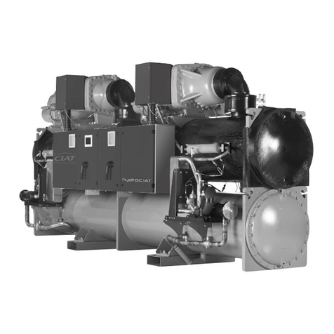
HYDROCIAT water-cooled condensation chilled water
production units, with LW series screw compressors, and
LWP series heat pump, provide the perfect solution to the
problems encountered in the fields of air conditioning or the
industrial process.
These units comply with standards EN 60-204 and EN 378-2,
as well as the following directives:
- Machinery 2006/42 CE
- EMC 2004/108 EC
- LVD 2006/95 EC
- PED 97/23 EC
-> Category 3 models LW - LWP 1800BX (HPS) to 2800BX (HPS)
-> Category 4 models LW - LWP 3050BX (HPS) to 4800BX (HPS)
Test pressure (TP): Test not executed given the
harmfulness of a hydrostatic pressure test. CIAT has set up
compensatory measures (tests on a model representative
of all 3 x PS assemblies) in compliance with § 5.3.2.2 a and
6.3.3 iii of standard 378-2.
Shipment temperature:
LW 1800 to 2800 → Min. -30°C - Max. 50°C.
LW 3050 to 4800 → Min. -30°C - Max. 60°C.
Storage temperature:
LW 1800 to 2800 → Min. -30°C - Max. 50°C.
LW 3050 to 4800 → Min. -30°C - Max. 60°C.
Operating temperature:
Refer to the section on "operating limits" in these instructions.
2 - SHIPMENT OF THE UNIT
- During shipment, the load must be securely strapped in place
to prevent any movement, and to protect the unit from damage.
- Models LW 1800BX (HPS) to 4800BX HPS must be shipped
on a curtain-sided lorry
- Container shipment:
The container must be selected to prevent any loading or
unloading problems.
The units will be mounted on a wooden frame, and covered
with a plastic film. The whole bundle will be inside a wooden
crate. Loading and unloading by forklift truck.
Do not lift the unit by its accessories.
3 - RECEIPT OF GOODS
3.1 Check equipment on delivery
- Check the condition of the unit and the compliance of the
delivery upon its arrival on-site.
Complete the associated documents, and return them to CIAT.
Note any damaged or missing parts on the delivery slip.
IMPORTANT: you must notify the carrier of any damage
and/or missing parts by registered letter within three days of
delivery.
- Systematically leak test all the refrigeration connectors.
- Similarly, be sure not to store the unit in an outdoor location
exposed to adverse weather and frost.
3.2 Identifying the equipment
Every unit has a
manufacturer's plate
(A) displaying an
identification number
Check the plate on the unit to ensure that it is the correct
model.
Please include the identification number
in all correspondence with CIAT.
4 - SAFETY INSTRUCTIONS
To prevent accidents while installing, activating and adjusting
the unit, the following equipment specifics must be taken into
account:
- Pressurised refrigeration circuits.
- Presence of refrigerant.
- Presence of electrical voltage.
- Location.
Only experienced and qualified persons may work on this
equipment.
The recommendations and instructions in this manual and on
each drawing provided with the unit must be followed.
In the case of units with pressure equipment or components,
we recommend that you contact your professional organisation
for information on the regulations that apply to operators
or owners of pressure equipment or components. The
specifications of this equipment or components are given on
the manufacturer's plate or in the regulatory documentation
provided with the product.
A fire protection device is fitted as standard on the units. This
device can only be removed under the responsibility of the
operator, and if the risk of fire is fully under control.
Always comply with applicable standards and regulations.
IMPORTANT: Make sure the main disconnect switch in the
unit's electrical panel is in the OFF position before working on
the unit.
5 - MACHINE
COMPLIANCE
6 - WARRANTY
The warranty is effective
for a period of 12 months
from the date the unit is
activated, provided said
date occurs within three
months of the invoice date.
It is effective for a period
of 15 months from the unit
invoice date in all other
cases.
NOTE: Refer to our general
terms and conditions of
sale for further information.
7 - UNIT
LOCATION
Before setting up the unit in its intended location and connecting
it, the installer must check the following points:
- These units are designed to be installed and stored
inside a machine room that is sheltered from the frost
and the elements. Failure to do so will incur the loss of
the manufacturer's warranty.
- The room housing the unit must comply with the requirements
of regulation EN 378-3 and other specifications applicable at
the installation site.
Min. room ventilation flow rate
Q min. = 15 x s x (mc/φ) with at least 2 m3/h, where
s: Safety coefficient = 4
φ: Density of refrigerant (R134a) at atmospheric pressure and
25°C = 4.258 kg/m3.
mc: Mass of refrigerant (kg)
please refer to section 18, Electrical specifications:
Q min. = mc
14.09
A

