ZANTIA CINEA Pellets Stove User manual

EN - Use and maintenance manual
FR - Manuel d’utilisation et d’entretien
PT - Manual de uso e manutenção
CINEA CANALIZÁVEL
DUCTED PELLET STOVE
POÊLE À PELLETS CANALISÉ
SALAMANDRA A PELLETS CANALIZÁVEL


3
Mod. CINEA CANALIZÁVEL rev 00
translated from the original text
Contents
IT IT
FR FR
ES ES
EN EN
1 SUMMARY
1 INTRODUCTION .................................................................................................................................................5
1.1 REVISIONS OF THE PUBLICATION ............................................................................................................................5
1.2 HOW TO STORE THE MANUAL AND REFER TO IT ....................................................................................................5
1.3 SYMBOLS .....................................................................................................................................................................5
1.4 SAFETY WARNINGS.....................................................................................................................................................5
1.5 WARRANTY TERMS AND CONDITIONS .....................................................................................................................6
1.5.1 WARNINGS NOTES FOR THE CUSTOMER...................................................................................................................................7
1.6 ORDERING SPARE PARTS ...........................................................................................................................................7
1.7 WASTE DISPOSAL .......................................................................................................................................................7
1.8 ALLOWED AND FORBIDDEN USE ..............................................................................................................................7
1.9 FUEL TO BE USED ........................................................................................................................................................8
1.10 IDENTIFICATION PLATE .............................................................................................................................................. 8
1.11 SUPPLIED ACCESSORIES ............................................................................................................................................8
2 INSTALLATION ...................................................................................................................................................8
2.1 INITIAL RECOMMENDATIONS....................................................................................................................................8
2.2 HANDLING AND TRANSPORT .................................................................................................................................... 8
2.3 PACKAGE OPENING PROCEDURE ..............................................................................................................................8
2.4 FLUE GAS GAS EXHAUST INSTALLATION ................................................................................................................. 9
2.4.1 PREAMBLE.............................................................................................................................................................................................9
2.4.2 FLUE ........................................................................................................................................................................................................9
2.4.3 CHIMNEY ...............................................................................................................................................................................................9
2.4.4 INSTALLING A COMBUSTION AIR INTAKE.................................................................................................................................. 10
2.5 POSITIONING.............................................................................................................................................................10
2.5.1 GENERAL NOTES .............................................................................................................................................................................. 10
2.5.2 MINIMUM SAFETY CLEARANCES................................................................................................................................................. 10
2.5.3 FLOOR PROTECTION....................................................................................................................................................................... 11
2.5.4 MINIMUM CLEARANCE FOR POSITIONING THE AIR INTAKE ............................................................................................... 12
2.5.5 FLUE GAS EXHAUST DUCT............................................................................................................................................................. 12
2.5.6 PIPES AND MAXIMUM USABLE LENGTHS................................................................................................................................. 12
2.5.7 BORES FOR PASSAGE OF EXHAUST PIPE ON WALL OR ROOF: RECOMMENDED INSTALLATION AND DIAMETER13
2.5.8 USING A TRADITIONAL FLUE ........................................................................................................................................................ 13
2.5.9 USING AN EXTERNAL FLUE GAS DUCT....................................................................................................................................... 13
2.5.10 INSTALLING A COMBUSTION AIR INTAKE.................................................................................................................................. 14
2.6 ELECTRICAL CONNECTION ......................................................................................................................................14
3 FIRST IGNITION ...............................................................................................................................................14
3.1 PELLET LOADING PROCEDURE................................................................................................................................14
3.2 WARNINGS ................................................................................................................................................................. 15
4 INSTRUCTIONS FOR USE ................................................................................................................................15
4.1 PREAMBLE .................................................................................................................................................................15
4.2 CONTROL PANEL .......................................................................................................................................................15
4.2.1 DESCRIPTION OF BUTTONS.......................................................................................................................................................... 16
4.2.2 REMOTE CONTROL.......................................................................................................................................................................... 17
4.3 USER MENU ...............................................................................................................................................................17
4.4 ADJUSTING FANS ...................................................................................................................................................... 17
4.5 SETTING THE CLOCK ................................................................................................................................................. 18
4.6 SETTING CHRONOTHERMOSTAT .............................................................................................................................18
4.6.1 DAILY PROGRAMMING................................................................................................................................................................... 18

4
Mod. CINEA CANALIZÁVEL rev 00
IT IT
FR FR
ES ES
EN EN
translated from the original text
Contents
IT IT
FR FR
ES ES
EN EN
4.6.2 WEEKLY PROGRAMMING............................................................................................................................................................... 18
4.6.3 WEEKEND PROGRAMMING .......................................................................................................................................................... 18
4.7 LANGUAGE SELECTION ............................................................................................................................................19
4.8 STANDBY MODE ........................................................................................................................................................19
4.9 BUZZER MODE ..........................................................................................................................................................19
4.10 INITIAL LOAD ............................................................................................................................................................. 19
4.11 STOVE STATUS ........................................................................................................................................................... 19
4.12 IGNITION .................................................................................................................................................................... 19
4.13 START-UP PHASE ......................................................................................................................................................19
4.14 FAILED IGNITION ......................................................................................................................................................19
4.15 STANDARD OPERATION ...........................................................................................................................................19
4.16 CHANGING THE ROOM TEMPERATURE SETTING ..................................................................................................20
4.17 USING THE EXTERNAL THERMOSTAT/CHRONOTHERMOSTAT ............................................................................20
4.18 ROOM TEMPERATURE REACHES THE SET TEMPERATURE
.................................................................................... 20
4.19 CLEANING THE BRAZIER ..........................................................................................................................................20
4.20 SWITCH-OFF ..............................................................................................................................................................20
4.21 RESTART .....................................................................................................................................................................20
4.22 FUNCTIONS OF MECHANICAL AND ELECTRIC COMPONENTS ............................................................................20
5 ROUTINE CLEANING .......................................................................................................................................21
5.1 DAILY/WEEKLY CLEANING .......................................................................................................................................21
5.1.1 CLEANING BEFORE EACH IGNITION........................................................................................................................................... 21
5.1.2 CHECK EVERY 2/3 DAYS.................................................................................................................................................................. 21
5.1.3 CLEANING THE GLASS .................................................................................................................................................................... 22
5.2 PERIODICAL CLEANING (EVERY 6 MONTHS) .........................................................................................................22
5.2.1 CLEANING FLUE DUCT AND GENERAL CONTROLS................................................................................................................ 22
5.3 SEASONAL CLEANING (EVERY 12 MONTHS) .........................................................................................................22
5.4 PUTTING OUT OF SERVICE (SEASON END) ............................................................................................................22
6 ALARMS ............................................................................................................................................................22
6.1 FLUE GAS TEMPERATURE SENSOR ALARM ............................................................................................................ 22
6.2 FLUE GAS OVERTEMPERATURE ALARM .................................................................................................................22
6.3 FAILED IGNITION ALARM ......................................................................................................................................... 22
6.4 EXTINCTION DURING OPERATION ALARM ...........................................................................................................23
6.5 AUGER SAFETY PRESSURE SWITCH ALARM ..........................................................................................................23
6.6 GENERAL THERMOSTAT ALARM .............................................................................................................................23
6.7 FAULTY FLUE GAS EXTRACTION FAN ALARM ........................................................................................................23
7 PROBLEMS .......................................................................................................................................................23
7.1 THE PELLETS DO NOT IGNITE ..................................................................................................................................23
7.2 POWER FAILURE (BLACK-OUT) ................................................................................................................................ 23
7.3 PROBLEM/CAUSE/REMEDY ...................................................................................................................................... 24
8 TECHNICAL DATA AND DIMENSIONS - DONNÉES TECHNIQUES ET DIMENSIONS - DADOS TÉCNICOS E
DIMENSÕES .....................................................................................................................................................79
8.1 CINEA CANALIZÁVEL ................................................................................................................................................ 79
8 WIRING DIAGRAM-ESQUEMA ELÉCTRICO-SCHÉMA ÉLECTRIQUE ............................................................81

5
Mod. CINEA CANALIZÁVEL rev 00
Introduction
translated from the original text
IT IT
FR FR
ES ES
EN EN
IT IT
FR FR
ES ES
EN EN
1 INTRODUCTION
Dear Customer,
Thank you for purchasing our stove. We are sure to have sup-
plied you with a technically valid product. In fact our products
have been designed and built pursuant to European standards
of reference for construction products (EN13240 wood stoves,
EN14785 pellet appliances, EN13229 Inset appliances including
open res red by solid fuels), with high quality materials and an
in-depth experience in transformation processes. The products
also respect the essential requirements of the Directive 2006/95/
EC (Low-Voltage) and of the Directive 2004/108/EC (Electromag-
netic Compatibility).
Below we provide information on how to use the product proper-
ly and carry out routine maintenance. We advise you to carefully
read the instructions in this manual to get the most out of your
product. This installation and use manual is an integral part of
the product: make sure that it always accompanies the appliance
even when ownership is transferred. Should the manual be lost,
ask our area technical service for a copy or download it directly
from our company website.
Comply with all local, national and European standards when
installing the appliance.
In Italy, for installations of biomass systems lower than 35KW, re-
fer to the Ministerial Decree 37/08. Every qualied installer with
the proper requisites must issue a conformity certicate of the in-
stalled system. (By system we mean Stove+Chimney+Air intake).
Our authorised technical service is always available for any re-
quest.
1.1 REVISIONS OF THE PUBLICATION
The contents of this manual are of a strictly technical
nature and property of Zantia
No part of this manual can be translated into another lan-
guage and/or adapted and/or reproduced, even partially,
in any mechanical, electronic form and/or media, by photo-
copies, registrations etc. without the prior written consent
of Zantia..
The company reserves the right to make modications to
the product at any time without prior notice. The proprietary
company protects its lawful rights.
1.2 HOW TO STORE THE MANUAL AND RE-
FER TO IT
•Take care of this manual and store it in an easily accessible
place.
•In the event this manual is lost or destroyed, request a
copy from your dealer or directly from the authorised
Technical Assistance Service. It can also be downloaded
from the company website.
•The“bold text”requires the utmost attention.
• “The italic text” is used to call your attention to other sec-
tions of this manual or for any additional clarications.
•The "Note" gives the reader additional information on the
topic.
1.3 SYMBOLS
ATTENTION:
Carefully read and understand the message
it refers to, as failure to comply with it may
damage the product seriously and put the
user's safety at risk.
INFORMATION:
Failure to comply with that prescribed en-
dangers use of the product.
OPERATING SEQUENCES:
Sequence of operations to be carried out
and/or buttons to press to access menus or
to perform adjustments.
1.4 SAFETY WARNINGS
ATTENTION!!! You can never be too cautious:
before installing the appliance, read and ob-
serve these fundamental Rules:
•Only authorised and qualified personnel can perform
installation, electrical connection, inspections and
maintenance.
•Install the product according to local and national laws
and standards in force in the area, region or country.
•Due to the weight of the product, before installation make
sure that the oor is capable of bearing its weight and pro-
vide suitable insulation if it consists of ammable material
(e.g. wood, carpets and plastic).
•To correctly use the product and the electronic equipment
connected to it and to prevent accidents, always observe
the indications provided in this manual.
•Comply with all local, national and European standards
when installing the device.
•Make sure that the electrical system and power sockets
are suitable for withstanding the maximum output of the
stalled indicated on the plate; Plug the product into a 230v
– 50Hz electrical socket; do not use adapters, multiple
sockets or extension cables. Make sure that the electrical
system is equipped with an earthing system and residual
current device according to the standards in force.
•For installation of the stove, current legal standards re-
garding ue gas exhaust must be respected. It is recom-
mended to connect the product to the ue by means of
a terminal which can be inspected. Remember to contact
an authorised service centre for installation and periodi-
cal maintenance of the product to ascertain the draught
eciency of the ue, before and during the stove's com-
bustion phase.
•Any type of tampering or unauthorised replacement with
non-original parts of the product can be dangerous for
the operator's safety and relieve the company from all civil
and criminal liability.
•While operating, many of the product's surfaces are very
hot (door, handle, glass, ue outlet tubes, etc.). Avoid con-
tact with these parts without suitable protective cloth-
ing, such as thermal protective gloves.

6
Mod. CINEA CANALIZÁVEL rev 00
Introduction
translated from the original text
IT IT
FR FR
ES ES
EN EN
• It is forbidden to operate the product with the door
open or the glass broken.
•Do not stay a long time in front of the product while run-
ning. Do not overheat the room where you stay or where
the product is installed.This could harm your physical con-
ditions and cause health issues.
•The product must be stored in humidity-free rooms and
not exposed to weather conditions.
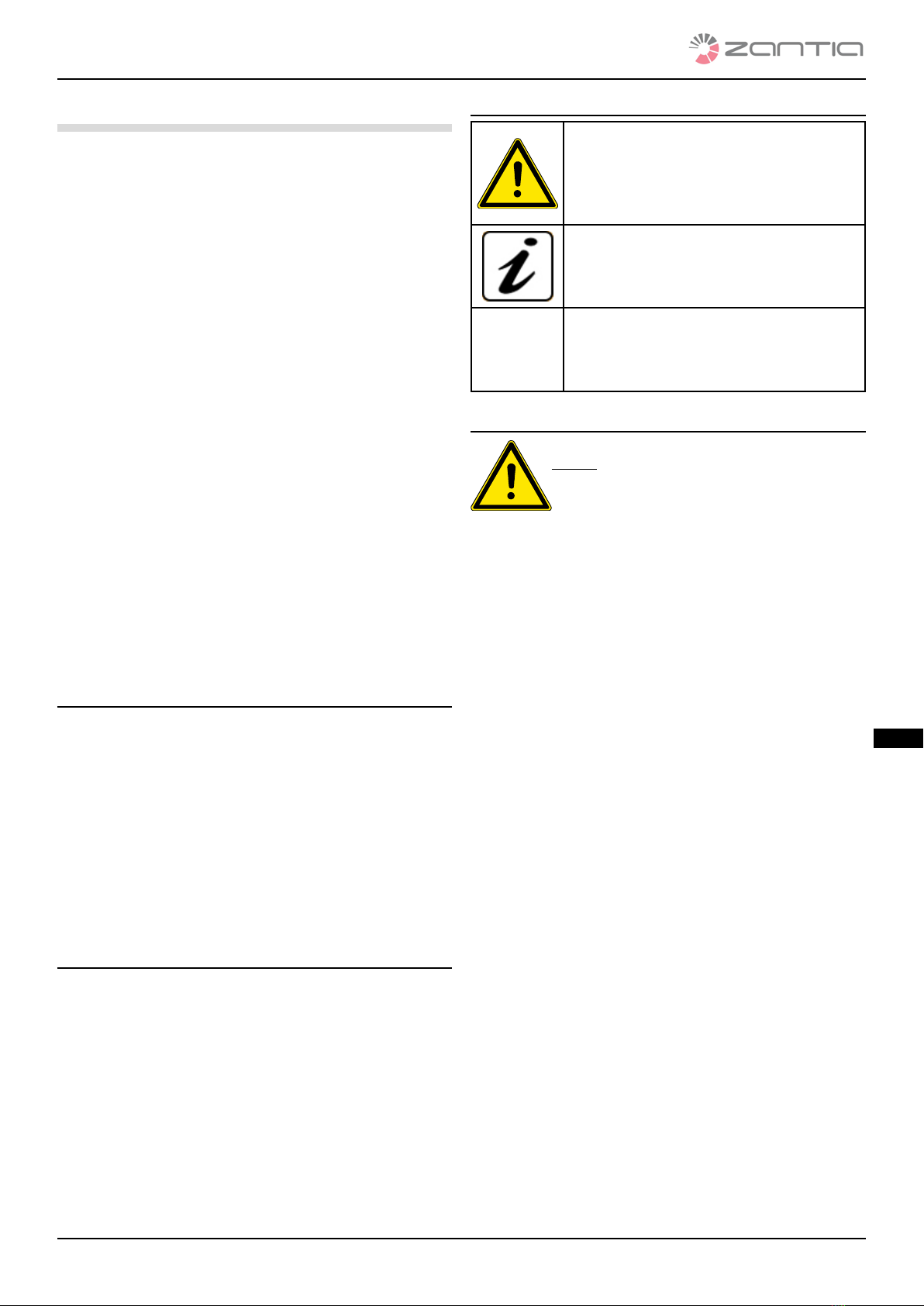
•Do not remove the feet for setting the product body on
the oor to guarantee proper insulation, especially for
oors made of ammable materials.
•Place a oor protection plate as a base for the product if
the oor is made of ammable material, such as parquet
or carpets. (considering that the plate must extend be-
yond the front of the stove by at least 25/30cm).
• It is strictly forbidden to use flammable liquids to light
the fi e; the pellets light automatically when the stove
is on.
•Extraordinary maintenance operations must only be car-
ried out by authorised and qualied personnel.
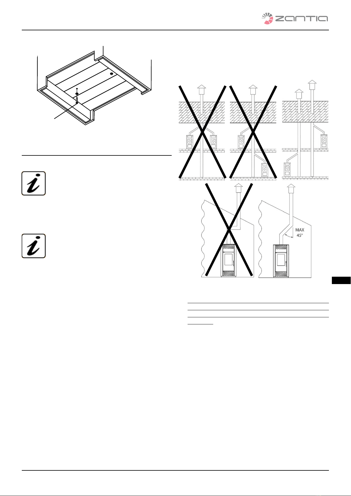
•For seasonal use of the stove, in case of improper draught
or adverse weather conditions (temperatures < 0°C), make
sure that the uid is perfectly insulated and not obstruct-
ed to avoid freezing or the backow of ue gas.
•If the ue catches re, immediately switch o the product,
unplug it and never open the door. Then call the compe-
tent authorities.
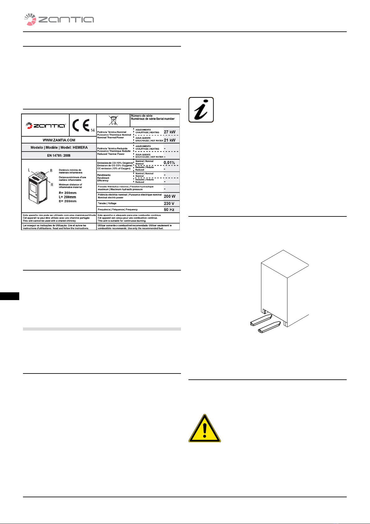
•As the product has an air consumption necessary for com-
bustion, it is recommended to connect the product to the
outside by means of suitable piping reaching the specic
inlet at the back of the stove.
•For safety purposes, it is recommended to maintain at least
20 cm between the hot sides of the stove and any amma-
ble cover materials (e.g. matchboarding walls, wallpaper
etc.) or to use specic insulating materials available on the
market. This assessment must also be made regarding fur-
niture, armchairs, curtains and similar objects.
•To facilitate technical support interventions, do not recess
the product in tight spaces, do not push it against the wall
as this could jeopardize correct ventilation.
• The absence of draught by the flue (or e.g. the obstruc-
tion or closing of brazier air inlet or of the brazier it-
self) alters functioning of the stove which, during the
automatic ignition phase, could cause too many pel-
lets to be dispensed into the brazier due to delayed
sparking of the fi e. Too much smoke in the combus-
tion chamber could cause the flue gas to light with a
sudden blaze. In this condition never open the door of
the combustion chamber.
•The pellets feeding the product must have the characteris-
tics described in this manual.
•Do not leave children alone near the stove while it is lit, as
all the hot parts could cause serious burns.
•Do not carry out any operation on the stove other than
those indicated for its regular use or those recommended
in this manual to solve simple problems. Always unplug
the appliance before intervening and only operate with
the stove cold.
•IT IS absolutely prohibited to remove the pellet tank pro-
tective grid.
•Always check and make sure that the door of the combus-
tion chamber is hermetically closed during ignition and
operation of the stove.
•Automatic ignition of the pellets is the most delicate
phase. It is recommended to always keep the product and
brazier clean so that it can be done without any problems.
•In the presence of operating faults, the product can only
be switched back on after having solved the cause of the
problem.
•Zantia is not liable for inconvenience, tampering
with, damage, or whatsoever due to failure to comply with
the provisions provided in this manual.
•This booklet is an integral part of the appliance; therefore,
it must be stored and accompany the device in case of
transfer of property.
•This appliance is not intended for use by persons (includ-
ing children) with reduced physical, sensory or mental
capabilities, or lack of experience and knowledge, unless
they have been given supervision or instruction concern-
ing use of the appliance by a person responsible for their
safety.
•Only use the fuel recommended by the manufacturer. The
product cannot be used as an incinerator. It is strictly
forbidden to use liquid fuels.
•To correctly use the product and the electronic equipment
connected to it and to prevent accidents, always observe
the indications provided in this manual.
•Before starting any operation, the user or whoever is op-
erating the product must have fully read and understood
this installation and use manual. Errors or improper set-
tings can cause dangerous conditions and/or irregular
operation.
•Switch the product o in case of failures or malfunction-
ing.
• The buildup of unburned pellets in the burner after
each "failed ignition and alarm" must be removed be-
fore attempting another ignition. Check that the burn-
er is clean and well positioned before switching it back
on.
•Do not wash the product with water. Water could inltrate
into the unit and damage the electric insulations, causing
electrical shocks.
•Install the product in rooms which are not re hazards and
are set up with all services such as supplies (air and elec-
tric) and ue gas exhausts.
•Do not stand on the product or use it as a support struc-
ture.
•Do not dry sheets on the product. Drying racks or similar
products must be kept a safety distance from the product.
There is the risk of fi e!
• All responsibility for the improper use of the product is
fully borne by the user and releases the manufacturer
from all civil and criminal liability.
•In case of failure to the ignition system, do not force igni-
tion by using ammable materials.
1.5 WARRANTY TERMS AND CONDITIONS
1. The Manufacturing Company guarantees the structure
and materials making up the product for a period of 24
months from the date of purchase, as long as the pur-
chaser sends the attached sheet within 8 days of the
date of delivery, completely lled out and keeps a copy

7
Mod. CINEA CANALIZÁVEL rev 00
Introduction
translated from the original text
IT IT
FR FR
ES ES
EN EN
as a proof of purchase. This warranty is valid as long as:
a) The purchaser has installed the product in compliance
with standards in force,
b) uses the product appropriately and
c) immediately reports any manufacturing defects.
2. Pieces subject to wear are excluded from the warranty,
namely: HIGH TEMPERATURE RESISTANT CERAMIC GLASS,
FIBREGLASS GASKETS, HANDLES, KNOBS, SILICON PAINT,
CERAMIC COVERING, IGNITION RESISTANCE, FUSES, GRIDS,
GASKETS AND INNER PARTS OF THE COMBUSTION CHAM-
BER.
3. The warranty does not cover damage caused by:
a) Incorrect installation or improper use of the product
and of its components;
b) Water and liquids dripped or poured accidentally on
the electrical and electronic components;
c) lightning and power surges;
d) excessive overheating of product or use of unsuitable
fuel;
e) deterioration from physical or chemical agents;
f) transport or tampering by unauthorised personnel.
4. The Manufacturing Company will not be held liable for
failures to electric parts due to incorrect electric connec-
tion or those where it is not possible to ascertain the prop-
er operation of the home system and the earthing system
at the time of the failure.
5. The warranty consists in supplying or replacing faulty
parts or those considered such by our Technical Depart-
ment free of charge. The replaced parts remain covered by
warranty for the remaining warranty period again starting
from the date of purchase.
6. The warranties of the manufacturers are transferred for
equipment or parts of them assembled but produced by
other companies.
7. No compensation is acknowledged for the time of ine-
ciency of the product awaiting repair.
8. The warranty is personal and cannot be transferred to
third parties.
9. If defects or breakage are detected during the period cov-
ered by the warranty, the purchaser must contact the dealer
where he bought the appliance who will check the presence
of the defect. If the defect is conrmed by the Manufacturing
Company, the spare part will be provided to the customer
free of charge at our site. To facilitate replacement opera-
tions, please provide the following information:
a) name and address of dealer;
b) date of purchase;
c) name, address and telephone number of purchaser;
d) name, address and telephone number of installer;
e) date of installation;
f) series and model of the product.
10. All shipping fees are borne by the purchasing customer,
such as the minimum charge, labour costs, transfer ex-
penses and distance fees between the site and the cus-
tomer's home.
11. We reiterate that the Manufacturing Company only pro-
vides the warranty at the above-mentioned conditions
and is in no way liable to direct or indirect damage result-
ing from the product to object or third parties.
1.5.1 WARNINGS NOTES FOR THE CUSTOMER
The appliance can be commissioned by S.T.A. (Servizio Tecni-
co Autorizzato [Authorised Technical Service]) or by a quali-
ed dealer; the Warranty is valid from the date of the receipt.
THE FOLLOWING INTERVENTIONS ARE NOT COVERED BY
WARRANTY:
Cleaning braziers - ash pan - stove; calibration interventions
(combustion - temperature - operating times, etc.); routine
maintenance interventions; interventions due to lack of and/
or loading fuel and adaptation of new combustion parame-
ters; interventions due to operating defects attributable to
lack of and/or incorrect maintenance; interventions for repair/
replacement of electric components damaged by overvoltage
or electric loads.
1.6 ORDERING SPARE PARTS
Only technical personnel authorised by Zantia must carry
out any type of intervention. Contact the authorised as-
sistance centre or your dealer to request spare parts.
Only use original spare parts.
Do not wait for components to be worn by use before replacing
them; periodical maintenance checks should be performed. The
company will not be held liable should the product and any other
accessory be used improperly or modied without authorisation.
1.7 WASTE DISPOSAL
Do not dispose of the electrical equipment with
domestic waste. Pursuant to the European Direc-
tive 2002/96/EC and subsequent amendment
2003/108/EC }on disposing of electrical and elec-
tronic equipment and its implementation in com-
pliance with national standards, exhausted electri-
cal devices must be collected separately in order to be re-used in
an eco-compatible way. The product can be delivered to specic
separate collection facilities set up by city administration or to
dealers who supply this service.
1.8 ALLOWED AND FORBIDDEN USE
• The product is intended exclusively for heating rooms.
•The product only works with wooden pellets and must be
installed inside the rooms.
•Do not use the appliance as an incinerator or in any way
other than that for which it was designed.
• Do not use any other fuel than pellets.
• Do not use liquid fuels.
• Do not use the product as a ladder or support structure.
•Do not dry sheets on the product. Any drying racks or
similar products must be kept a proper distance from the
product. Fire hazard.
• The product is not a cooking appliance.
•During cleaning operations, NEVER remove the pro-
tective grid in the pellet loading area.
All responsibility for the improper use of the prod-
uct is fully borne by the user and releases the manu-
facturer from all civil and criminal liability.
•Do not perform any unauthorised change to the appli-
ance.

8
Mod. CINEA CANALIZÁVEL rev 00
Installation
translated from the original text
IT IT
FR FR
ES ES
NL NL
EN EN
1.9 FUEL TO BE USED
The product works exclusively with pellets, cylindrical shaped
fuel obtained by mixing various types of wood pursuant to
standard DIN 51731. Therefore pellets with features dierent
than those foreseen by the standard downgrade the ecien-
cy of the appliance, causing bad combustion and the forma-
tion of encrustations.
1.10 IDENTIFICATION PLATE
g. 1 identication plate
The identication plate is applied on the back of the product.
1.11 SUPPLIED ACCESSORIES
The product is supplied together with:
• Remote control (optional);
• Power cables;
• Adjustable feet;
• Instruction booklet.
2 INSTALLATION
The indications contained in this chapter refer expressly to the
Italian installation standard UNI 10683. In any case, always re-
spect the standards in force in the country of installation.
2.1 INITIAL RECOMMENDATIONS
The installation position must be chosen depending on the
room, exhaust and ue. Check with local ocials whether there
are more restrictive prescriptions regarding fuel air intake and
ue gas exhaust system including ue and chimney. The manu-
facturing company will not be held liable in case of installation
nonconforming to laws in force, of an incorrect air exchange in
the rooms, of an electric connection nonconforming to stand-
ards and of inappropriate use of the appliance. Installation must
be carried out by a qualied technician who must issue the pur-
chaser with a declaration of conformity of the plant and take
on full responsibility for the nal installation and consequent
correct operation of the product. He must especially make sure
that:
•There is an appropriate combustion air intake and a ue
gas exhaust compliant to the type of product installed;
•Other stoves or installed devices do not put the room
where the product is installed in negative pressure (only
airtight appliances are allowed a maximum of 15 Pa of
negative environmental pressure);
•There is no ue gas backow into the room with the prod-
uct lit;
•Flue gas exhaust is implemented in full safety (dimension-
ing, ue gas sealing, distance from ammable materials).
It is especially recommended to check the data on the
ue identication plate for the safety distances which
must be respected in the presence of combustible ma-
terials and the type of insulation material to be used.
These prescriptions must always be strictly respected
to avoid serious damage to personal health and to the integrity
of the home. Installation must guarantee easy access in order to
clean the device, the exhaust gas pipes and the ue. Installation
in single room apartments, bedrooms and baths is only allowed
for airtight or closed appliances provided with appropriate com-
bustion air ducting directly outside. Always maintain an appro-
priate distance and protection to keep the product from coming
into contact with water. Should several appliances be installed,
the outside air intake must be dimensioned accordingly.
2.2 HANDLING AND TRANSPORT
Make sure that the lifting and transport devices used bear the
weight of the stove indicated in chap.8 "Technical data". Lift
the stove using a forklift truck, whose forks must be inserted
inside the specic seats of the wooden crate.
g. 2 lifting package
Place the product on the oor with caution, avoiding
any impact in order to position it in the room.
2.3 PACKAGE OPENING PROCEDURE
Remove all the parts making up the package (polystyrene,
wood, plastic). All the packaging materials can be reused for
similar use or disposed of as urban waste in compliance with
standards in force.
After having removed the packaging, make
sure that the product is intact.
Handle the appliance with suitable means
paying attention to the relevant safety stand-
ards in force. Do not tip the package over.
To open the package, proceed as follows:
• Remove the fasteners (g.3) to the pallet;
•Unscrew the xing screws (g.3 ref. A) of the stove base
located underneath the pallet;
•Handle the product by hand, placing it near the installa-
Example

9
Mod. CINEA CANALIZÁVEL rev 00
Installation
translated from the original text
IT IT
FR FR
ES ES
NL NL
EN EN
tion site
g. 3 xing removal
2.4 FLUE GAS GAS EXHAUST INSTALLATION
2.4.1 PREAMBLE
The indications contained in this chapter refer ex-
pressly to the European standards EN13384 - EN1443
- EN1856 - EN1457.
IMPORTANT!! Have a qualified installer check the effici -
cy and condition of the flu , compliance with national and
local standards for flue gas ducts and the use of appropri-
ate materials.
The information above is purely indicative for
correct installation. Zantia is not liable for installa-
tion.
2.4.2 FLUE
Every appliance must have a vertical duct called ue to release
combustion exhaust outside the home via natural draught.
The ue must meet the following requirements:
•It must not be connected to any other replace, stove,
boiler or range hood of any kind.
•It must be kept at safe distance from combustible or am-
mable materials by means of air gap or suitable insulation.
•Its internal cross-section must be even, possibly circular:
square or rectangular cross-sections must have rounded
edges with a radius not below 20mm; maximum side ratio:
1.5; walls as smooth as possible and without any narrow-
ing; curves must be even and without discontinuity, axis
deviation must not exceed 45°.
•Every appliance must have a ue with a 80 mm diameter
and whose height must not be below that declared (see
table 1),
•Never use two stoves, a stove and a replace or a stove and
a wood burning stove in the same room, since the draught
of one appliance can damage the draught of the other.
Moreover, collective ventilation ducts are not allowed,
since they can create negative pressure in the place of in-
stallation, even when installed in adjacent or communicat-
ing rooms.
•IT is prohibited to create xed or moving openings on the
ue to connect appliances other than the one it is serving,
•IT is prohibited to pass other air adduction ducts or tubes
through the ue, even if it is oversized.
A
•IT is advisable that the ue is tted with a solid material
and condensate collection chamber, located under the in-
let, in order for it to be easily opened and inspected from
the airtight door.
•When using ues with parallel outlets, it is recommended
to rise the bracing pipe by one element. (g. 4).
g. 4 allowed and forbidden ue gas exhaust installation meth-
ods
•For the installation of products with top flue gas ex-
haust, it is mandatory to use the flue gas kit requiring
installation of the upright pipe which remains inside
the stove.
2.4.3 CHIMNEY
The top of the ue must be provided with a device, called
chimney, which facilitates releasing combustion products
into the atmosphere. The chimney must meet the following
requirements:
•Have an internal cross-section and shape equivalent to
that of the ue.
•The outlet cross-section must be at least twice the
cross-sectional area of the ue.
•The chimney which exits the roof or which remains in con-
tact with the outside (for example for an open slab) must
be covered with bricks and anyway well insulated. Be built
in a way to prevent penetration of rain, snow, and foreign
bodies into the ue and so that in the presence of wind in
any direction and inclination, discharge of the combustion
products is still assured (wind barrier chimney).
•The chimney must be positioned in such a way as to en-
sure proper dispersion and dilution of combustion prod-

10
Mod. CINEA CANALIZÁVEL rev 00
Installation
translated from the original text
IT IT
FR FR
ES ES
NL NL
EN EN
ucts outside the backow area.This area has dierent sizes
and shapes depending on the inclination angle of the roof,
making it necessary to use the minimum heights provided
in g. 5.
•The chimney must be windproof and be higher than the
ridge (see g.5).
•The chimney must be positioned away from buildings or
other obstacles that are higher than the chimney itself
(see g.5).
g. 5 allowed and forbidden chimney installation methods
Roof slope [G]
Horizontal
width of the
backfl w area
from the ridge
axis A[m]
Minimum
height of roof
outlet Hmin =
Z+0.50m
Height of the
backfl w area
Z [m]
15 1.85 1.00 0.50
30 1.50 1.30 0.80
45 1.30 2.00 1.50
60 1.20 2.60 2.10
tab.1
2.4.4 INSTALLING A COMBUSTION AIR INTAKE
Every solution described allows for the following alternatives:
•Outside air drawn through a duct (inner Ø: 50mm; max
length 1.5 m) connected to the air intake located on the
rear of the boiler.
•Air drawn directly from the room of installation, provided
that there is an air intake of at least 100 cm² on the wall
communicating with the exterior
In both cases, it is important to periodically verify that air pas-
sage is not obstructed.
at roof
sloped roof
IMPORTANT: This appliance cannot be used in the
event of shared flue .
2.5 POSITIONING
2.5.1 GENERAL NOTES
IT is prohibited to install the stove in bed-
rooms, bathrooms, in rooms with showers and
in rooms with another heating appliance with-
out appropriate ventilation (fi eplace, stove,
etc.), outdoors exposed to weather agents or in
moist areas.
The stove must be installed in a place that allows for safe and
easy use and simple maintenance. That place must be provid-
ed with an electric system earthed as required by standards in
force.
ATTENTION: make sure that the electric connec-
tion plug is accessible even after installation of
the stove.
2.5.2 MINIMUM SAFETY CLEARANCES
We recommend positioning the product as much as possible
in the centre of the room to be heated to facilitate even distri-
bution of heat and to provide ideal performance.
Place a oor protective plate near a ue or ammable
material (e.g. parquet or carpet).
FOR safety purposes, it is recommended to maintain at least
20 cm (A) and (B) between the hot sides of the stove and any
ammable cover materials (e.g. matchboarding walls, wallpa-
per etc.) or to use specic insulating materials available on the
market.
Installation in a corner
Flue
.
Through
pipe insula-
tion
Walls

11
Mod. CINEA CANALIZÁVEL rev 00
Installation
translated from the original text
IT IT
FR FR
ES ES
NL NL
EN EN
Wall installation
Heat radiation area
Hot air safety area
Flammable object
HOT
ZONE
Distance from flammable or false eilings
Distance of the exhaust system from flammable pa ts
g. 6 minimum safety clearances for positioning product
2.5.3 FLOOR PROTECTION
In the event of heat sensitive or ammable ooring, this must
be protected (e.g., by means of steel sheets, marble slabs or
tiles). Whatever protection you choose, this must protrude at
least 300 mm at the front and 150 mm from the sides of the
stove and must withstand its weight and have a thickness of
at least 2 mm (see following g.).
Flammable object
Protection

12
Mod. CINEA CANALIZÁVEL rev 00
Installation
translated from the original text
IT IT
FR FR
ES ES
NL NL
EN EN
g. 7 oor protections
2.5.4 MINIMUM CLEARANCE FOR POSITIONING
THE AIR INTAKE
The combustion air intake of the pellet stove cannot be con-
nected to an air distribution system or to a wall air intake. The
described measures and requirements must be complied
with to ensure its correct and safe positioning. These distanc-
es must be observed to prevent taking combustion air from
another source; for example, opening a window can suck out
the outside air, depriving the stove of it.
The air intake must be located at least at:
1.5 m beneath Doors, windows, ue
gas exhausts, gaps,
etc.
1.5 m Horizontally away
0.3 m Above
1.5 m Away from Flue gas outlet
tab.2 min. clearances air intake positioning
Protection
min. 2 mm
Floor
Air intake with
non-lockable
grille
2.5.5 FLUE GAS EXHAUST DUCT
The pipes must ALWAYS be installed according to the
standards and instructions of the manufacturer and any-
way with the silicon gasket supplied to guarantee its seal-
ing.
•IT is prohibited to install dampers or other valves that can
obstruct the ue gas exhaust.
•IT is prohibited to install one ue in which ue gas or
vapours of other appliances (boilers, hoods, etc.) are ex-
hausted.
2.5.6 PIPES AND MAXIMUM USABLE LENGTHS
Pipes made of painted aluminised steel (minimum thickness
1.5 mm), stainless steel (Aisi 316) with a 100 mm diameter (for
pipes inside the ue max. 150 mm). Hoses (made of stainless
steel with smooth internal wall) can be used if they fall within
the limits set forth by law; the male-female coupling collars
must have a minimum length of 50 mm. The diameter of the
pipes depends on the type of system.
TYPE OF SYSTEM WITH Ø 100 mm DOU-
BLE WALLED PIPE
Minimum length 2m
Maximum length (with 3 90° elbows) 8m
For installations located at over 1200 m asl mandatory
Maximum number of elbows 4
Horizontal segments with min slope 5% 2m
tab.3 max. pipe length
NOTE: pressure drops of a 90° elbow can be com-
pared to those of 1 metre pipe; the inspectable tee
fitting must e considered as a 90° elbow.
Tee tting
Fitting

13
Mod. CINEA CANALIZÁVEL rev 00
Installation
translated from the original text
IT IT
FR FR
ES ES
NL NL
EN EN
g. 8 pipe length
2.5.7 BORES FOR PASSAGE OF EXHAUST PIPE
ON WALL OR ROOF: RECOMMENDED IN
STALLATION AND DIAMETER
Once the position of the stove has been established (par.
2.5.6), a hole must be drilled for passage of the ue gas ex-
haust pipe. This varies according to the type of installation
(and of the exhaust pipe diameter) and on the type of wall or
roof. The insulation material must have mineral origin (rock-
wool, ceramic bre) with a nominal density exceeding 80 kg/
m3.
Insulation thickness
[mm]
Diameter of the
holes [mm]
Wooden wall, or
anyway flammable or
with flammable pa ts
100 300
Cement wall or roof 50 200
Brick wall or roof 30 160
tab.4 bore diameter for exhaust pipe passage
2.5.8 USING A TRADITIONAL FLUE
If you wish to use an existing ue, we recommend having
it checked by a professional chimney sweep to ensure that
it is fully airtight. This is because the ue gas, being slightly
pressurised, can inltrate into possible cracks in the ue and
invade the living areas. Should the ue not result in perfect
conditions after the inspection, it is advisable to have it sealed
with new materials. In the event of a large-size existing ue,
we recommend inserting a pipe having a diameter of maxi-
mum 150 mm; it is also advisable to insulate the ue gas ex-
haust pipe. The following gures describe the solutions to be
chosen in the event an existing ue is used
Insulation
Tee tting
Tee tting
Airtight cap
Tee tting
Cleaning
direction
Cleaning
direction
Cleaning direction
.
g. 9 traditional ue
2.5.9 USING AN EXTERNAL FLUE GAS DUCT
AN external ue gas duct can be used only if it meets the fol-
lowing requirements:
• Only insulated (double-walled) stainless steel pipes must
be used fastened to the building (following g.).
• An inspection must be provided at the base of the duct
to carry out periodic verications and maintenance oper-
ations.
• It must have a wind barrier chimney and respect the "d" dis-
tance from the ridge of the building as shown in par. 2.4.3, tab.
1.
• The following gure shows the solution to be chosen in the
event an external fuel gas duct is used.
Chimney
Insulation
Inspection
doors
Max Ø 150
Tee tting
Inspection
Air intake with non-lockable grille

14
Mod. CINEA CANALIZÁVEL rev 00
IT IT
FR FR
ES ES
NL NL
EN EN
First ignition
translated from the original text
IT IT
FR FR
ES ES
NL NL
EN EN
g. 10 external ue
2.5.10 INSTALLING A COMBUSTION AIR INTAKE
Every solution described allows for the following alternatives:
•Outside air drawn through a duct (inner Ø: 50mm; max.
length 1.5 m) connected to the air intake located on the
rear of the stove.
•Air drawn directly from the room of installation, provided
that there is an air intake near the stove of at least 100 cm²
on the wall communicating with the exterior
In both cases, it is important to periodically verify that air pas-
sage is not obstructed.
IMPORTANT: This appliance cannot be used in
the event of shared flue .
2.6 ELECTRICAL CONNECTION
Ensure that the electrical system and sockets can withstand
the maximum power consumption of the product, shown on
the identication plate.
•Ensure that the system is earthed and
equipped with a residual current device, in
compliance with the standards in force
•The stove must be connected to a standard electric sock-
et, 230v – 50Hz voltage, without using adapters, multiple
sockets or extension cables.
•Ensure that the mains connection cable is not in contact
with the hot parts of the stove and that it is not crushed
by it.
•The stove system is protected by a fuse inserted in the
master switch at the rear of the product.
Always remember to unplug the product before perform-
ing any maintenance and/or checks and whenever a long
idle period is foreseen.
Closing ange
Stainless steel or
aluminium airtight
closing ange
External air intake
with non-lockable
grille
Inspection
g. 11 electric connection of the stove
Once the power cable at the back of the stove is plugged in,
move the switch, also located at the back, to (I) therefore:
•The switch at the back of the stove is for powering the sys-
tem.
•There is a fuse box at the back of the stove near the power
socket. Open the lid of the fuse box with a screwdriver and
have an authorised technician change any fuses if neces-
sary (3.15 A delayed).
g. 12 electric power supply
3 FIRST IGNITION
Before commissioning the product, it is manda-
tory to have specialised personnel perform the
“FIRST IGNITION” and calibration. To this end,
we recommend contacting the authorised
Zantia technical assistance centre. The
companyshall not be held liable for malfunctions caused by improper
installation, failed or improper rst ignition or misuse. Before
switching the product on, always check that the brazier
is pushed to the back of the rear wall of the combustion
chamber. When the tank is loaded the rst time, the auger
must ll up for a certain amount of time during which the pel-
lets are not dispensed into the brazier.
3.1 PELLET LOADING PROCEDURE
•Fuel is loaded by opening the door at the top of the stove.
•Pour the pellets slowly until they deposit at the bottom of
the tank.
Never remove the protective grid inside the
tank. Do not allow the pellet bag to come into
contact with hot surfaces while loading.
Do not insert any other type of fuel in the tank
except pellets compliant with the specifi ations shown
previously.
Store spare fuel a safety distance away from the stove.
Do not pour pellets directly into the brazier, but only into the tank.
Socket Stove switch
Fuse box

15
Mod. CINEA CANALIZÁVEL rev 00
Instructions for use
translated from the original text
IT IT
FR FR
ES ES
NL NL
EN EN
IT IT
FR FR
ES ES
NL NL
EN EN
Many of the stove surfaces are very hot (door, handle,
glass, flue gas outlet pipes, tank door, etc.). It is therefore
recommended to avoid coming into contact with these
parts without suitable protective clothing.
g. 13 pellet loading
3.2 WARNINGS
Comply with all national and European stand-
ards when installing the appliance. Do not use
the appliance as an incinerator or in any way
other than that for which it was designed.
• Do not use any other fuel than pellets.
• Do not use liquid fuels.
•When the appliance is running, it reaches high tempera-
tures, especially the external surfaces; handle with care to
avoid burns.
•Remove the product from the brazier and all components
from the glass which could burn (instruction manual, vari-
ous stickers and any polystyrene). Check that the brazier is
positioned correctly and rests properly on its base.
First ignition could fail as the auger is empty and
is not always able to fill the brazier with the neces-
sary amount of pellets on time for a regular start.
Cancel the failed ignition alarm by keeping the ON/OFF
key pressed for a few seconds. Remove the pellets left in
the brazier and repeat ignition. (see par. “Troubleshoot-
ing”).
•If after several ignition attempts the ame has not yet ap-
peared despite a regular pellet supply, check that the bra-
zier is housed properly. It must fitperfectly in its seat and
be clear of any ash buildup. If this check nds nothing
abnormal, it means there could be a problem linked to the
product components or attributable to incorrect installa-
tion.
In this case, REMOVE THE PELLETS FROM THE
BRAZIER AND REQUEST THE INTERVENTION
OF AN AUTHORISED TECHNICIAN.
Do not touch the stove during the first ignition
as the paint hardens in this phase.
IT is good practice to guarantee effici t ven-
tilation of the environment during the first ig-
nition as the product issues some smoke and
the smell of paint.
•Do not remain near the stove and, as said above, ventilate
the environment. The smoke and smell of paint will dis-
appear after about an hour of operation. Remember that
Pellet loading
they are not harmful to health.
•The stove is subject to expansion and contraction during
ignition and cooling phases and therefore you could hear
some slight creeks.
•This is absolutely normal as the structure is built in lami-
nated steel and must not be considered a defect.
•IT is extremely important to make sure not to overheat the
product immediately, but to bring it to operating temper-
ature gradually by initially using low-power outputs.
•This will prevent from damaging the ceramic tiles, welds
and steel structure.
DO NOT LOOK FOR HEATING PERFORMANCE IM-
MEDIATELY!!!
•Do not perform any unauthorised change to the appli-
ance.
•Use only the original spare parts recommended by the
manufacturer.
4 INSTRUCTIONS FOR
USE
4.1 PREAMBLE
The product unites the heat of the re with the
convenience of automatic temperature manage-
ment, ignition and switch o, with the possibili-
ty of programming it for several days. Automatic
loading and the large capacity of the tank provide
greater autonomy and enhanced management of the pellet
stove. . The product must always operate with the door abso-
lutely closed. IT IS essential for the exhaust system to be air-
tight. The product must always be clean to guarantee ecient
performance and correct operation.
4.2 CONTROL PANEL
The control panel displays information regarding the operat-
ing status of the product. Accessing the menu, you can obtain
various types of display and perform the settings available de-
pending on the access level. The displayed information has
dierent meanings, according to the operating mode and its
position. Figure I4 shows an example of the product o or on.
g. 14 control panel o

16
Mod. CINEA CANALIZÁVEL rev 00
Instructions for use
translated from the original text
IT IT
FR FR
ES ES
NL NL
EN EN
4.2.1 DESCRIPTION OF BUTTONS
1 6
clock room temp
2 5
status dialogue power 4
3
Status
Chrono
Glow plug
Auger
Flue gas ex-
tractor
Heat exchanger
Not used
Alarm
g. 14a Description of buttons
But-
ton Description Mode Action
1Increase tem-
perature
PROGRAMMING Changes/increases the value of the se-
lected menu
OPERATING/OFF Decreases the value of the water/room
temperature thermostat
2Decrease
temperature
PROGRAMMING Changes/decreases the value of the
selected menu
OPERATING/OFF Decreases the value of the water/room
temperature thermostat
3Menu
- Accesses the MENU
MENU Accesses the next submenu level
PROGRAMMING Sets the value and proceeds to the
next item of the menu
4ON/OFF -
unlock
OPERATING Held down for 2 seconds, turns the
stove on or o.
LOCK Unlocks the stove and brings it back
to o
MENU/PROGRAM-
MING
Accesses the higher menu level; modi-
cations are stored in the memory
5Decrease
power
OPERATING/OFF Changes the power yielded by the
product
MENU Proceeds to the next item of the menu
PROGRAMMING
Proceeds to the next item of the sub-
menu; modications are stored in the
memory
6Increase
power
OPERATING/OFF Changes the heat exchanger speed
MENU Proceeds to the previous item of the
menu
PROGRAMMING
Returns to the previous item of the
submenu; modications are stored in
the memory
tab.5 description of buttons

17
Mod. CINEA CANALIZÁVEL rev 00
Instructions for use
translated from the original text
IT IT
FR FR
ES ES
NL NL
EN EN
4.2.2 REMOTE CONTROL
The product is mainly commanded from the control panel at
the top. It is however possible to purchase the remote control
as an accessory to perform the following functions:
Ref. Description
1
Switch the stove on and o:
Point the remote control and simultaneously press the top keys
marked“+”.
2Change power of the fi e:
Press the“+” and“-“ keys marked with the re symbol.
3Adjust room temperature:
Press the“+” and“-“ keys marked with the thermometer symbol.
The remote control is the infrared type and therefore the sig-
nal cannot bypass walls or other solid objects but it can ex-
ploit the reection of waves on walls in the room.
Replacing batteries
The batteries are housed at the bottom of the remote control.
To replace them, remove the battery holder, remove or insert
the battery by following the symbol on the remote control
and on the battery itself.
A235 12V batteries not included.
The batteries used contain metals harmful for
the environment and must therefore be dis-
posed of separately in specific ontainers.
If the remote control is off because the bat-
tery is missing, the product can be command-
ed from the control panel at the top. When re-
placing batteries, pay attention to the polarity
by following the symbol on the internal com-
partment of the remote control.
1
2
3
4.3 USER MENU
The following is a synthetic description of the structure of the
user manual. The various items can be accessed by scrolling
the keys (5-6) tab. 5. To enter the menu, press the key (3) tab.
5.
01 - Adjust fans
02 - Set clock
01 - day (day of the week)
02 - hours (time of the day)
03 - minutes
04 - day (day of the month)
05 - month
06 - year
03 - Set chrono
01 - enable chrono
01 - enable chrono (on/o)
02 - program day
01 - day chrono (on/o)
02 - start 1 day (time)
03 - stop 1 day (time)
04 - start 2 day (time)
05 - stop 2 day (time)
03 - program week
01 - week chrono (on/o)
02 - start prog 1 (time)
03 - stop prog 1 (time)
04 - Monday prog 1 (on/o)
- - -
10 - Sunday prog 1 (on/o)
- - - continue with prog 2 and prog 3
04 - program weekend
01 - weekend chrono
02 - start 1
03 - stop 1
04 - start 2
05 - stop 2
04 - Choose language
01 - Italian
02 - French
03 - English
04 - German
05- Standby mode (on/o)
06 - Buzzer (on/o)
07 - Initial load (on/o)
08 - Stove status
4.4 ADJUSTING FANS
This allows you to adjust the two supplementary fans inde-
pendently. The selections in tab.6 below can be made for each
of the two fans. From the 01 - Adjust fans menu, accessed

18
Mod. CINEA CANALIZÁVEL rev 00
Instructions for use
translated from the original text
IT IT
FR FR
ES ES
NL NL
EN EN
by pressing the key (4) g. 14a, the display shown in g. 15
appears. Act on the keys (1) (fan 2) and 2 (fan 3) to make the
selections.
set fan 2 fan 3
Acorresponding to power select-
ed
corresponding to power select-
ed
0fan deactivated fan deactivated
1Speed = P1 Speed P1
2Speed = P2 Speed = P2
3Speed = P3 Speed = P3
4Speed = P4 Speed = P4
5Speed = P5 Speed = P5
tab. 6 fan adjustment
g. 15 control panel - fan adjustment
4.5 SETTING THE CLOCK
This allows you to set the current time and date. The control
panel is equipped with a lithium battery that allows for 3/5-
year autonomous operation of the internal clock. To modify
the values, from the 03 - Set Chrono menu, using the (5) and
(6) keys g. 14a scroll the items until “02 - program day”,
choose the new values with the keys (1) and (2) g. 14a, and
conrm by pressing key (3) g. 14a.
g. 16 control panel - time and date setting
4.6 SETTING CHRONOTHERMOSTAT
Allows you to enable and disable all the chronothermostat
functions.
g. 17 control panel - enabling chronothermostat functions
4.6.1 DAILY PROGRAMMING
To enable/disable and set the daily chronothermostat func-
tions.
g. 18 control panel - daily programming
You can set two operating time slots according to tab. 7,
where the OFF setting tells the clock to ignore the command:
Selection Description Possible values
START 1 activation time time - OFF
STOP 1 deactivation time time - OFF
START 2 activation time time - OFF
STOP 2 deactivation time time - OFF
tab. 7 operating time slots setting
4.6.2 WEEKLY PROGRAMMING
To enable/disable and set the weekly chronothermostat func-
tions. Access via the menu: Set chrono -> weekly program ->
See item chap. 4.3
g. 19 control panel - weekly programming
The weekly programmer is provided with 4 independent pro-
grams, whose nal eect is the combination of the 4 single
programs. The weekly programmer can be activated or deac-
tivated. Moreover, by setting OFF in the time eld, the clock
will ignore the corresponding command.
Program with care, avoiding any activation or
deactivation time overlap in the same day in
dierent programs.
Program 1
Selection Description Settable status
START PROG 1 Activation time Time - o
STOP PROG 1 Deactivation time
MONDAY PROG 1
Reference day
On/o
TUESDAY PROG 1
WEDNESDAY PROG 1
THURSDAY PROG 1
FRIDAY PROG 1
SATURDAY PROG 1
SUNDAY PROG 1
tab. 6 fan adjustment
Another 3 weekly programming levels are avail-
able.
4.6.3 WEEKEND PROGRAMMING
To enable/disable and set weekend chronothermostat func-
tions (days 5 and 6, i.e. Saturday and Sunday).
g. 20 control panel - weekend programming

19
Mod. CINEA CANALIZÁVEL rev 00
Instructions for use
translated from the original text
IT IT
FR FR
ES ES
NL NL
EN EN
• To prevent misunderstandings and unwant-
ed start-up or switch-o, activate only one
program at a time if you are not sure of what
you want to obtain.
• Deactivate the daily program if you want to use the
weekly program.
• Always keep the weekend program deactivated when
using weekly programs 1, 2, 3 and 4.
• Activate the weekend program only upon deactivat-
ing the weekly one.
4.7 LANGUAGE SELECTION
This allows you to select the dialogue language among those
available.To modify the language, go to the menu 04 - Choose
language, using the keys (1) and (2) g. 14a to scroll the items
until you reach the desired language.
g. 21 control panel - language selection
4.8 STANDBY MODE
Activates the "STANDBY" mode which switches o the stove
after the room temperature has remained higher than the
set value beyond the default time. When the stove switches
o in this condition, it can only switch back on when the set
temperature is lower than the room temperature for a deter-
mined amount of time. To modify the mode, go to the menu
05- Standby mode, and use the keys (1) and (2) g. 14a to
activate it/deactivate it.
4.9 BUZZER MODE
When set at “OFF” the acoustic signal is disabled. To modify
the mode, go to the menu 06 - Buzzer, and use the keys (1)
and (2) g. 14a to activate it/deactivate it.
4.10 INITIAL LOAD
Perform the operation below when the pellet
loading pipe is empty.
This allows you to perform a pellet preload lasting 90” with
the stove o and cold. Start by pressing the key (1) and inter-
rupt by pressing the key (4). The following also appear on the
display: Timer (A), Power (B), Room Temp. (C).
g. 22 control panel - initial pellet loading
4.11 STOVE STATUS
Displays the instantaneous status of the stove by showing the
1
AC B
status of the various devices connected to it. Various pages
are available and displayed in sequence. The following also
appear on the display: Timer 1 (A), Time-out (B), Status (C),
Alarm delay (D), Operating status (E), Flue gas Temp. (F), Flue
gas Extraction speed (G), Heat exchangers 2 and 3 status (H),
Instantaneous power (I), Heat exchanger 2 speed (L), Heat ex-
changer 3 speed (M), Alarm in progress (N).
g. 23 control panel - stove status display
4.12 IGNITION
To switch the product on, press the key (1) for a few seconds.
The display shows when the snow has started (see g. 24)
g. 24 control panel - ignition
4.13 START-UP PHASE
The product performs the start-up phases in sequence as de-
ned by the parameters managing levels and times.
4.14 FAILED IGNITION
When a time preset by the manufacturer has elapsed and the
ue gas temperature has not reached the minimum value,
also preset by the manufacturer, the product goes into alarm
status (see table 7 problems/causes/remedies in chap. 7.3).
4.15 STANDARD OPERATION
Upon successfully completing the start-up phase, the stove
switches to the "operating" mode that represents standard op-
eration. If the ue gas temperature exceeds a value preset by
the manufacturer, the heat exchangers are enabled, g. 25.
Heat exchangers 2 and 3 are only activated if they are en-
abled.
A
B
E
D
CFGH I
LM
N
1

20
Mod. CINEA CANALIZÁVEL rev 00
IT IT
FR FR
ES ES
NL NL
EN EN
Instructions for use
translated from the original text
IT IT
FR FR
ES ES
NL NL
EN EN
g. 25 control panel - operating condition
4.16 CHANGING THE ROOM TEMPERATURE
SETTING
To change the room temperature, just act on the keys (1) and
(2). The display shows the current status of the temperature
setting, g. 26.
g. 26 control panel - room temperature modication
4.17 USING THE EXTERNAL THERMOSTAT/
CHRONOTHERMOSTAT
It is possible to connect an external thermostat to the stove
for remote management of some functions.
• external thermostat: set a temperature of 7°C.
•external chronothermostat: set temperature of 7°C and
from the menu “03 Set chrono -> 01 enable chrono” disable
the chrono function (o).
The stove is enabled when it is on and the contact
is closed. The external thermostat must be con-
nected by the Authorised Assistance Centre.
4.18 ROOM TEMPERATURE REACHES THE SET
TEMPERATURE
When the room temperature or the ue gas temperature have
reached the set value, the heat output is automatically
brought to the minimum value“MODULATION" condition, see
g. 27.
g. 27 control panel - set temperature modulation
If STANDBY mode is activated, the stove switches o with a
delay equal to the time preset by the manufacturer after hav-
ing reached the set temperature.
The stove restarts after the room temperature
drops below the set temperature for an amount
of time preset by the manufacturer.Troom < Tset.
4.19 CLEANING THE BRAZIER
During standard operating conditions, the “BRAZIER CLEAN-
ING” mode is activated at intervals established by the manu-
1
2
facturer for a preset amount of time.
g. 28 control panel - brazier cleaning mode
4.20 SWITCH-OFF
To switch the stove o, just press the button (4) for about 2
seconds.The auger stops immediately and the ue gas extrac-
tor is brought to high speed. "FINAL CLEANING" is carried out.
When the ue gas temperature has dropped to a value set by
the manufacturer, the ue gas extractor is disabled after a pre-
set amount of time.
g. 29 control panel - nal cleaning
g. 30 control panel - switch-o
4.21 RESTART
The stove cannot be restarted until the ue gas temperature
drops below the preset value for the set amount of time.
Always clean the brazier before restarting.
g. 31 control panel - cooling wait before restart
4.22 FUNCTIONS OF MECHANICAL AND
ELECTRIC COMPONENTS
Auger motor
The auger motor drives the screw
which brings pellets from the tank
to the brazier.
4
Table of contents
Languages:
Other ZANTIA Stove manuals
Popular Stove manuals by other brands

Napoleon
Napoleon GDS60-1N Installation and operation manual

Euroheat
Euroheat EVO Aqua Installation & servicing instructions

Hamlet
Hamlet Hereford Operating & installation manual

American Energy Systems
American Energy Systems Ovation OV-1700 Owner's Manual & Installation Instructions

VARDE OVNE
VARDE OVNE Farso 1 quick guide

hergom
hergom EB-1 Installation, use and maintenance instructions