ZBA Z-1070 User manual

ZBA Inc.
Page 1 of 33
Copyright © 2007. All rights reserved.
No warranty of any kind is made in regard to this material, including, but not
limited to, implied warranties of merchantability or fitness for a particular purpose.
Although every effort is made to assure accuracy and completeness, we can not
be held liable for any errors contained herein or incidental or consequential
damages in connection with furnishing, performance or use of this material.
We shall be under no liability in respect of any defect arising from fair wear and
tear, willful damage, negligence, abnormal working conditions, failure to follow
the instructions and warnings, or misuse or alteration or repair of the products

ZBA Inc.
Page 2 of 33
without written approval.
No part of this document may be reproduced, transmitted, stored in a retrieval
system, transcribed, or translated into any language or computer language in any
form or by any means electronic, mechanical, magnetic, optical, chemical,
manual or otherwise, without express written consent and authorization.
We reserve the right to make changes in product design without reservation and
without notification. The material in this guide is for information only and is
subject to change without notice.
All trademarks mentioned herein, registered or otherwise, are the properties of
their various respective owners.
Laser Safety
The portable data terminal complies with safety standard IEC 60825 for a Class I
laser product. It also complies with CDRH as applicable to a Class II laser
product. Avoid long term staring into direct laser light.
Radiant Energy: The advanced portable data terminal uses a low-power visible
laser diodes operating at 650nm in an opto-mechanical scanner resulting in less
than 3.9µW radiated power as observed through a 7mm aperture and averaged
over 10 seconds.
Do not attempt to remove the protective housing of the scanner, as un-scanned
laser light with a peak output up to 0.8mW would be accessible inside.
Laser Light Viewing: The scan window is the only aperture through which laser
light may be observed from this product. A failure of the scanner motor, while the
laser diode continues to emit a laser beam, may cause emission levels to exceed
those for safe operation. The scanner has safeguards to prevent this occurrence.
If, however, a stationary laser beam is emitted, the failing scanner should be
disconnected from its power source immediately.
Adjustments: Do not attempt any adjustments or alteration of this product. Do
not remove the protective housing of the scanner. There are no user-serviceable
parts inside.
Caution: Use of controls or adjustments or performance of procedures other
than those specified herein may result in hazardous laser light exposure.
Optical: The use of optical instruments with this product will increase the
possibility of eye hazard. Optical instruments include binoculars, magnifying
glasses, and microscopes but do not include normal eye glasses worn by the
user.

ZBA Inc.
Page 3 of 33
TABLE OF CONTENTS
1. General Information.................................................................................................... 4
1.1. Introduction.............................................................................................................. 4
1.2. Unpacking................................................................................................................ 4
Optional Accessory......................................................................................................... 5
1.3. Device Outline......................................................................................................... 6
1.4. Battery Care............................................................................................................. 6
1.5. Bluetooth® Communication.................................................................................... 7
1.5.1. Connection Mode:............................................................................................. 8
1.5.2. Bluetooth Device Address:............................................................................... 8
1.5.3. Personal Identify Number Code: ...................................................................... 8
1.5.4. Pairing PDC as SPP Master:............................................................................. 8
1.5.5. Pairing PDC as SPP Slave:............................................................................... 8
1.5.6. Connect/Disconnect with Target Devices:........................................................ 9
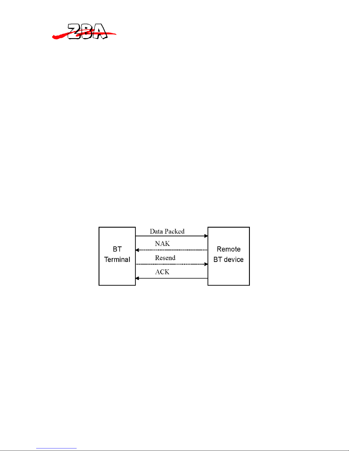
1.5.7. Reliable RF Communication: ........................................................................... 9
1.5.8. Packet Example:.............................................................................................. 10
1.5.8 ACK/NAK Control.......................................................................................... 10
1.5.9. Connection Lost:............................................................................................. 10
1.6. Use Bluetooth® Dongle......................................................................................... 11
1.6.1. Software Installation:...................................................................................... 11
1.6.2. Bluetooth Device Address:............................................................................. 11
1.6.4. Pairing and Connect to a SPP Slave PDC:...................................................... 12
2. Getting Started.......................................................................................................... 14
2.1. Installing Batteries................................................................................................ 14
2.2. Charging Batteries ............................................................................................ 14
2.3 Power On Device to Collect Data..................................................................... 15
2.3.1. Power On Device...................................................................................... 16
2.4. Menu Operation..................................................................................................... 16
2.5. Scan Barcode ......................................................................................................... 17
2.6. Keying in Data....................................................................................................... 18
2.7. Upload Data With Windows Software .................................................................. 20
2.8. Delete Data............................................................................................................. 20
2.9. Power Off Device .................................................................................................. 20
3. Device Setup............................................................................................................. 20
3.1. LCD Contrast......................................................................................................... 20
3.2. Beep Volume ......................................................................................................... 21
3.3. System Clock......................................................................................................... 21
3.5. Communication...................................................................................................... 21
3.5.3. RF Device – PDC as Slave ................................................................................. 24
3.5.4. RS-232 Cable...................................................................................................... 24
3.5.5. USB HID Cable .................................................................................................. 25
3.6. Auto Power off....................................................................................................... 26
3.7. Default Parameters................................................................................................. 26
3.8 User Reset............................................................................................................... 28
4. Use Windows Task Generator.................................................................................. 28
5. Cleaning the Window and Housing...................................................................... 33

ZBA Inc.
Page 4 of 33
6. Inspecting on Interface Cables.............................................................................. 33
7. Battery................................................................................................................... 33
1. General Information
1.1. Introduction
Congratulations on your purchase of the Personal Data Collector (PDC) with
LCD display. The PDC features a real-time clock, a buzzer, a dual-color status
LED, an option for a laser barcode scanning engine or CCD based barcode
scanning engine, and a UART port with optional Bluetooth or various
communication cables for connection to external equipment.
The on-board 32K non-volatile EEPROM (with an option to upgrade to 64K)
provides ample, stable memory space dedicated to storing scanned data. The
PDC can retain more than 2000 UPC records including a timestamp.
The Personal Data Collector comes with built-in data collection firmware,
called FREETASK, which can scan, store barcodes, and do simple edits on
the stored data. Data can be uploaded to a PC through a Bluetooth
connection, RS-232 cable, or a USB cable.
WinTaskGen, a software program on the included CD-ROM can be used to
create customized programs (Tasks) for download and use with the PDC. A
Task can have up to four operation procedures to manage four data forms
each with 16 separate data fields.
For more advanced requirements, there are available libraries for developing
programs under the Keil C environment. Contact your agent if you are
interested in this approach.
1.2. Unpacking
The PDC package should contain:
- 1 ea. Pocket-Sized Personal Data Collector

ZBA Inc.
Page 5 of 33
-1 ea. DB-9(F) serial communication cable (For data
upload and download)
- 3 ea. AAA NiMH rechargeable batteries
- 1 ea Power Adapter
-1 ea. CD-ROM support disk
If any package contents are damaged or missing, please contact your dealer
immediately.
Optional Accessory
-Bluetooth USB Dongle
-USB-232 or USB-HID cable (To transfer data from PDC to a PC)

ZBA Inc.
Page 6 of 33
1.3. Device Outline
Figure 1: Pocket-Sized Personal Data Collector
1.4. Battery Care
In the interests of providing the best product performance possible, the Personal
Data Collector comes with high quality, rechargeable Nickel Metal Hydride
(NiMH) batteries and a Power Adapter. After NiMH batteries are installed,

ZBA Inc.
Page 7 of 33
connect the Power Adapter cable and the batteries charge right in the unit.
When installing NiMH batteries for the first time you should charge them fully
prior to using the PDC. Please note that new NiMH batteries need to go through
three to five charge and discharge cycles before they reach peak performance
and capacity. For the first few times that you use new NiMH batteries, you may
find that they discharge fairly quickly during use. This is normal until the batteries
mature.
It is highly recommended that NiMH batteries always be operated until fully
discharged before recharging. If you recharge NiMH batteries before they are
fully discharged the long term battery capacity will slowly decrease.
Under favorable conditions, NiMH batteries can last through hundreds of
recharges. You will get better performance if you keep the same batteries
together. It is not good practice to mix new and old batteries.
Note:
1. The PDC comes with 3 AAA 700mAH NiMH rechargeable batteries (Use
ZBA supplied rechargeable batteries only)
2. If the PDC remains unused for an extended period (two months or more)
the batteries should be removed. Even when the PDC is turned off, there is a
very small amount of power consumed, which can, over time, have an adverse
effect on batteries.
3. At the first time using Personal Data Collector (after installing the NiMH
batteries), please press and hold both v and ^ keys for 30 sec. to turn on the
PDC.
1.5. Bluetooth® Communication
The PDC supports Bluetooth® radio connections via Serial Protocol Profile
(SPP). Once the connection between two Bluetooth devices is established then
the pair works just like a virtual serial cable
Please make sure the Bluetooth® function is operational on the host device, as
well as an application program is installed. If an optional Bluetooth USB dongle is
purchased, please refer to a separate product manual in CD for IVT software
instruction. For further enquiries, please contact your dealer.

ZBA Inc.
Page 8 of 33
1.5.1. Connection Mode:
Before establishing a Bluetooth® connection between two devices, it is
necessary to define which device to be the “Master” during the communication.
The “Master” Bluetooth unit is the only device that can initiate a "connect" or
"disconnect" command to the “Slave” device. Upon initial power-on the “Slave”
device waits for the command from “Master”.
1.5.2. Bluetooth Device Address:
Each Bluetooth® device has a unique hex number with 12 digits to identify itself
during communication, as so called Bluetooth Device (BD) address. It is essential
to set up a target BD address before making a pairing of SPP connection.
1.5.3. Personal Identify Number Code:
A Personal Identify Number (PIN) code is used as a validation password.
1.5.4. Pairing PDC as SPP Master:
When a pairing process is initiated by the PDC, the PDC is known as the SPP
Master. The PDC has to know the BD address of a target device to establish a
proper communications link.
The PDC will send out the pairing request to the target device. The target device
has to reply by the correct PIN code set by the PDC in order to establish a
successful pairing connection.
The PDC will show a successful pairing status after receiving positive response
from the target device, or a failed connection with negative response. If there is
no response then a timeout status will be shown.
1.5.5. Pairing PDC as SPP Slave:
When the PDC is powered on and Bluetooth® is activated, the PDC is ready for
the pairing process as a SPP Slave device. A PIN code has to be set in the PDC.
During the pairing process, the host device must enter the right PIN code to
make a successful pairing.

ZBA Inc.
Page 9 of 33
1.5.6. Connect/Disconnect with Target Devices:
The Bluetooth Master device can initiate connect or disconnect with target
(Slave) devices.
1.5.7. Reliable RF Communication:
During transmission, follow a specific protocol. There is a response to each
transmission packet which is either, ACK or NAK. ACK indicates
“acknowledged”, data is received and decoded properly. NAK indicates “non-
acknowledged”, which corresponds to the fact that data was received but it
cannot be recognized. The data protocol is backed by the use of STX and ETX.
A data checksum is used to verify if data is valid.
Data Format Packet:
To send a data (record) to the remote application, the data is
7
STX SEQ Data Terminator CKS ETX
1 Byte 1 Byte Variable 1 or 2 Byte 1 Byte 1 Byte
TITLE DEFINITION
STX Start of packed data 02H
SEQ Sequential number of packed,
Use 020H to 07FH
DATA Record data
Terminator Data terminator
CKS Checksum, valid between 020H to
07FH
ETX End of packed data 03H

ZBA Inc.
Page 10 of 33
1.5.8. Packet Example:
If a record data is "ABCD" with STX/ETX, SEQ and CKS enable, assume SEQ is
‘0’ (030H) the send out data is format as:
02H + 030H + "ABCD "+ 03AH + 03H
030H + 041H (A) + 042H (B) + 043H (C) + 044H (D) = 013AH
Checksum = 013AH – 080H= 0BAH ÅStill greater than 07FH so repeat
Checksum = 0BAH – 080H= 03AH
The Checksum is calculated by adding all data bytes in the packet except
STX and ETX. If the result is over 07FH (ASCII extend) subtract the result by
080H, if the result is less than 020H (ASCII control code) add 020H to the
result. This will make sure that the checksum will be in the range of visually
recognizable ASCII characters.
1.5.8 ACK/NAK Control
1.5.9. Connection Lost:
If during the communication period there is an extended time where there is no
response, the PDC assumes that the connection is lost as would be the case for
a TIMEOUT. The PDC will display “Connection Lost”.
Ti view the full instructions for Bluetooth® operation, please refer to
Device Setup, Communication.

ZBA Inc.
Page 11 of 33
1.6. Use Bluetooth® Dongle
If an optional Bluetooth USB dongle is purchased with PDC, you will find a CD
with software from IVT Corporation know as BlueSoleil. If the CD is missing you
can go to www.ivtcorporation.com to download the trial version of BlueSoleil.
1.6.1. Software Installation:
From the CD run the setup.exe file and follow the instructions. After the
software is installed Plug the dongle into USB port, the dongle should
detect the system and the Bluetooth icon will turn blue.
1.6.2. Bluetooth Device Address:
Double click the Bluetooth icon to open BlueSoleil’s main window. Place the
mouse cursor over the red ball in the center of the window to display the local
Bluetooth device's name and address.
1.6.3. Pairingwith SPP Master PDC:
Set the dongle address with PIN code to PDC then start pairing. (Refer to the
description “PDC as Master” of “Communication” of “Device Setup” section of
this manual.). While pairing a Bluetooth passkey window will pop out. Type the
PIN code as passkey to enable remote connection pair. See below picture.

ZBA Inc.
Page 12 of 33
A Bluetooth service Authorization window will pop out. Set always allows the
device access to enable and click “Yes”.
Upon completion of the pairing procedure then you can commence the connect
function. The connect message appears at the right corner to indicate the COM
port number to connect. Set the COMM port number to the software you used.
The PDC can start communication with the PC by “WinTaskGen” software or
“Upload” mode. Please refer to section “Use Windows Task Generator” and
“Upload Data”
1.6.4. Pairing and Connect to a SPP Slave PDC:
To pair and connect a SPP slave PDC, the slave mode and PIN code must be
set prior to operation. Power on the PDC and press FN to show “Remote
Screen”, follow by press ^to start connect. The PDC operating as a Slave is now
waiting for the master dongle to commence communications.
Single-click the red ball in the main window of BlueSoleil, This will start the
inquiry process of all Bluetooth devices within radio range. All devices located

ZBA Inc.
Page 13 of 33
within range will have an icon appear in the main window.
Right click the PDC icon to enable device service list, select “Pair Device” to start
the pairing operation.
The Bluetooth passkey window will pop out. Type the PIN code as passkey to
finish the pair.
Right click PDC icon and select connect to “Bluetooth Serial Port Service.
A “Quick Connect” window will pop out after a successful connect.
Use PC software to connect with PDC, set the COMM port shown in the “Quick
Connect” window. Right click the device icon and select “status” can find the
connected COM port number.

ZBA Inc.
Page 14 of 33
2. Getting Started
2.1. Installing Batteries
Press the battery cover lock to remove the battery cover.
Insert batteries according to the orientation picture in the battery cavity
Replace the cover and lock it into place.
Figure 2c: Inserting Batteries
2.2. Charging Batteries
Warning!
Use the Power Adapter with NiMH batteries ONLY! Connecting the Power
Adapter with any other type of batteries in the PDC voids the warranty, damages
batteries, can burn up the Personal Data Collector, and could possibly cause
harm to persons or property! You may use regular disposable alkaline cells to
operate the PDC, but never mix NiMH with alkaline batteries, and never
connect the Power Adapter when there are disposable (alkaline) batteries in the

ZBA Inc.
Page 15 of 33
unit.
To charge NiMH batteries:
1. With NiMH rechargeable batteries (ONLY!) in the PDC unit, connect the PDC
with the Communication Cable.
2. Plug the power adapter connector into the socket on the side of the large end
connector of the Communication Cable.
3. Plug the power adapter into an outlet. While charging, the LED on the PDC
lights up red. The LED turns off when the batteries are fully charged. Charging
takes 3 to 5 hours.
Figure 3: Connecting the Power Adapter
It is normal that the Power Adapter and the NiMH battery cells become warm
during charging.
Note: If needed, when NiMH batteries are low, the PDC may be operated with
the power adapter connected. Never use the Power Adapter with other types of
batteries inside the PDC unit!
2.3 Power On Device to Collect Data
The Personal Data Collector is pre-programmed with a basic data collection
program, FREETASK that can read and store barcodes, do simple edits, and
upload data to a PC through the Communication Cable.

ZBA Inc.
Page 16 of 33
2.3.1. Power On Device
Press and hold the vand ^keys together to turn on the Personal Data Collector.
The screen will direct jump to the Power-On scan screen.
Figure 4: Power On Scan Screen - Press the FN key to Remote Screen.
Figure 5: Remote Screen - Then, press SCAN to the Main Menu.
Figure 6: Main Menu
2.4. Menu Operation
The menu items show on the LCD in reverse format indicates the current
selection. Use ^and vkeys to change the item selection and confirm by
pressing the SCAN key.
Menu Tree List
1. Run Task
2. Delete Data
3. Setup
1. LCD Contrast
2. Beep Volume
3. System Clock
4. Barcode Set
5. Communication
6. Auto Power Off
4. Upload Data

ZBA Inc.
Page 17 of 33
Select the Run Task under Main Menu. The LCD shows <Rec>, for record
number, and is ready to scan and collect data.
2.5. Scan Barcode
Select 1. Run Task ÆEnter into data input
Press SCAN key under Main menu mode.
Scan barcode.
Aim the PDC at the targeted barcode. It is good practice to slowly sweep the red
light vertically across the barcode
Correct wrong
Upon a successful decode, the PDC will emit a short beeping* sound and release
the Scan key and the good read LED flashes green, the data will display on the
LCD for a short period and then the scanner will prepare for the next scan.
* Only if Beep Volume is activated. Please refer to Device Setup, Beep Volume.

ZBA Inc.
Page 18 of 33
Figure 7: FREETASK Screen
2.6. Keying in Data
When requiring to key in data manually, there are two modes of.data, press the ^
key.
Mode One:
Press ^key once
start edit numeric
Cursor digit add by
one each ^key
Press vto move
cursor right 1 digit
.
Empty digit cause cursor
back to start Press Scan key to
confirm input data Press FN to give up and
back to “input”
Mode Two:
Press and hold ^ key to
run numbers Release to stop Press ^keys to increase
data

ZBA Inc.
Page 19 of 33
Press vkeys to
decrease data Press Scan key to
confirm input data Press FN to go mode one
Data Storage
The PDC can retain more than 2,000 records.
To review stored data, press the ^ key.
To end review of stored data, press the FN key.
To exit scanning mode, press the FN key.
To view scanned data:
Press v key in input
mode to start view Use ^ key move to
previous record Use v keys move to
next record
Use Scan + ^ key
edit field data, FN
to exit
Use Scan + v key
for 2 seconds to
delete record data
Press FN key to
exit to input mode
Record 10 deleted
2.7. Upload Data
There are three kinds of interfaces to upload data, Bluetooth®,
RS-232 and HID. Once a communication device is set up (please refer to Device
Setup, Communication), PDC will automatically detect its readiness before
starting uploading data.

ZBA Inc.
Page 20 of 33
Figure 8: Upload Data
2.8. Upload Data with Windows Software
You can also upload data by specified PC software, please refer to section Use
WinTaskGen.
2.9. Delete Data
Use vand ^keys to commend “Y” (yes) or “N” (no) to delete data. Follow by
SCAN key to confirm.
Figure 9: Delete Data
Use vand ^keys to adjust the LCD contrast from 1 to 22. Follow by SCAN to
confirm.
2.10. Power Off Device
1. To turn off the Personal Data Collector, press and hold FN
3. Device Setup
Select 3. Setup under Main Menu to enter Setup sub-menu.
3.1. LCD Contrast
Use v and ^ keys to adjust LCD contrast from 1 to 22. Follow by
SCAN to confirm.
Table of contents
Popular Handheld manuals by other brands

Cyberbank
Cyberbank PC-EPhone user manual

Armstrong
Armstrong Brain Wave Hardware & software installation

NCI Technologies
NCI Technologies NCI - 465 WMU user manual

Symbol
Symbol PDT 8100 Series Product reference guide

RuggON
RuggON RuggVMC MT7010 user manual

Honeywell
Honeywell MX3PLUS Cradle reference guide