3.1 Battery connection
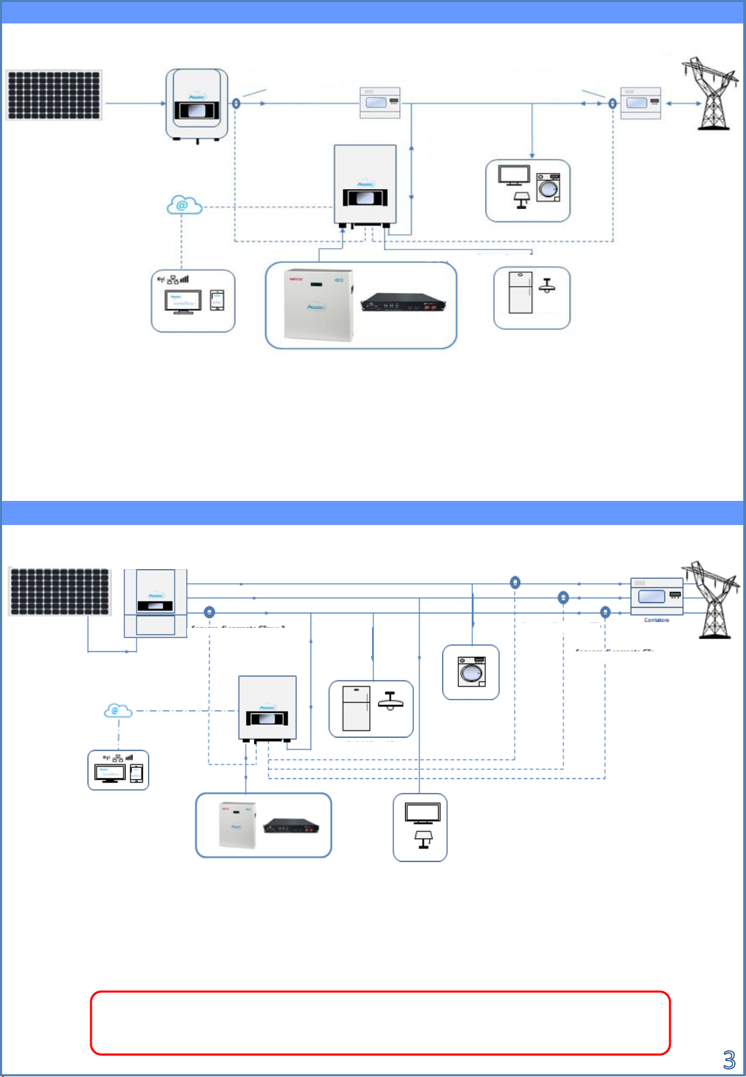
3.3 Grid Connections
In case of a single battery, two power cables (positive and negative) and a communication cable will be connected.
This connection is shown in the figures below:
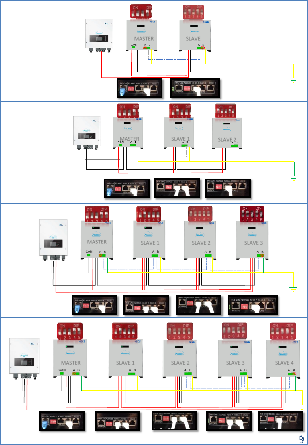
Note: The DIP switch positions must be set according to the factory settings (if
modified accidentally, contact technical support)
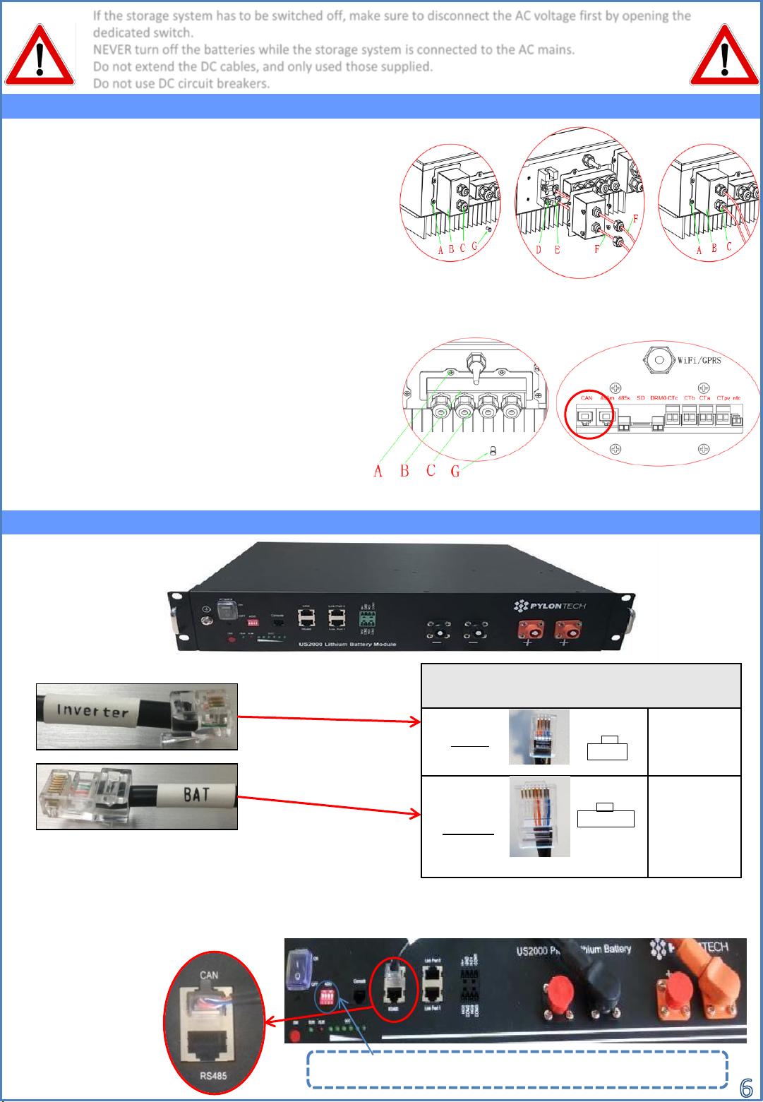
CONNECTING THE POWER CABLES:
1) Unscrew the 4 screws (A) with a screwdriver.
2) Remove the cover (B), loosen the cable gland (C),
and then remove the stopper (G).
3) Feed the battery cables (F) through the cable gland,
then connect them to the positive and negative
terminals of the inverter (E).
4) Replace the cover on the inverter and secure it with
the four screws; then tighten the cable glands.
CONNECTING THE COMMUNICATION CABLES:
1) Unscrew the 4 screws (A) with a screwdriver.
2) Remove the cover (B), loosen the cable gland (C),
and then remove the stopper (G).
3) Feed the communication cable (inverter side)
through the cable gland on the left side of the
cover, then insert the connector into the CAN port
on the inverter's communication board.
4) Replace the cover on the inverter and secure it with
the four screws; then tighten the cable glands.
Note: The communication cable is located inside the
kit in the inverter box.
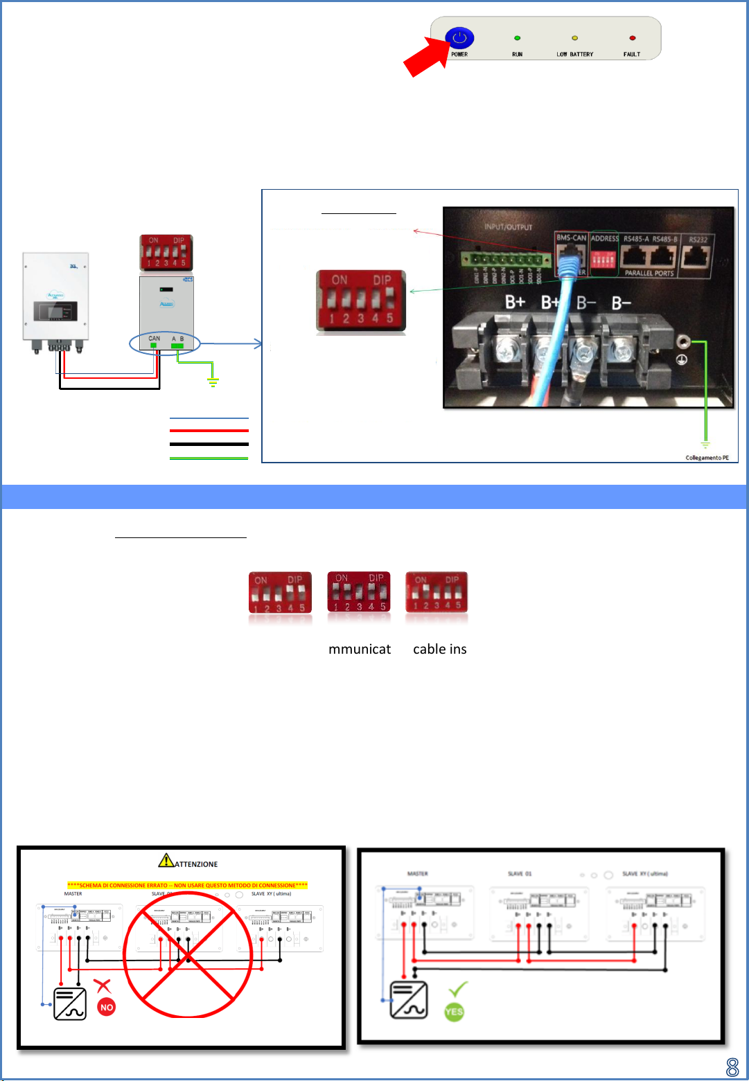
Communication cable pinout between Pylontech
battery & 3000SP system, left to right
PIN 1: White orange
PIN 2: orange
PIN 3: white blue
PIN 4: blue
PIN 1: not used
PIN 2: not used
PIN 3: not used
PIN 4: White orange
PIN 5: orange
PIN 6: not used
PIN 7: white blue
PIN 8: blue
1 … 4
3000SP
Pylontech 1 … 8
The communication
cable must be
connected to the
battery's CAN port
If the storage system has to be switched off, make sure to disconnect the AC voltage first by opening the
dedicated switch.
NEVER turn off the batteries while the storage system is connected to the AC mains.
Do not extend the DC cables, and only used those supplied.
Do not use DC circuit breakers.
Note: Maximum DoD
Programmable 80%
8.1 SINGLE PYLONTECH BATTERY
7. BATTERY CONNECTION