Zeck Audio VECTOR T2A-M User manual

VECTOR
T2A•M

Sehr geehrter Kunde,
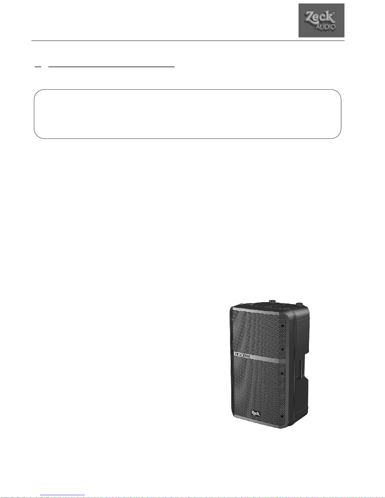
wir freuen uns, daß Sie sich für die Zeck VECTOR T2A•M ent-
schieden haben. Die VECTOR-Serie ist für Audioanwendungen
mit universellen Möglichkeiten konzipiert worden und ist mit
einem Class-AB-Verstärker ausgerüstet, welcher höchste Linea-
rität und Verzerrungsfreiheit bietet. Zusätzlich zeichnet sich die
VECTOR-Serie durch ihre einfache Handhabung und ihr extrem ge-
ringes Gewicht aus.
Wir wünschen Ihnen mit diesem eigenständigen, professionellen
Systembaustein viel Freude, Kreativität und Erfolg!
Lesen Sie diese Bedienungsanleitung bitte aufmerksam durch,
damit Sie die Funktionen und Möglichkeiten dieser Aktivbox schnell
und effektiv nutzen können.
Viel Spaß
Dear customer,
thank you very much for buying our Zeck VECTOR T2A•M
speaker cabinet. The VECTOR series has been designed for
universal and versatile audio application and comes equipped
with two power amplifiers for highest linearity and lowest
possible distortion. All Vector series cabinets combine easy
handling and low weight.
We are sure that this independent professional audio system will
reward you with fun, creativity and success.
Please study the following instructions carefully to become
quickly familiar with all features and functions of this active
speaker cabinet.
Have fun!
Cher client,
Nous nous réjouissons de votre choix pour le VECTOR T2A•M.
Le VECTOR T2A•M a été conçu comme un système de
renforcement sonore universel. Il est équipé d'amplificateurs en
classe AB qui offrent la plus grande linéarité avec une absence
de distorsion audible. La série VECTOR se distingue également
par une manipulation simple et un poids extrêmement faible.
Nous souhaitons que vous puissiez en retirer beaucoup de
plaisir, de créativité et de succès de ce système sonore autonome
et professionnel.
Lisez attentivement cette notice d'utilisation afin de devenir
rapidement familier avec les fonctions et les possibilités de cette
enceinte amplifiée.
Toute l'équipe ZECK Audio
Inhalt Seite
1. Sicherheitshinweise . . . . . . . . . . . . . . . . . . . . . . . .3
2. Ausstattung . . . . . . . . . . . . . . . . . . . . . . . . . . . . . . .3
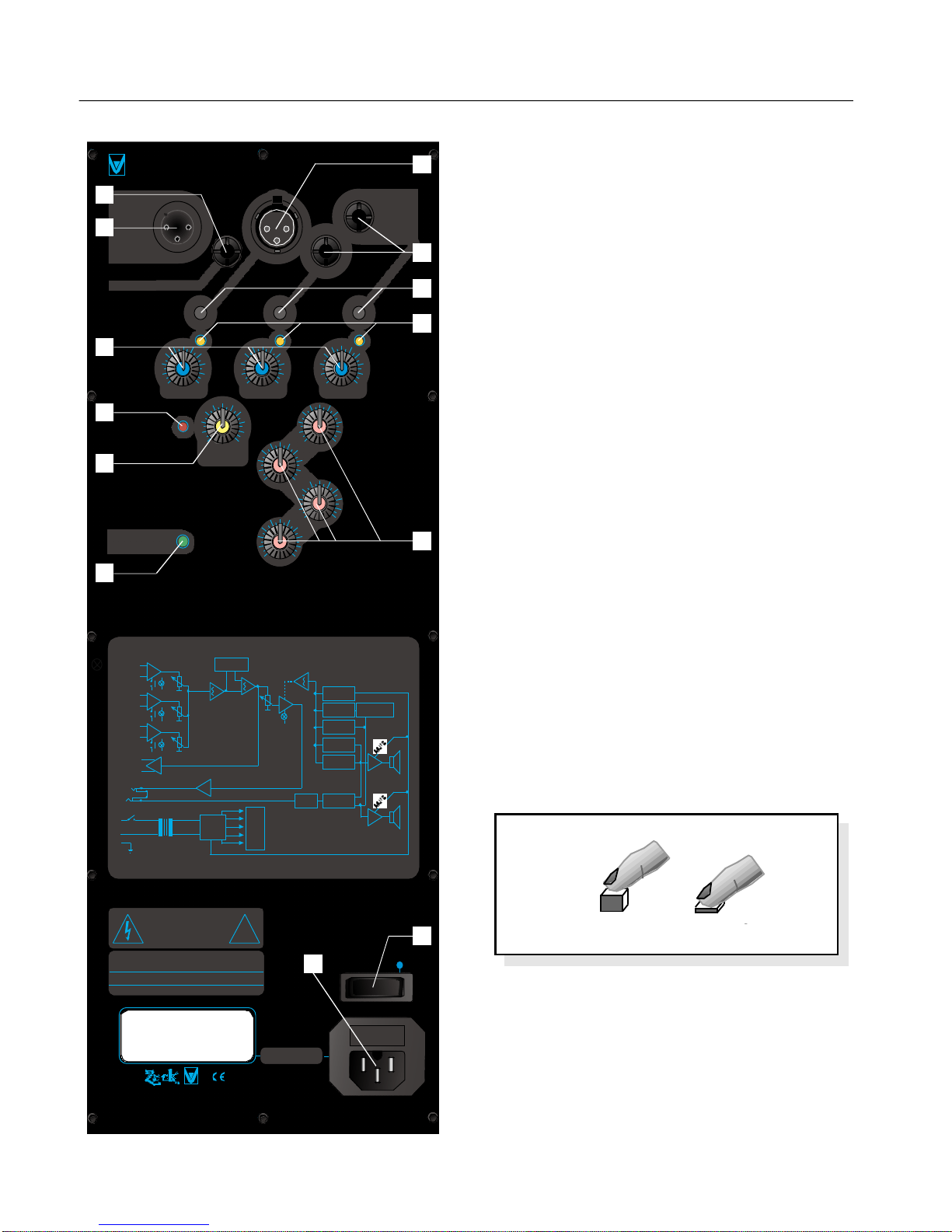
3. Übersicht der Bedienelemente . . . . . . . . . . . . . . .4
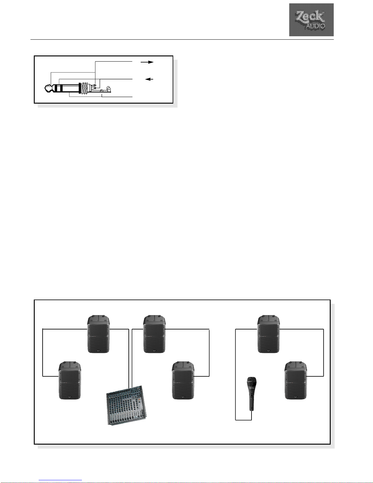
4. Anschlüsse . . . . . . . . . . . . . . . . . . . . . . . . . . . . . . . .5
5. Aktiv-Sektion . . . . . . . . . . . . . . . . . . . . . . . . . . . . .5
6. Modulschacht . . . . . . . . . . . . . . . . . . . . . . . . . . . . .5
7. Technische Daten . . . . . . . . . . . . . . . . . . . . . . . . . .5
8. Hinweise zum Schutz der Lautsprecher . . . . . . . .6
9. Halterungen & Zubehör . . . . . . . . . . . . . . . . . . . . .6
Contents Page
1. Safety instructions . . . . . . . . . . . . . . . . . . . . . . . . .7
2. Features . . . . . . . . . . . . . . . . . . . . . . . . . . . . . . . . . .7
3. Quick reference . . . . . . . . . . . . . . . . . . . . . . . . . . .8
4. Connections . . . . . . . . . . . . . . . . . . . . . . . . . . . . . .8
5. Amplifier section . . . . . . . . . . . . . . . . . . . . . . . . . .9
6. Module cavity . . . . . . . . . . . . . . . . . . . . . . . . . . . . .9
7. Technical specifications . . . . . . . . . . . . . . . . . . . . .9
8. Hints for speaker safety . . . . . . . . . . . . . . . . . . . .10
9. Accessories & mounting hardware . . . . . . . . . . .10
Table des matières Page
1. Instructions de sécurité . . . . . . . . . . . . . . . . . . . . .11
2. Caractéristiques du système . . . . . . . . . . . . . . . . .11
3. Description du système . . . . . . . . . . . . . . . . . . . . .12
4. Connections . . . . . . . . . . . . . . . . . . . . . . . . . . . . . .12
5. Section amplificatrice . . . . . . . . . . . . . . . . . . . . . .12
6. Slot pour modules d'extension . . . . . . . . . . . . . . .13
7. Spécifications techniques . . . . . . . . . . . . . . . . . . .13
8. Directives de protection des haut-parleurs . . . . .13
9. Accessoires et supports . . . . . . . . . . . . . . . . . . . . .14

3
Bedienungsanleitung VECTOR T2A•M © Zeck Audio
VECTOR T2A•M
Bedienungsanleitung
1. Sicherheitshinweise
1. Lesen Sie die Bedienungsanleitung vor Gebrauch der Box aufmerksam durch.
2. Alle Warnhinweise auf der Box und in dieser Anleitung müssen genau beachtet werden.
3. Die Box darf nicht in der Nähe von Wasser (Waschbecken, Badewanne, feuchter Keller, Swimming-Pool usw.)
benutzt werden.
4. Die Box darf nicht in der Nähe von Hitzequellen (z.B. Heizkörpern oder in der prallen Sonne) betrieben werden.
5. Plätze, an denen die Box mit Staub oder Vibrationen konfrontiert ist sollten vermieden werden.
6. Das Eindringen von Gegenständen und Flüssigkeiten in das Gehäuse ist zu vermeiden.
7. Zum Schutz vor elektrischem Schlag dürfen nur solche Netzsteckdosen benutzt werden, bei denen ein Freiste-
hen der Kontakte ausgeschlossen ist.
8. Die Box darf nur mit einer korrekten Schutzerdung betrieben werden, keinesfalls sollte die Schutzerdung un-
terbrochen werden.
9. Das Netzkabel muß so verlegt werden, daß ein Quetschen durch Auftreten oder durch Gegenstände ausge-
schlossen ist. Das Netzkabel ist besonders am Netzstecker und an der Stelle des Geräteeintritts vor mechanischer
Belastung zu schützen.
10. Plätze, an denen die Box eine schräge oder unstabile Unterlage hat, sollten vermieden werden.
11. Der Benutzer darf keine Wartungs- oder Servicearbeiten durchführen.
Alle Wartungs- und Servicearbeiten müssen von qualifiziertem Fachpersonal durchgeführt werden.
12. Bewahren Sie diese Bedienungsanleitung für zukünftiges Nachschlagen auf.
2. Ausstattung
- aktive 2-Weg-Bassreflex-Box
- 50 W Endstufe für den 1“ Treiber
- 150 W Endstufe für den 12“ Tieftöner
- Automatische elektronische Limiter für beide Aktivwege
- Trennfrequenz bei 1,8 kHz
- Integrierte Mischersektion
- 3 Symmetrische Eingänge (1x XLR / 2x Stereoklinke)
- Alle Eingänge MIC/LINE schaltbar
- Insert-Buchse
- VOLUME-Steller
- Limit-LED
- Netzschalter
- Netzbuchse
- Hochständerflansch mit Feststellschraube
ACHTUNG !
Dieses Produkt kann zu Hörschäden führen. Betreiben Sie diese Aktivbox niemals mit einem Lautstärkepegel, der als un-
angenehm empfunden wird. Wenn Sie ein unangenehmes, dumpfes Gefühl in den Ohren spüren oder Ihr Hörvermögen
nachläßt, wenden Sie sich an einen Arzt.

4Bedienungsanleitung VECTOR T2A•M © Zeck Audio
3. Übersicht der Bedienelemente
1 Insert-Buchse (Stereoklinke)
2 Balanced Output (XLR male)
3 Balanced Input 1 (XLR female)
4 Balanced Input 2&3 (Stereoklinke)
5 MIC/LINE Schalter 1-3
6 ‘MIC’ LED 1-3
7 Level 1-3
8 ‘Limit’ LED
9 MASTER VOLUME Steller
10 4-Band Equalizer
11 ‘POWER ON’ LED
12 An/Aus Schalter
13 Netzanschlussbuchse
4. Anschlüsse (Abb.3)
Eingang:
Der symetrische XLR-Eingang „BALANCED INPUT 1 (2)“
und die 2 Stereoklinken Eingänge 2 & 3 (3) können von
einem Mikrofon- oder Line-Signal gespeist werden. Über
die „MIC/LINE-Schalter 1-3 (5)“ kann der Eingang an
die jeweilige Signalquelle (Mic. Bzw. Line-Signal) ange-
paßt werden. Um die Bedienung übersichtlich zu gestal-
ten leuchtet im „Line“-Betrieb die „MIC-LED´s 1-3 (6)“
auf, im „Mic“-Betrieb sind diese aus. (Abb. 1).
„LINE“ „MIC“
Ausgang:
Der symmetrische XLR-Ausgagang „BALANCED OUTPUT
(2)“ ermöglicht das Verbinden von mehreren Systemen
(z.B. dem Subwoofer Zeck VECTOR S3A oder anderen
Aktivsystemen von Zeck ).
Insert:
Über die „INSERT-Buchse (1)“ können externe Effekt-
geräte an die T2A•M angeschlossen werden. Diese Stereo-
Klinkenbuchse beinhaltet gleichzeitig den Send- und
Returnweg (Abb. 2).
Abb. 1
THIS APPARATUS MUST BE EARTHED. TO REDUCE THE
RISK OF FIRE OR ELECTRIC SHOCK DO NOT EXPOSE
THIS APLLIANCE TO RAIN OR MOISTURE.
NO USER SERVICEABLE PARTS INSIDE.
REFER SERVICING TO QUALIFIED PERSONNEL.
RISQUE DE CHOC ELECTRIQUE. NE PAS OUVRIR.
RISK OF ELECTRIC SHOCK
DO NOT OPEN
CAUTION
!
INPUTS
INPUT 1
INPUT 2
INPUT 3
BALANCED
OUT
TOROIDAL
ISOLATION
TRANSFORMER
MAINS
MODULE
LEVEL
VCA
MAIN
LEVEL
POWER ON
RAMP
GENERATOR
LF SPEAKER
PROTECTION LF SPEAKER
IMP.SIMMULATION
HF DRIVER
PROTECTION
LF CLIP
DETECTOR
HF CLIP
DETECTOR HF
AMP
LF
AMP
HF
LF
EQ +
TIME ALIGN
TONE
CONTROL
POWER
SUPPLY
+25 V
-25 V
+15 V
-15 V
0
POWER ON DETECTOR
INSERT
MIC/LINE
MIC/LINE
MIC/LINE
BALANCED
BALANCED
BALANCED
LIMIT
(TIP- SEND)
(RING - RETURN)
1. 2.
2
1
4
3
5
6
9
10
11
12
13
7
8

5
VECTOR T2A•M
Bedienungsanleitung VECTOR T2A•M © Zeck Audio
5. Aktivsektion
Endstufen:
Die 50W Treiber-Endstufe und die 150 W Class-AB-Tieftö-
ner-Endstufe sind bei einer Trennfrequenz von 1,8 kHz abge-
koppelt. Durch die interne optimale Einstellung der Trenn-
frequenz sind weitere Einstellungsarbeiten nicht mehr not-
wendig.
Limiter:
Die elektronischen Limiter funktionieren in beiden Aktivwe-
gen automatisch. Sobald sie im Einsatz sind leuchtet die
„LIMIT-LED (8)“ auf. In diesem Fall sollte das Eingangssignal
soweit zurückgenommen werden, daß die LED
gerade nicht mehr leuchtet.
Steller:
Durch den „MASTER VOLUME-Steller (9)“ kann die Laut-
stärke eingestellt werden.
Mischer:
Die Eingangspegel der Eingänge „Balanced Input 1-3
(2/3)“ können über die Steller „Level 1-3 (7)“ einge-
stellt und abgemischt werden.
Durch einen „4-Band Equalizer (10)“ kann das Mastersig-
nal in den Bereichen „Low“ bei 70Hz, „Mid-Low“ bei 600Hz,
„Mid-High“ bei 2,5kHz und „High“ bei 10kHz um 12dB
abgesenkt bzw. angehoben werden.
Netzanschluss:
Über den „MAIN INPUT (13)“ wird das Gerät an das Netz
(230V / 50Hz) angeschlossen. Der „POWER ON-Schalter
(12)“ schaltet das Gerät ein. Sobald die „POWER ON-LED
(11)“ leuchtet, ist die T2A•M funktionsbereit.
6. Modulschacht
Der Modulschacht ermöglicht das Einbauen von zusätzlichen
Modulen wie: Line-Delay und Monitor-Modul sowie das
Drahtlos-System Zeck d.a.i.sy.
7. Technische Daten
Integrierter Verstärker für 12“
Leistung . . . . . . . . . . . . . . . . . . . . . . . . . . . . . . . . . .150W RMS
Klirrfaktor . . . . . . . . . . . . . . . . . . . . . . . . . . . . . . . . . . . .< 0,1%
Integrierte Treiberendstufe für 1“
Leistung . . . . . . . . . . . . . . . . . . . . . . . . . . . . . . . . . . .50W RMS
Klirrfaktor . . . . . . . . . . . . . . . . . . . . . . . . . . . . . . . . . . . .< 0,1%
Schalldruck max. cont. . . . . . . . . . . . . . . . . . . . . . . . . . .121dB
Frequenzumfang . . . . . . . . . . . . . . . . . . . . . . . . .55Hz - 20kHz
Abstrahlwinkel (Treiber) . . . . . . . . . . . . . . . . . . . . . . .90 x 75°
Trennfrequenz . . . . . . . . . . . . . . . . . . . . . . . . .1,8kHz (active)
Abmessungen (B x H x T) . . . . . . . . . . . . . . . .39 x 62 x 31,2cm
Gewicht . . . . . . . . . . . . . . . . . . . . . . . . . . . . . . . . . . . . . . .18kg
Abb. 2
Abb. 3
TIP - „Send“
RING „Return“
Sleeve „Ground“
L R
Balanced
Inputs Balanced
Input
Balanced
Input
Balanced
Output
Balanced
Input
Balanced
Input
Balanced OutputBalanced Output
VECTOR
S3A VECTOR
S3A VECTOR
S3A
VECTOR
T2A•M
VECTOR
T2A•MVECTOR
T2A•M

6
8. Hinweise zum Schutze der
Lautsprecher
folgende Situationen sollten vermieden werden:
- Akustische Rückkopplung über Mikrofone
- Anhaltend verzerrte Signale hoher Leistung
- Popp-Geräusche, die bei aktivierter Box entstehen, wenn
Geräte der Anlage eingeschaltet, angeschlossen oder
abgetrennt werden.
9. Halterungen & Zubehör
VECA1: Kippschutz für Monitoranwendung
Dieser steckbare Kunststoff-Fuß gibt der Box bei
Monitoranwendung einen stabilen Halt.
VEC12M1: Montagebügel für
vertikale Positionierung
Diese robuste Halterung wird
direkt an die Decke montiert.
VEC12M2:
Montagebügel für Längsachse
Diese robuste Halterung kann
direkt an die Wand oder die Decke
montiert werden.
Mit Hilfe des Montageadapters
VEC12M3 kann dieser Montage-
bügel z.B. an Traversen befestigt
werden. Dadurch wird ein Schwen-
ken um die Längsachse
ermöglicht.
Mit Hilfe des Montageadapters
VEC12M4 kann dieser Montagebü-
gel auf einem Boxenhochständer be-
festigt werden. Dadurch wird ein
Schwenken um die Querachse er-
möglicht.
VEC12M5: Wandhalterung
Diese Halterung wird mit Schrau-
ben an der Wand befestigt und er-
möglicht das Schwenken in zwei
Richtungen.
M10: Ringschraube
Diese stabile Metall-Öse dient als
zusätzliche Sicherung bei geflogenen
VECTOR-Systemen.
VEC12COVER: Schutzhülle
Bedienungsanleitung VECTOR T2A•M © Zeck Audio

7
VECTOR T2A•M
Owner’s manual VECTOR T2A•M © Zeck Audio
Operational instructions
1. Safety instructions
1. Before using the VECTOR T2A•M, study the instructions in this manual carefully.
2. All safety instructions in this manual and on the cabinet have to be strictly followed.
3. Never use the VECTOR T2A•M near water or in a humid environment, e.g. near washbasins, bath tubs, swimming pools
or in damp rooms.
4. Never use the VECTOR T2A•M near heat sources (e.g. radiators) or in intense sunlight.
5. Environments where the VECTOR T2A•M is exposed to dust or vibrations should be avoided.
6. Do not allow objects or liquids to enter the cabinet.
7. For protection against electric shock, use only mains sockets that are absolutely proof against protruding contacts.
8. The VECTOR T2A•M must always be used with functioning protective earth. Never defeat or manipulate the protective
earth means of the VECTOR T2A•M.
9. Always run the mains cable so that any danger of damage, e.g. by pinching objects, is absolutely excluded. In
particular, protect both ends of the mains cable against excessive tension.
10. Do not place the VECTOR T2A•M on surfaces that are tilted and/or unstable.
11. As a user, do not attempt to service the VECTOR T2A•M. Leave all repair work to qualified personell. Zeck is no liable
for any damage as a result of unauthorized service performance.
12. Keep the entire instruction manual for future reference.
2. Features
- Active 2-way bass reflex cabinet
- 50W power amplifier for 1“ tweeter
- 120W power amplifier for 12“ woofer
- Automatic electronic limiter for both drivers
- 1.8kHz crossover frequency
- Integrated mixer section
- 3 balanced inputs, 1 x XLR, 2 x stereo jack
- All inputs switchable for MIC or LINE operation
- Insert jack
- Master volume control
- Limiter LED
- Mains power switch
- Mains connector
- High-stand adaptor socket with locking screw
Attention!
This device has the potential of causing hearing damage. Never operate this device at volumes that listeners might
perceive as irritating. If you experience an uncomfortable and dull feeling in your ears or suffer from hearing loss,
contact a physician.

8Owner’s manual VECTOR T2A•M © Zeck Audio
3. Quick reference
1 Insert jack (1/4“ stereo jack)
2 Balanced output (XLR male)
3 Balanced input #1 (XLR female)
4 Balanced input #2 and #3 (1/4“ stereo jack)
5 MIC/LINE switch for channels 1-3
6 ‘MIC LED’ for channels 1-3
7 Level controls for channels 1-3
8 ‘Limit’ LED
9 Master volume control
10 4-Band equalizer
11 ‘Power On’ LED
12 Power switch
13 Mains input socket
4. Connections (Fig. 3)
Inputs:
The XLR input (3) and both 1/4“ inputs (4) accept balanced
or unbalanced signals and can be switched for high-level
(Line) or low-level (Microphone) operation with their
correspondent MIC/LINE switch (5). A bright MIC LED (6)
indicates that line input level has been selected for the
correspondent input (Fig 1).
Output:
The BALANCED OUTPUT (2) allows for easy linking of
several VECTOR system cabinets, e.g. Zeck VECTOR S3A
subwoofer, or other active cabinets by Zeck.
Insert jack:
The INSERT jack (1) allows to connect external effect
devices to the T2AM. This 1/4“ stereo jack provides
both send and return connections (Fig. 2)
Fig. 1
THIS APPARATUS MUST BE EARTHED. TO REDUCE THE
RISK OF FIRE OR ELECTRIC SHOCK DO NOT EXPOSE
THIS APLLIANCE TO RAIN OR MOISTURE.
NO USER SERVICEABLE PARTS INSIDE.
REFER SERVICING TO QUALIFIED PERSONNEL.
RISQUE DE CHOC ELECTRIQUE. NE PAS OUVRIR.
RISK OF ELECTRIC SHOCK
DO NOT OPEN
CAUTION
!
INPUTS
INPUT 1
INPUT 2
INPUT 3
BALANCED
OUT
TOROIDAL
ISOLATION
TRANSFORMER
MAINS
MODULE
LEVEL
VCA
MAIN
LEVEL
POWER ON
RAMP
GENERATOR
LF SPEAKER
PROTECTION LF SPEAKER
IMP.SIMMULATION
HF DRIVER
PROTECTION
LF CLIP
DETECTOR
HF CLIP
DETECTOR HF
AMP
LF
AMP
HF
LF
EQ +
TIME ALIGN
TONE
CONTROL
POWER
SUPPLY
+25 V
-25 V
+15 V
-15 V
0
POWER ON DETECTOR
INSERT
MIC/LINE
MIC/LINE
MIC/LINE
BALANCED
BALANCED
BALANCED
LIMIT
(TIP- SEND)
(RING - RETURN)
1.
+
2.
2
1
4
3
5
6
9
10
11
12
13
7
8
„LINE“ „MIC“

5. Amplifier section
Power amplifiers:
The 50 W amplifier for the tweeter and the 150W amplifier
for the woofer are driven by an integrated active crossover
which has a separation frequency of 1.8kHz. This crossover
has been optimized for the speaker configuration of the
VECTOR T2AM and requires no further adjustments.
Limiters:
Every amplifier has its own automatic limiter. The LIMIT LED
becomes lit as soon as one limiter is active. In this case, the
level(s) of the input signal(s) should be reduced until the LED
remains dark.
Controls:
The MASTER VOLUME control (9) allows to adjust the overall
cabinet volume.
Mixer section:
Each input can be individually level-adjusted with its
correspondent LEVEL control (7).
The sound of the mixed signal can be adjusted with the 4-
band master equalizer (10). Each of the following
frequencies can be boosted or attenuated by ±12dB: Low
(70Hz), Low Mid (600Hz), High Mid (2.5kHz) and High
(10kHz).
Mains connection:
The cabinet must be connected to a 220V/50Hz power
supply via the MAINS INPUT (13). The unit can be switched
on and off with the POWER ON switch (12). The T2AM is
ready for operation when the POWER ON LED (11) is bright.
6. Module cavity
The VECTOR T2AM has a module cavity for plug-in installati-
on of optional audio modules, such as line delays, monitor
modules or a d.a.i.sy wireless system by Zeck.
7. Technical specifications
Integrated amplifier for 12“ speaker
Output power . . . . . . . . . . . . . . . . . . . . . . . . . .150W RMS
Distortion . . . . . . . . . . . . . . . . . . . . . . . . . . . . . . . . . .<0,1%
Integrated amplifier for 1“ tweeter
Output power . . . . . . . . . . . . . . . . . . . . . . . . . . .50W RMS
Distortion . . . . . . . . . . . . . . . . . . . . . . . . . . . . . . . . . .<0,1%
Sound pressure level, max-cont. . . . . . . . . . . . . . . . .121dB
Frequency range . . . . . . . . . . . . . . . . . . . . . .55Hz - 20kHz
Coverage (tweeter) . . . . . . . . . . . . . . . . . . . . . . . .90° x 75°
Crossover frequency . . . . . . . . . . . . . . . . . .1.8kHz (active)
Dimensions (w x h x d) . . . . . . . . . . . . .390 x 620 x 312cm
Weight . . . . . . . . . . . . . . . . . . . . . . . . . . . . . . . . . . . . .18kg
9
VECTOR T2A•M
Owner’s manual VECTOR T2A•M © Zeck Audio
Fig. 3
L R
Balanced
Inputs Balanced
Input
Balanced
Input
Balanced
Output
Balanced
Input
Balanced
Input
Balanced OutputBalanced Output
VECTOR
S 3A VECTOR
S 3A VECTOR
S 3A
VECTOR
T2A•M
VECTOR
T2A•M VECTOR
T2A•M
Fig. 2 TIP „Send“
RING „Return“
Sleeve „Ground“

10 Owner’s manual VECTOR T2A•M © Zeck Audio
8. Hints for speaker safety
For prolonged speaker protection, the following situation
should be avoided:
- acoustic feedback through microphones
- prolonged distorted sounds at high levels
- switching noise from other equipment that is connected to
and/or operatzed with the VECTOR T3A
9. Accessories & mounting
hardware
VECA1: Tilt protection for monitor use
This plug-in plastic foot cares for
stable operation of the VECTOR
T3A in monitor position.
VEC12M1: Mounting bracket
for vertical positioning
Rugged fixture, mounts
directly to walls.
VEC12M2: Mounting bracket for
horizontal postioning
Rugged fixture, mounts directly
to walls.
If an additonal VEC12M3 adaptor
is used, this bracket can be directly
fixed to truss systems or similar
setups. It also allows for horizontal
panning of the cabinet.
If an additonal VEC12M4 adaptor
is used, this bracket can be used
directly on a high-stand. It also
allows for vertical tilting of the
cabinet.
VEC12M5: Wallmount adapter
This fixture is attached to walls
with two screws and allows for
tilting of the cabinet in two directions.
M10: Fly-mount eyelet
This heavy-duty eyelet serves as an
additional protection when the VECTOR T3A
is flown.
VEC12COVER: Protective cover

Notice d'utilisation
Instructions de sécurité
1. Lisez attentivement la notice d'utilisation avant toute utilisation.
2. Toutes les indications d'attention contenues dans cette notice ou sur l'enceinte doivent être suivies scrupuleusement.
3. L'enceinte ne doit pas être utilisée à proximité d'eau ( bassine d'eau, baignoire, cave humide, piscine, etc.)
4. L'enceinte ne doit pas être utilisée à proximité de source de chaleur, un radiateur par exemple.
5. Il faut éviter les endroits où l'enceinte peut subir des vibrations ou de la poussière.
6. Il faut éviter l'entrée de tout corps solide ou liquide dans l'enceinte.
7. N'utiliser que des prises électriques protégées afin d'éviter toute électrocution.
8. L'appareil ne doit être utilisé que correctement raccordé à un réseau de terre. En aucun cas la ligne de terre doit être
interrompue.
9. Le câble d'alimentation électrique doit être protégé de toute possibilité de percement, pincement ou cisaillement par un
objet quelconque. Une protection contre l'emmêlement dans les pieds est également nécessaire. Il est particulièrement
important d'éviter toute contrainte mécanique aux passages de câbles et à la prise secteur.
10. Eviter de placer les enceintes sur des surfaces obliques ou instables.
11. Aucune maintenance ou réparation ne doit être effectuée par l'utilisateur. Toute maintenance ou réparation ne doit
être effectuée que par un technicien qualifié.
12. Conservez ces instructions pour utilisation ultérieure.
2. Caractéristiques du système
- Enceinte amplifiée 2 voies avec résonateur (bass-reflex)
- Amplificateur de 50W pour la chambre 1"
- Amplificateur de 150W pour le haut-parleur de grave de 30cm (12")
- Limiteur électronique automatique dans les deux voies actives
- Fréquence de recouvrement à 1,8kHz
- Mélangeur intégré
- 3 entrées symétriques (1 x XLR / 2 x 'Jacks' stéréos)
- Toutes entrées commutables micro/ligne
- Prise d'insert (Jack stéréo)
- Bouton de volume
- Diodes LED de limitation
- Interrupteur secteur
- Prise secteur
- Châssis rigide avec fixations rapides
11
VECTOR T2A•M
Mode d’emploi VECTOR T2A•M © Zeck Audio
ATTENTION!
Ce produit peut causer des troubles et dommages auditifs dépendants de son utilisation.
N'amenez jamais la pression sonore produite par cette enceinte active à des niveaux qui sont ressentis désagréablement.
Si vous percevez une sensation auditive désagréable ou sourde dans les oreilles, ou si votre acuité auditive baisse, allez
consulter un médecin.

3. Description du système /
éléments fonctionnels.
1 "INSERT" = insert via 'Jack' stéréo
2 "BALANCED OUTPUT" = sortie symétrique
(XLR mâle)
3 "BALANCED INPUT 1" = Entrée symétrique
(XLR femelle)
4 "BALANCED INPUT 2 & 3" = Entrée symétrique
('Jacks' stéréos)
5 "MIC / LINE" = interrupteurs micro / ligne 1 à 3
6 "MIC-LED" = Diodes de mode microphone 1 à 3
7 Boutons de réglage du volume 1 à 3
8 Diodes indiquant le fonctionnement des limiteurs
9 Réglage du volume général
10 Egaliseur 4 bandes
11 Diode de mise sous tension
12 Interrupteur secteur
13 Prise secteur
4. Connections (Fig. 3)
Entrée:
Les entrées symétriques par XLR "BALANCED INPUT 1" (3)
ou par les 'Jacks' stéréos 2 & 3 (4) peuvent être alimentées
par un signal de niveau ligne ou niveau microphone.
L'interrupteur "MIC / LINE 1-3" (5) permet d'indiquer au
système le type de signal entrant. Afin de donner une vue
globale du fonctionnement, les diodes "MIC-LED 1-3"
s'allument en mode 'ligne', alors qu'elles restent éteintes
en mode bas niveau (micro) (Fig. 1).
Sortie:
La sortie symétrique par XLR "BALANCED OUTPUT" (2)
autorise le chaînage de plusieurs systèmes (par ex. un
'Subwoofer' Zeck VECTOR S3A, ou un autre système actif
Zeck).
12 Mode d’emploi VECTOR T2A•M © Zeck Audio
Fig. 1
THIS APPARATUS MUST BE EARTHED. TO REDUCE THE
RISK OF FIRE OR ELECTRIC SHOCK DO NOT EXPOSE
THIS APLLIANCE TO RAIN OR MOISTURE.
NO USER SERVICEABLE PARTS INSIDE.
REFER SERVICING TO QUALIFIED PERSONNEL.
RISQUE DE CHOC ELECTRIQUE. NE PAS OUVRIR.
RISK OF ELECTRIC SHOCK
DO NOT OPEN
CAUTION
!
INPUTS
INPUT 1
INPUT 2
INPUT 3
BALANCED
OUT
TOROIDAL
ISOLATION
TRANSFORMER
MAINS
MODULE
LEVEL
VCA
MAIN
LEVEL
POWER ON
RAMP
GENERATOR
LF SPEAKER
PROTECTION LF SPEAKER
IMP.SIMMULATION
HF DRIVER
PROTECTION
LF CLIP
DETECTOR
HF CLIP
DETECTOR HF
AMP
LF
AMP
HF
LF
EQ +
TIME ALIGN
TONE
CONTROL
POWER
SUPPLY
+25 V
-25 V
+15 V
-15 V
0
POWER ON DETECTOR
INSERT
MIC/LINE
MIC/LINE
MIC/LINE
BALANCED
BALANCED
BALANCED
LIMIT
(TIP- SEND)
(RING - RETURN)
1.
+
2.
2
1
4
3
5
6
9
10
11
12
13
7
8
Ligne Micro

Insert:
La prise "INSERT" (1) est le point d'insertion d'effet du
VECTOR T2A*M.
La prise 'Jack' stéréo contient à la fois le départ et le retour
d'effet ( pointe = départ, bague = retour, voir Fig. 2).
5. Section amplificatrice
Amplificateur de puissance:
L'amplificateur de 50W pour la chambre de compression 1"
et l'amplificateur des graves de 150W sont en classe AB et
sont alimentés via un filtre séparateur à 1,8kHz. Ce réglage
interne de la fréquence de séparation évite d'autres travaux
ultérieurs de mise au point.
Limiteur:
Les deux voies actives sont équipées de limiteurs
automatiques. En cas d'entrée en action du limiteur, la diode
"LIMIT-LED" (8) s'allume. Le niveau du signal d'entrée est
dans ce cas automatiquement réduit jusqu'à l'extinction de
la diode.
Boutons de réglages:
Le bouton "MASTER VOLUME" (9) permet d'ajuster le niveau
sonore global.
Mélangeur:
Les niveaux des entrées "BALANCED INPUT 1-3" (2/3)
peuvent être ajustés et mélangés avec les boutons
"LEVEL 1-3" (7).
Le signal principal peut être corrigé de ±12dB par l'égaliseur
4 bandes "4 BAND EQUALIZER" (10) dont les bandes sont
centrées sur 600Hz "MID-LOW", sur 2,5kHz "MID-HIGH", et
articulés aux extrémités sur 70Hz "LOW" et 10kHz "HIGH".
Raccordement secteur:
L'on raccorde l'appareil au secteur (230V/50Hz) via la prise
"MAIN INPUT" (13). L'interrupteur "POWER ON" (12) permet
de mettre le système sous tension. Le système est
opérationnel dès que la diode "POWER ON-LED" (11) est
allumée.
6. 'Slot' pour module d'extension
Ce 'slot' permet l'installation de modules comme: une ligne à
retard, un module de contrôle ou un récepteur sans fil ZECK
d.a.i.s.y.
7. Spécifications techniques
Ampli intégré pour le 30 cm (12")
Puissance de sortie . . . . . . . . . . . . . . . . . . . . . . . . . . .150W
Distorsion harmonique totale . . . . . . . . . . . . . . . . .<0,1%
Ampli intégré pour la chambre 1“
Puissance de sortie . . . . . . . . . . . . . . . . . . . . . . . . . . . .50W
Distorsion harmonique totale . . . . . . . . . . . . . . . . .<0,1%
Pression sonore max. continue . . . . . . . . . . . . . . . . .123dB
Bande passante . . . . . . . . . . . . . . . . . . . . . . .55Hz - 20kHz
Angle d’ouverture (aigu) . . . . . . . . . . . . . . . . . . . .90° x 75°
Fréquence de raccordement . . . . . . . . . . . . .1,8kHz (actif)
Dimensions (l x h x p) . . . . . . . . . . . . . . . .39 x 62 x 31,2cm
Masse . . . . . . . . . . . . . . . . . . . . . . . . . . . . . . . . . . . . . .19kg
13
VECTOR T2A•M
Mode d’emploi VECTOR T2A•M © Zeck Audio
Fig.3
G D
Entrées
symétriques Entrée
symétrique
Entrée
symétrique
Sortie
symétrique
Entrée
symétrique
Entrée
symétrique
Sortie symétriqueSortie symétrique
VECTOR
S3A VECTOR
S3A VECTOR
S3A
VECTOR
T2A•M
VECTOR
T2A•M VECTOR
T2A•M
Abb.2 pointe départ
bague retour
corps masse

8. Directives de protection des
haut-parleurs
Les situations suivantes devront être évitées:
- Accrochage ('feed-back') acoustique avec les microphones
(Larsen)
- Maintient d'un signal distordu de forte puissance
- Claquements dus à l'amplification de perturbations induites
par la mise en ou hors service ou de déconnexion d'autres
appareils.
9. Accessoires et supports
VECA 1: Dispositif anti-renversement pour
application de retour de scène (Wedge).
Cette cale synthétique enfichable donne une
assise stable en utilisation comme
retour de scène.
VEC12M1: Equerre de montage
pour positionnement vertical
Ce support robuste est
directement fixé au plafond.
VEC12M2: Equerre de montage
pour positionnement horizontal
Ce support robuste est directement
fixé au mur ou au plafond.
Adaptateur VEC12M3:
on peut utiliser cette équerre de
montage sur une traverse. Un
basculement autour de l'axe
longitudinal est alors rendu
possible par le montage.
Adaptateur VEC12M4:
on peut utiliser cette équerre de
montage sur un pied d'enceinte. Ce
montage autorise un basculement
autour de l'axe horizontal.
VEC12M5: Support mural
Ce support se fixe directement sur
un mur à l'aide de vis. Il autorise
une rotation dans deux directions.
Oeillet fileté M 10:
Ce solide oeillet en métal permet une
sécurisation des éléments du système
VECTOR en cas d'accrochage aérien.
VEC12COVER: housse de protection. Cette
housse synthétique protège l'enceinte
VECTOR des égratignures et des dommages.
14 Mode d’emploi VECTOR T2A•M © Zeck Audio

Garantie über 2 Jahre
Warranty certificate over 2 years
Garantie 2 ans
Kaufdatum Typ Ser. Nr.
Date of purchase Model Ser. No.
Date d’achat Type No. de série:
Name, Anschrift des Käufers Stempel des Händlers
Name, adress of buyer Dealer’s stamp
Nom, adress du client Cachet du revendeur
Die von Zeck geleistete Garantie gilt nur für Geräte, die über autorisierte Zeck-Fachhändler vertrieben
werden. Diese Karte hat nur Gültigkeit, wenn sie vom Händler abgestempelt wird.
This warranty is voided if your device is not purchased from an authorized Zeck dealer or does not have
the dealer’s stamp on it.
La garantie accordée par Zeck ne s’applique que sur du matériel distribué par des points de vente agréés.
Uniquement valable avec le cachet du revendeur.
Karte sorgfältig aufbewahren Keep this document Carte à conserver soigneusement
Zeck Audio • Turnhallenweg 6 • D-79183 Waldkirch
Prüf-Zertifikat
Test certificate
Certificat de contrôle
Gehäuse Phase
Encloser Polarity
Boîtier Phase
Verkabelung Frequenzgang
Wiring Frequency response
Câblage Bande passante
Funktion Impedanz
Performance check Impedance
Test de fonctionnement Impédance
Prüfer: Prüfer:
Tested by: Tested by:
Contrôleur: Contrôleur:
AUDIO

Zeck Audio • Turnhallenweg 6 • D-79183 Waldkirch •Tel.: 0 76 81 /20 04-0 •Fax: 0 76 81 / 20 04-43
Table of contents
Languages:
Other Zeck Audio Stereo System manuals