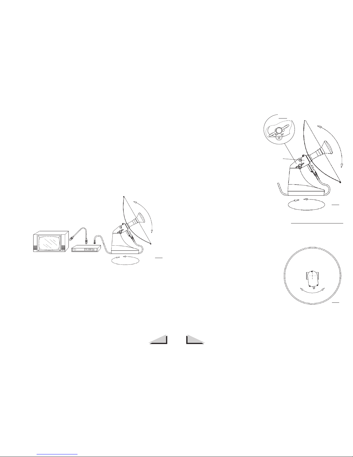
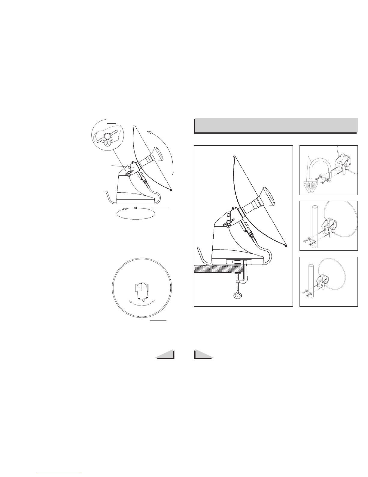
Zehnder Rittling AX 40 User manual

Satelliten-Antenne
Satellite Receiving System
Bedienungsanleitung
Operating Manual
Vorwort
2
Mit dem Kauf der Satellitenantenne MULTIMO haben Sie sich für eine
leistungsstarke kompakte Antenne entschieden.
Sie wurde speziell für den Empfang der Satelliten analogen und
digitalen Programme von ASTRA im mobilen Einsatz konzipiert. Sie
eignet sich aber auch für Programme von z.B. HOTBIRD, TELECOM,
Hispasat und andere innerhalb der starken Ausleuchtzonen.
Die MULTIMO ist eine Einteilnehmerantenne für den Empfang von
vertikal und horizontal polarisierten Signalen (bedingt auch für
zirkulare Polarisation) im Frequenzbereich von 10,7 GHz bis 12,75
GHz. Über ein 22kHz Steuersignal kann zwischen dem LOW- und
HIGH-Band umgeschaltet werden.
Die MULTIMO bietet zusammen mit dem angebotenen Zubehör eine
Vielzahl an Einsatzmöglichkeiten.
Die folgenden Kapitel sollen das Aufstellen und Ausrichten der
MULTIMO erleichtern. Um optimale Empfangseigenschaften zu er-
reichen, beachten Sie die folgenden Kapitel in der Reihenfolge:
Sicherheitshinweise
Standort
Elevationswinkel
TV-Kanal einstellen
Feineinstellung
Polarisationsentkopplung
Befestigungsmöglichkeiten
Technische Daten
Standorttabelle
Garantie
D
analog +
digital
AX 40

Sicherheitshinweise Standort und Inbetriebnahme
4
3
Bitte behandeln Sie die Antenne vorsichtig! Sie wurde mit hoher
Präzision gefertigt und darf nicht verbogen oder beschädigt werden.
Die sehr guten Empfangseigenschaften würden darunter leiden.
Sicherheit bei der Aufstellung:
Wird die MULTIMO mit der Schraubzwinge beispielsweise an einem
Balkongeländer befestigt, muß von Zeit zu Zeit der feste Sitz geprüft
werden.
Für Schäden, die durch eine unzureichende Befestigung entstehen,
übernehmen wir keine Haftung.
Bei stürmischem Wind empfehlen wir die Herausnahme der Antenne
aus dem Standfuß und die feste Montage der MULTIMO mit Hilfe der
Mast- oder der Wandhalterung.
(siehe Kapitel Befestigungsmöglichkeiten)
Blitzschutz:
Bei Unterdach- oder Fenstermontage ist keine Erdung erforderlich,
wenn der höchste Punkt der Antenne mindestens 2 m unterhalb der
Dachrinne und der äußerste Punkt nicht mehr als 1,5 m von der
Außenwand entfernt liegt.
Bei Überdachmontage ist eine Erdung des Antennenstandrohres
vorzunehmen. Auskunft über die korrekte Erdung geben die VDE-
Richtlinien 0855 und die allgemeinen Blitzschutzbestimmungen.
Ihr Fachhändler kennt sich aus und informiert gern über die zu
treffenden Maßnahmen.
Die MULTIMO ist vollständig montiert. Das erleichtert sehr die
Inbetriebnahme . Werkzeug wird nicht benötigt.
Die folgenden Skizzen zeigen wie Sie bei der Inbetriebnahme der
MULTIMO vorgehen sollen.
Die Standorttabelle erleichtert das Einstellen von Elevation und Azimut.
Sie gibt Auskunft über die Werte für den jeweiligen Standort.
Beispiel: Standort in der Nähe von Ulm
Elevation 33,7° -- Azimut 12,2°
Elevation: wie hoch der Satellit steht, Winkel
Azimut: Angabe der Richtung, Süden: ca. 10° in
Deutschland Sonnenstand 12 Uhr
1. Standort
Die MULTIMO benötigt einen Standort, der freie Sicht nach Süden
bietet.Häuserwände, Bäume, Stromleitungen etc. dürfen die freie Sicht
zum Satelliten nicht behindern. Das mitgelieferte Kabel ist10 m lang.
Die Antenne soll auf einem ebenen Untergrund fest aufstehen (Bild 1).
Steht die MULTIMO nicht auf
ebenem Untergrund stimmen die
angezeigte Elevation oder die
Schrägstellung des LNBs (Abb 4)
nicht exakt. Diese Einstellungen
müssen dann korrigiert werden,
um einen guten Empfang zu
erhalten.
Süden
ASTRA
1A...1D
19,2° Ost
Bild 1

Azimutwinkel
Elevations-
winkel
Fernsehgerät SAT-Receiver Bild 2
6
5
2. Elevationswinkel
Der Elevationswinkel wird auf 30° voreingestellt. Das erleichtert das
Auffinden des Satelliten ASTRA in Deutschland. In südlicheren Regionen
wird ein gerinfügig größerer und in nördlicheren Regionen ein kleinerer
Elevationswinkel erforderlich. Angaben hierzu befinden sich in der
Standort-Tabelle.
3. TV-Kanal einstellen
Generell empfehlen wir Scart-Kabel zwischen Receiver und TV-Gerät,
einzusetzen, dann kann folgende Prozedur entfallen!
Receiver und TV-Gerät müssen zuerst aufeinander abgestimmt werden.
Es wird empfohlen die Bedienungsanleitung des Receivers zu Hilfe zu
ziehen. Nachdem ein Platz für die MULTIMO gefunden wurde, müssen
über das SAT-Kabel MULTIMO und Receiver verbunden werden. Stecker
sind am Kabel bereits vorhanden.
Der F-Stecker mit der Tülle gehört an den LNB. (Bild 2)
Es geht aber auch ohne Kompass.
(Bild 3)
Richten Sie die MULTIMO nach
Süden aus. Dann drehen Sie
die MULTIMO langsam nach
links in östlicher Richtung bis am
Fernsehgerät ein Bild erscheint.
Bewegen Sie die ganze Antenne
langsam nach links und rechts, um
die Bild-qualität zu optimieren.
Lösen Sie die Flügelschraube der
Elevationseinstellung und be-
wegen Sie den LNB-Halter leicht
nach oben und unten, um die
Bildqualität weiter zu optimieren.
Diese Einstellung bitte nicht am Parabolspiegel, sondern am LNB-Halter
durchführen, damit Beschädigungen am Spiegel vermieden werden.
Anschließend die Flügelschraube wieder anziehen.
Für die Inbetriebnahme werden jetzt alle Geräte eingeschaltet. Am
Receiver muß ein Programmplatz gewählt sein, der die Frequenz
des gewünschten Programms und Satelliten hat. Es folgen nun die
Einstellungen von Azimuth und Elevation .Um die Einstellung zu
erleichtern sollten Sie, falls möglich, am Receiver die AFC (automatische
Frequenzeinstellung) ausschalten.
4. Feineinstellung
Beim Ausrichten der Antenne darf die freie Sicht zum Satelliten nicht
durch den Einsteller verdeckt werden. Die Antenne im Azimut langsam
verdrehen. Falls Sie einen Kompass zur Hand haben, können Sie die
MULTIMO mit ihm und der Standort-Tabelle leichter ausrichten.
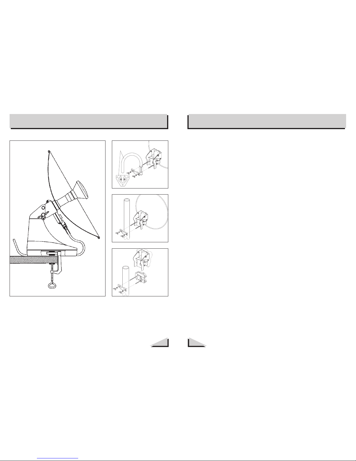
Elevation
Azimut
LNB-
Halter
Bild 3
Detail: Flügelschraube und Elevationsgradskala
5. Polarisationsentkopplung
Je nach Standort muß zur Bildoptimie-
rung der LNB, wie in Bild 4 gezeigt,
verdreht werden. Dadurch wird die opti-
male Polarisationsentkopplung einge-
stellt.
Achten Sie bei dieser Einstellung darauf,
daß Sie den Standfuß der Antenne nicht
mehr verschieben.
Vergewissern Sie sich jetzt , daß Sie den gewünschten Satelliten
empfangen, indem Sie am Receiver andere Programme einschalten.
Bild 4

Befestigungsmöglichkeiten
7
Technische Daten
8
Die Multimo basiert auf dem sogenannten Cassegrain-Prinzip, das
hauptsächlich im professionellen Bereich eingesetzt wird.
Vorteile der MULTIMO gegenüber Offset-Antennen:
• kein weit ausladender Tragarm für den LNB, somit kompakter
• hoher Flächenwirkungsgrad
• LNB befindet sich im Schatten des Parabolspiegels
und ist keiner Sonneneinstrahlung ausgesetzt (Lebensdauer)
• kleinerer Öffnungswinkel als bei Offset-Antennen gleicher
Größe (weniger Störungen)
Teileliste:
• 1 Parabolantenne komplett mit LNB und Halterung
• 1 Kunststoff-Standfuß mit Abdeckkappe
• 10 m SAT-Koaxialkabel mit F-Steckern und Tülle
• 1 Schraubzwinge zur Befestigung des Standfußes
• 1 Bedienungsanleitung mit Garantieschein
• 1 Mastschelle
Receiver:
Für den Empfang der analogen Programme können herkömmliche
Analog-Receiver eingesetzt werde, die einen Eingangs-frequenzbereich
von 950 ... 2150 MHz haben. Wir empfehlen Receiver von ZEHNDER,
die eine besonders niedrige FM-Schwelle besitzen und somit sehr
leistungsstark sind.
Für den Empfang von digitalen Programmen empfehlen wir einen Digit
alsatellitenreceiver ebenfalls aus dem ZEHNDER Programm.
Antennen-Mast
Befestigung am
Antennen-Mast
Antennen-Mast
Befestigung der
Quick-in Halterung
am Antennen-Mast
Befestigung mit der
Schraubzwinge
Befestigung mit
dem Wandhalter
Wandhalter

Technische Daten AX 40
10
9
Azimut
... ist der Winkel, der die Richtung angibt,
aus welcher der Satellit empfangen wird.
Beispiel: Der Satellit ASTRA befindet sich
im Azimut auf 19,2° Ost.
Elevation
... ist der Winkel, der die Erhebung der
Satelliten über dem Horizont angibt.
Polarisationsentkopplung
... ist ein Maß für die Beeinflussung
elektromagnetischer Wellen unterschied-
licher Polarisation (horizontal und ver-
tikal) nach ihrer Trennung durch die
Polarisationsweiche.
Die Angabe erfolgt in Dezibel (dB) und
läßt erkennen, in welchem Umfang die
nicht erwünschte Polarisation im Signal-
weg auftritt.
LNB
Unter LNB = Low Noice Blockconverter
versteht man die rauscharme Em-
pfangseinheit einer Satelliten-Antenne.
Der LNB setzt die Frequenzen in einen
niedrigeren Frequenzbereich um, damit
die Signale über ein Koaxialkabel
transportiert werden können.
Orbit
Orbit wird die geostationäre Umlauf-
bahn der Satelliten in 36.000 km über
dem Äquator genannt, auf der sich die
Satelliten für den Betrachter auf der Erde
immer an der gleichen Stelle befinden.
Die Gradangabe erfolgt stets bezogen
auf den Nullmeridian, wobei die ost-
wärtige Richtung als Zählrichtung gilt.
Spiegel:
Durchmesser:
Gewinn:
Material:
LNB:
Frequenzbereich:
Oszillator-Frequenz:
Schaltsignal:
Ausgangsfrequenz:
Rauschmaß:
Ausgangsimpedanz:
Fernspeisung:
Stromverbrauch:
40 cm
ca. 32 dB bei 11, 3 GHz
Aluminium ca.1.2 mm
Rand verstärkt
Low-Band High-Band
10,7 - 11,8 GHzt 11,8 - 12,75 GHz
9,75 GHz und 10,6 GHz
0 kHz 22 Khz
950 - 2150 MHz
ca. 0,6 dB typ.
75 Ohm
14V - vertikal / 18V - horizontal
ca. 140 mA
Die MULTIMO besitzt einen LNB mit 9,75 GHz und 10,6 GHz Oszillatorfrequenz,
der den neuesten technischen Stand aufweist. Der LNB ermöglicht den Empfang aller
Programme des ASTRA-Systems sowie anderer Satelliten z.B. EUTELSAT, HOTBIRD,
TÜRKSAT etc.
Bei der Kombination der MULTIMO mit anderen Receivern müssen die Empfangs-
frequenzen des Receivers aktualisiert werden, wenn sie nicht auf 9,75 GHz abgestimmt
sind..
Wir empfehlen sich an der Programmtabelle zu orientieren die der Be-
dienungsanleitung des Receivers beliegt:
1Receiver v. Zehnder, mit nie-
driger FM-Schwelle; (nicht abgebildet)
2Masthalterung (BN 101)
Wandhalterung (BN 100)
Fensterdurchführungskabel
(BN 102)
Quick-in Halterung (BN 103)
Änderung technischer Daten vorbehalten
3
4
5
SAT-Kabel 5,0 m lang mit mon-
tierten F-Steckern (BM 325-02)
6
Zubehör für MULTIMO AX 40
Programmtabelle
2
3
4
6
5
Begriffe:

Standort-Tabelle Deutschland Standort-Tabelle EUROPA
12
11
DEUTSCHLAND
Ort
Aachen
Augsburg
Bad Reichenhall
Bayreuth
Berlin
Bielfeld
Bonn
Braunschweig
Bremen
Bremerhaven
Chemnitz
Celle
Cottbus
Darmstadt
Dortmund
Dresden
Duisburg
Düsseldorf
Erfurt
Essen
Emden
Flensburg
Frankfurt/Main
Frankfurt/Oder
Freiburg
Fulda
Garmisch-Partenk.
Gera
Göttingen
Hagen
Halle/Saale
Hamburg
Hannover
Heide/Holstein
Heidelberg
Heilbronn
Hildesheim
Hof
Ingolstadt
Iserlohn
Kaiserslautern
Karlsruhe
Kassel
Kiel
Koblenz
Köln
Konstanz
Krefeld
Leipzig
Lingen
Lübeck
Magdeburg
Mainz
Mannheim
Marburg
Mönchengladbach
München
Münster
Neubrandenburg
Nürnberg
Oberstdorf
Oldenburg
Osnabrück
Ort
Paderborn
Passau
Potsdam
Recklinghausen
Regensburg
Rostock
Saarbrücken
Schweinfurt
Schwerin
Siegen
Stralsund
Stuttgart
Trier
Uelzen
Ulm
Weimar
Wilhelmshaven
Wolfsburg
Wuppertal
Würzburg
ASTRA
1A ...1D
19,2° Ost
EL AZ
EUTELSAT
II F-1,Hotbird
13° Ost
EL AZ
EUTELSAT
II F-1,Hotbird
13° Ost
EL AZ
ASTRA
1A...1D
19,2° Ost
EL AZ
30,6
33,6
34,9
32,3
29,7
29,7
30,8
29,7
28,6
28,1
31,2
29,3
31,4
32,0
30,0
31,1
30,0
30,2
31,0
30,0
28,1
26,9
31,7
30,3
33,8
31,4
34,9
32,3
W = West
O = Ost
EL = Elevation
AZ = Azimut W = West
O = Ost
EL = Elevation
AZ = Azimut
30,0
34,0
30,2
29,9
33,4
28,0
32,4
32,0
29,0
30,8
28,1
33,2
31,7
29,0
33,7
32,2
28,1
29,6
30,2
32,3
10,3
7,4
7,8
14,9
9,1
8,9
15,7
11,4
10,2
14,0
7,6
13,0
16,0
10,5
12,0
10,7
13,4
10,3
15,0
11,8
EUROPA
EUTELSAT
II F-1,Hotbird
13° Ost
EL AZ
Ort
Barcelona
Bern
Bordeaux
Bregenz
Brüssel
Budapest
Dublin
Genf
Göteborg
Helsinki
Kopenhagen
Linz
London
Madrid
Mailand
Marseille
Oslo
Paris
Perpignan
Prag
Salzburg
Stockholm
Warschau
Wien
Zürich
ASTRA
1A...1D
19,2° Ost
EL AZ
39
36
36
35
31
36
25
35
25
21
27
34
29
42
37
38
22
32
39
33
35
23
30
35
35
41
37
37
36
32
35
27
37
25
21
27
35
30
45
38
40
23
34
40
34
36
23
30
34
36
26
8
19
4
11
8 W
24
9
1
14 W
1
2 W
17
27
5
11
3
14
15
2 W
0
6 W
10 W
5 W
6
25
16
27
13
19
0
31
18
8
6 W
8
6
24
35
14
20
10
22
24
6
8
1
2 W
4
14
31,5
34,4
35,2
32,7
30,0
30,3
31,6
30,2
29,2
28,7
31,8
29,8
30,8
32,7
30,8
31,6
30,8
31,1
31,6
30,8
28,8
27,4
32,4
30,1
34,7
32,0
35,4
31,7
31,0
31,0
31,1
28,8
30,0
33,2
33,5
30,3
32,3
34,0
31,0
33,1
33,6
31,2
27,9
32,1
31,4
35,1
30,9
31,2
29,9
28,5
30,4
32,5
33,1
31,7
34,7
30,4
28,8
33,3
29,1
30,0
30,7
34,3
30,1
30,7
34,3
30,1
30,7
33,7
28,3
33,2
32,6
28,7
31,6
28,0
33,9
32,6
29,4
34,4
31,6
28,7
30,0
31,1
32,9
8,9 O
2,8 O
0,2 O
1,8 O
0,2
W
5,6 O
7,6 O
3,1 O
5,2 O
5,5 O
0,2 O
3,6 O
1,6
W
5,6 O
7,0 O
0,9
W
7,9 O
7,9 O
2,5 O
7,6 O
7,2 O
4,3 O
5,6 O
1,9
W
6,9 O
4,3 O
2,5 O
1,1 O
3,9 O
7,0 O
1,2 O
3,7 O
4,1 O
5,6 O
5,0 O
3,8 O
1,3 O
2,0 O
6,7 O
6,8 O
6,0 O
4,4 O
3,5 O
7,0 O
7,7 O
5,1 O
8,2 O
4,6 O
7,1 O
2,8 O
1,7 O
6,1 O
5,9 O
5,5 O
1,9 O
6,8 O
0,2
W
2,5 O
5,4 O
0,5
W
0,2
W
7,4 O
1,1 O
1,0 O
7,9 O
3,6 O
1,9 O
6,4 O
0,2
W
5,0 O
8,3 O
3,0 O
4,0 O
2,1 O
6,0 O

Gewährleistung
14
13
Für die MULTIMO übernimmt die Firma HEINRICH ZEHNDER GmbH
in Tennenbronn die Gewährleistung für verwendete Materialien und
Verarbeitung für eine Frist von 24 Monaten ab Verkaufsdatum.
Bei auftretenden Produktfehlern während der Gewährleistungszeit
wird die Antenne ohne Kosten für Arbeitszeit und Materialaufwand
in Abhängigkeit von folgenden Bedingungen wieder in einen
funktionstüchtigen Zustand versetzt.
Bedingungen:
Die auftretenden Funktionsstörungen müssen nachweislich auf
fehlerhaften Materialien und Fabrikationsfehlern beruhen.
Die Gewährleisstung ist nur gültig, wenn die Gewährleisstungkarte
(siehe letzte Seite) ordnungsgemäß und vollständig ausgefüllt ist.
Modelltyp, Händler- und Kundenadresse sowie das Verkaufsdatum
müssen vorliegen. Der Kaufzeitpunkt ist durch Kassenzettel, Rechnung,
Quittung oder andere gültige Kaufbestätigungen nachzuweisen.
ZEHNDER behält sich vor, nach eigener Wahl mangelhafte Teile zu
ersetzen oder nachzubessern.
Für alle Gewährleisstungsfälle ist der Fachhändler, bei dem der
Käufer die Antenne gekauft hat, als Vertragspartner zuständig.
•
•
•
•
Diese Gewährleisstung ist nicht anwendbar für Defekte, die nicht
auf Material- oder Verarbeitungsfehler zurückzuführen sind. Von der
Gewährleisstung sind im einzelnen ausgeschlossen:
Für ausgeführte Leistungen von Werkstätten oder Fachhändlern, die
nicht von ZEHNDER beauftragt sind, trägt ZEHNDER nicht die Kosten
und übernimmt nicht das Risiko für eventuell entstandene Schäden.
Regelmäßige Überprüfungen, Justierungen und Umstellungen sind nicht
in der Gewährleisstung eingeschlossen.
ZEHNDER behält sich das Recht vor, Designänderungen sowie Ver-
besserungen vorzunehmen, ohne sich zu verpflichten, bereits herge-
stellte Produkte zu modifizieren.
• Bedienungsfehler
• Unfallschäden
• fahrlässige Behandlung
• Modifikationen
• ungeeignete Installation oder Verpackung
• Schäden verursacht durch Blitz, Wasser oder Feuer
• andere Ursachen, die von ZEHNDER nicht kontrollierbar sind

16
15
Preface Safety notes
With buying the MULTIMO you settled on an efficient, compact
antenna. The MULTIMO was especially developed for the television
reception of the ASTRA satellites in mobile use. But it is also suitable to
receive programmes of the HOTBIRD, Telecom, Hispasat and satellites
within the strong signal footprints.
MULTIMO is a pure one-partner antenna for the reception of the
vertical and horizontal polarized signals in the frequency range 10.7
GHz - 12.75 GHz.
MULTIMO offers you a number of applications together with the
offered accessories:
The following chapters shall facilitate the installation and orientation of
your MULTIMO. In order to receive an optimum reception you should
orientate the MULTIMO system as described below:
Safety notes
Location
Elevation angle
Tuning the TV-set
Fine adjustment
Cross polarisation
Mounting possibilities
Tecnical data
Location list
Garantee
We wish you great fun and a good reception.
Please treat with care! MULTIMO is a high-precision product and must
not be bent or damaged. This would affect the very good technical data
and receiving characteristics.
Safety notes for installation:
If you mount your MULTIMO onto a balustrade by means of the screw
clamp you have to check the correct position of the base from time to
time.
We do not accept any liability for damages due to an insufficient fixing.
In case of stormy weather we recommend to remove the antenna from
the base and to mount it safely by means of the mast mounting and
wall mounting.
(see chapter „Mounting possibilities“).
High voltage and lightning protection:
In case of mounting under the roof or at the window grounding is not
necessary if the highest point of the MULTIMO is at least 2 m beneath
the gutter and the farthest point is not more than 1.5 m away from the
outer wall.
In case of roof mounting the antenna mast has to be connected to
ground. Information concerning the correct grounding can be found
in the VDE standards as well as in the general lightning protection
regulations.
Please contact your specialized dealer.
GB

Azimuth angle
Elevation
angle
Tv-set SAT-receiver Illustration 2
Location and Orientation
18
17
The MULTIMO is completely mounted. So you do not have to struggle
with mounting instructions and you do not need any tools.
The following illustrations show you how to proceed when installing
and orienting the MULTIMO .
The location table will help you to adjust the elevation and the
azimuth. In this table you will find the values for the respective
location.
Example: Location near London for ASTRA reception
Elevation 29 ° -- Azimuth 24°
1. Location
The MULTIMO needs a location with a free view to the south.
Houses, high trees etc.may not impede the view to the satellite.
Remember that the cable has a length of 10 m. The MULTIMO has to
be placed on an even surface ( illustration 1).
If the MULTIMO is not placed
to an even surface the elevation
indicated or the declination of
the LNB (illustration 4) is not
correct. Then these adjust-ments
have to be corrected later in
oder to get best reception.. South
ASTRA
1A / 1B
/ 1C
Illustration 1
2. Elevation angle
The elevation angle is pre-set to 30°. This facilitates the discovery of the
satellite ASTRA if you are in Germany. In southern and northern regions
you should adjust the elevation angle for your respective position. You
will find these specifications in the location table.
3. Tuning of the TV channel
Generaly we recomend the use of Scart cabel to interconnect receiver
and TV-set. In this cas the following procedure can be avoided!
After having found a place for your MULTIMO you have to connect the
LNB of the antenna with your receiver by using the satellite cable.
The cable is equipped with F-plugs which must
be connected to the respective sockets.
The F-plug with the bush hase to be connected with the LNB.
Now connect your TV-set to the SAT-receiver and switch the sets on.
Please pay attention to the notes in the operation manual of the SAT-
receiver. (Attend to illustration 2).
The SAT-receiver must be ajusted to a reception channel which has
the frequency of the desired satellite and programm. Then follows the
ajustments of elevation and azimuth.
4. Fine adjustment
When adjusting the MULTIMO, place yourself behind or beside the it
so that you will not screen the satellite signals by your body. First turn
the MULTIMO in the azimuth. If you have a compass at hand it will be
easier to orientate MULTIMO. But it is also possible to do this by using

Mounting possibilities
20
19
But it is also possible without a
compass; see illustration 3:
Orientate your MULTIMO to the
south.
Slowly turn the it to the left
eastward until a picture appears
on the TV-set.
Move the whole antenna a little
bit to the left and to the right in
order to optimize the quality of the
picture.
Now release the thumb screw
of the elevation adjustment and
slightly move the LNB fixing
upward and downward to further
optimize the quality of the picture.
Please do not perform the adjustment at the dish reflector but at the
LNB fixing so that the reflector will not be damaged. Later retighten the
thumb screw.
Elevation
Azimuth
LNB-
fixing
Illustration 3
Detail: Thumb screw and elevation scale
5. Cross polarization
According to the location the LNB can be
turned for the optimization of the picture
as shown on illustration 4. By this the
optimum decoupling of the polarization
will be set.
When performing this setting take care
that the base of the MULTIMO will not be
moved.
Now make sure that you receive the desired satellite by switching on the
corresponding programmes at the receiver.
Illustration 4
Antenna mast
Mounting at the
antenna mast
Antenna mast
Fastening of the
Quick-in mounting
at the antenna mast
Mounting with the
screw clamp
Fixing by the wall
mounting
Wall mount

Technical data Technical data AX 40
22
21
This antenna is based on the so-called Cassegrain-principle, that is
successfully used for a long time in professional ranges (e.g. directional
radio links).
Advantages of MULTIMO compared with usual offset-antennas:
• no long feed carrier for the LNB and therefore more compact
• higher efficiency in aperture and area
• the LNB for MULTIMO is located in the shadow of the
parabolic dish and therefore not exposed to sun rays
(long life of the LNB)
• MULTIMO has a smaller beam than offset-antenna of same
size (lower receiving interferences)
Part list
• Parabolic antenna completely with LNB and fixing
• Base with cover
• Satellite coaxial cable 10 m with F-plugs and rubber bush
• 1 Screw clamp for the fixing of the base
• 1 Operating Manual with guarantee certificate
Receiver:
In connection with the MULTIMO each conventional receiver with a
connection for a voltage-controlled LNB can be used.
We recommend ZEHNDER-Stereo-SAT-Receivers with low FM-threshold
in order to get high performance reception.
Terms
Azimuth
... is the angle, indicating the direc-
tion from which the satellite is received.
Example: The satellite ASTRA is in the
Azimuth on 19.2° East.
Elevation
... is the angle, indicating the elevation of
the satellites over the horizon.
Cross polarization
... is a measure for the strength between
electromagnetic fields of different
polarization (e.g. horizontal and vertical)
after separation by a polarization filter.
The indication is in decibel (dB) and
shows how the other polarization can
influence the polarization wanted.
LNB
LNB = Low Noise Block Converter is a
low noise receiving and converting unit
of a satellite receiving system.
The LNB converts the frequencies into
a lower frequency range so that the
signals can be easily conducted via a
coaxial cable.
Orbit
Orbit means the geostationary ring of
the satellites in 36.000 km over the
equator, which is always at the same
point in the sky for the viewer on the
earth.
The indication of degrees is referred to
the zero meridian where the eastward
direction is the counting direction.
Dish
Diameter:
Gain:
Material:
LNB
Frequency range:
Oscillator frequency:
IF frequency:
Noise figure:
Output impedance:
Remote power:
Current consumption:
40 cm
approx. 32 dB at 11.3 GHz
aluminium, 1,2 mm,
with strengthened edge
Low-Band High-Bnad
10.7-11,8 GHz 11,8- 12.75
GHz
9.75 GHz and 10,6 GHz
0 KHz 22 KHz
950 - 2150 MHz
0.6 dB typical
75 Ohm
14V - vertical / 18V - horizontal
We reserve the right to modify the technical data
without previous advise.

European Cities
EUTELSAT
II F-1,Hotbird
13° East
EL AZ
Location
Barcelona
Bern
Bordeaux
Bregenz
Brüssel
Budapest
Dublin
Genf
Göteborg
Helsinki
Kopenhagen
Linz
London
Madrid
Mailand
Marseille
Oslo
Paris
Perpignan
Prag
Salzburg
Stockholm
Warschau
Wien
Zürich
ASTRA
1A...1D
19,2° East
EL AZ
39
36
36
35
31
36
25
35
25
21
27
34
29
42
37
38
22
32
39
33
35
23
30
35
35
41
37
37
36
32
35
27
37
25
21
27
35
30
45
38
40
23
34
40
34
36
23
30
34
36
26
8
19
4
11
8 W
24
9
1
14 W
1
2 W
17
27
5
11
3
14
15
2 W
0
6 W
10 W
5 W
6
W = West
O = East
EL = Elevation
AZ = Azimuth
25
16
27
13
19
0
31
18
8
6 W
8
6
24
35
14
20
10
22
24
6
8
1
2 W
4
14
24
23
Location list EUROPE
The MULTIMO uses a LNB with 9.75 GHz and 10.6 GHz oscillator frequency. This is
up to date. This LNB enables you to receive all programmes of the ASTRA system such
as other satellites EUTELSAT, HOTBIRD, TÜRKSAT etc..
When combining the MULTIMO with other receivers the receiving frequencies of the
receiver may be updated.
We recommend to have a look on the program list of the receiver and its user
manual.
Program list
Further accessories for MULTIMO:
1Receiver with low threshold
ZEHNDER ( not shown)
2Mast mounting (BN 101)
Wall mounting (BN 100)
Cable leading through window
(BN 102)
Quick-in mounting (BN 103)
3
4
5
Satellite coaxial cable 5.0 m long
with mounted F-plugs (BM 325-02)
6
2
3
4
6
5

Location list Germany Warranty
26
25
Germany
Location
Aachen
Augsburg
Bad Reichenhall
Bayreuth
Berlin
Bielfeld
Bonn
Braunschweig
Bremen
Bremerhaven
Chemnitz
Celle
Cottbus
Darmstadt
Dortmund
Dresden
Duisburg
Düsseldorf
Erfurt
Essen
Emden
Flensburg
Frankfurt/Main
Frankfurt/Oder
Freiburg
Fulda
Garmisch-Partenk.
Gera
Göttingen
Hagen
Halle/Saale
Hamburg
Hannover
Heide/Holstein
Heidelberg
Heilbronn
Hildesheim
Hof
Ingolstadt
Iserlohn
Kaiserslautern
Karlsruhe
Kassel
Kiel
Koblenz
Köln
Konstanz
Krefeld
Leipzig
Lingen
Lübeck
Magdeburg
Mainz
Mannheim
Marburg
Mönchengladbach
München
Münster
Neubrandenburg
Nürnberg
Oberstdorf
Oldenburg
Osnabrück
Location
Paderborn
Passau
Potsdam
Recklinghausen
Regensburg
Rostock
Saarbrücken
Schweinfurt
Schwerin
Siegen
Stralsund
Stuttgart
Trier
Uelzen
Ulm
Weimar
Wilhelmshaven
Wolfsburg
Wuppertal
Würzburg
ASTRA
1A...1D
19,2° East
EL AZ
EUTELSAT
II F-1,Hotbird
13° East
EL AZ
EUTELSAT
II F-1
13° East
EL AZ
ASTRA
1A / 1B / 1C
19,2° East
EL AZ
30,6
33,6
34,9
32,3
29,7
29,7
30,8
29,7
28,6
28,1
31,2
29,3
31,4
32,0
30,0
31,1
30,0
30,2
31,0
30,0
28,1
26,9
31,7
30,3
33,8
31,4
34,9
32,3
W = West
O = East
EL = Elevation
AZ = Azimuth
30,0
34,0
30,2
29,9
33,4
28,0
32,4
32,0
29,0
30,8
28,1
33,2
31,7
29,0
33,7
32,2
28,1
29,6
30,2
32,3
10,3
7,4
7,8
14,9
9,1
8,9
15,7
11,4
10,2
14,0
7,6
13,0
16,0
10,5
12,0
10,7
13,4
10,3
15,0
11,8
31,5
34,4
35,2
32,7
30,0
30,3
31,6
30,2
29,2
28,7
31,8
29,8
30,8
32,7
30,8
31,6
30,8
31,1
31,6
30,8
28,8
27,4
32,4
30,1
34,7
32,0
35,4
31,7
31,0
31,0
31,1
28,8
30,0
33,2
33,5
30,3
32,3
34,0
31,0
33,1
33,6
31,2
27,9
32,1
31,4
35,1
30,9
31,2
29,9
28,5
30,4
32,5
33,1
31,7
34,7
30,4
28,8
33,3
29,1
30,0
30,7
34,3
30,1
30,7
34,3
30,1
30,7
33,7
28,3
33,2
32,6
28,7
31,6
28,0
33,9
32,6
29,4
34,4
31,6
28,7
30,0
31,1
32,9
8,9 O
2,8 O
0,2 O
1,8 O
0,2
W
5,6 O
7,6 O
3,1 O
5,2 O
5,5 O
0,2 O
3,6 O
1,6
W
5,6 O
7,0 O
0,9
W
7,9 O
7,9 O
2,5 O
7,6 O
7,2 O
4,3 O
5,6 O
1,9
W
6,9 O
4,3 O
2,5 O
1,1 O
3,9 O
7,0 O
1,2 O
3,7 O
4,1 O
5,6 O
5,0 O
3,8 O
1,3 O
2,0 O
6,7 O
6,8 O
6,0 O
4,4 O
3,5 O
7,0 O
7,7 O
5,1 O
8,2 O
4,6 O
7,1 O
2,8 O
1,7 O
6,1 O
5,9 O
5,5 O
1,9 O
6,8 O
0,2
W
2,5 O
5,4 O
0,5
W
0,2
W
7,4 O
1,1 O
1,0 O
7,9 O
3,6 O
1,9 O
6,4 O
0,2
W
5,0 O
8,3 O
3,0 O
4,0 O
2,1 O
6,0 O
HEINRICH ZEHNDER GmbH, Tennenbronn, guarantees for used
material and processing of MULTIMO during a period of 24 months
beginning with the date of sale.
In case that product faults occur during the period of warranty the
antenna will be placed in functional condition without costs for working
time and expenditures for materials and supplies.
The following conditions have to be met:
Conditions:
The occurring malfunctions must be due to defective material and
fabrication faults.
The warranty is only valid if the waranty certificate is filled in correctly.
Type of the model, address of the dealer and the customer as well as
the date of sale must be given. The date of sale has to be proved by
sales slip, invoice, receipt or another valid purchase confirmation.
ZEHNDER reserves the right to replace or retouch faulty parts
according to own option.
For all warranty payments please contact the specialized dealer by
which you purchased the product.
•
•
•
•

28
27
This warranty is not applicable to defects which are not due to material
or processing faults. The following is excluded by the warranty:
For work done by workshops or specialized dealers not authorized by
us, ZEHNDER will not bear the costs and do not assume the risk for
possibly occurred damages.
Regular tests, adjustments and changes are not included in the
warranty.
ZEHNDER reserves the right to modify the design as well as to make
improvements without the obligation to modified products already
produced.
• Operating error
• Damage resulting from an accident
• Negligent treatment
• Modifications
• Unsuitable installation or packing
• Damages due to lightning, water or fire
• other causes which can not be checked by ZEHNDER


Gewährleistungskarte
Warranty certificate
Certificat de garantie
HEINRICH ZEHNDER GMBH
ANTENNEN-FUNKBAUTEILE
D-78144 Tennenbronn Germany
Weierhalde 37a
Tel.: 07729 8810 FAX: 07729 88172
http://www.zehnder-sat.de
(Bitte vollständig ausfüllen / Please fill-in completely / prière remplir complètement)
Bei Gewährleistungsansprüchen zusammen mit dem Gerät dem Fachhändler vorlegen.
In case of claims under warranty please present this certificate to the dealer together with the unit.
Au cas de demande de garantie il faudra soumettre ce certificat ensemble avec l‘antenne au marchand
spécialisé.
Fachhändler /
Specialized
dealer /
Marchand spécialisé:
Käufer /
Buyer /
Acheteur:
Kaufdatum /
Date of sale /
Date de l‘achat:
Ort / Place / Lieu:
Fachhändler /
Specialized dealer /
Marchand spécialisé:
Firma / Firm / Etablissements
Straße / Hausnummer Postleitzahl / Ort
Street / Number Postal code / Place
Rue / No. de la maison No. de zone postale / Lieu
Name; Vorname / Name; First name / Nom; Prénom
Straße / Hausnummer Postleitzahl / Ort
Street / Number Postal code / Place
Rue / No. de la maison No. de zone postale / Lieu
Datum / Date / Date:
Käufer / Buyer / Acheteur:
32 8 553
Table of contents
Languages:
Other Zehnder Rittling Antenna manuals