Zehnder Rittling AA 05 User manual

1
AA 05
Digital DVB-T Zimmerantenne
Die aktive Zimmerantenne AA 05 wurde
speziell zum Empfang von digitalen
terrestrischen TV- und Radio-Programmen
(DVB-T, DAB) im
VHF-/UHF-Empfangsbereich für den
Innenbereich (mit ausreichendem
Signalpegel) entwickelt.
Das flache platzsparende Design im
Silber-Metallic-Look passt sich ideal zu
aktuellen Fernsehgeräten und in moderne
Zimmereinrichtungen ein.
Merkmale
Aktive Antenne mit Verstärker
Variabel für horizontale, vertikale Aufstellung oder für die Wandmontage
Kompletter VHF/UHF-Breitband-Empfangsfrequenzbereich 47 – 860 MHz
(Kanal 02 bis 69)
geringes Rauschmaß, dank hochwertiger Schaltungstechnik
Schutzfilter gegen GSM-Störungen
Zwei-Wege-Stromversorgung, wählbar zwischen mitgeliefertem ext.
Steckernetzteil oder per Fernspeisung vom DVB-T Receiver
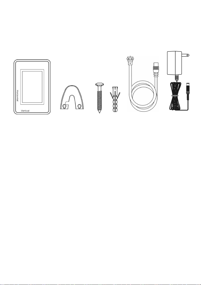
Lieferumfang
Antenne AA 05
Stützfuß zum Aufstellen
oder Aufhängen
Schrauben zur Wandbefestigung
2m Koax-Antennen-Anschlußkabel F-Stecker auf DIN-Stecker
Steckernetzteil 12V DC/250mA

2
Aufstellungshinweise
Betreiben Sie das Gerät nur in trockenen Innenräumen.
Am besten sind Räume mit Fenstern nach Außen, die somit bessere
Empfangsbedingungen für einen ausreichenden Signalpegel haben.
Setzen Sie das Gerät nicht über längeren Zeitraum direkter
Sonneneinstrahlung aus, da sich Materialveränderungen ergeben können.
Stellen Sie die Antenne nicht in die Nähe von Heizungen oder offenem Feuer
(z.B. Kerze): Brandgefahr!
Das Gerät sollte auf einem sicheren, festen Untergrund aufgestellt werden.
Der Standort darf nicht in Räumen mit hoher Luftfeuchtigkeit gewählt
werden, da Kondenswasserniederschläge zu Fehlfunktionen oder
Beschädigungen führen.
Vermeiden Sie den Kontakt des Gerätes mit Wasser, Flüssigkeiten oder
Feuchtigkeit. Nehmen Sie das Gerät nicht in der Nähe von Badewannen
oder Swimmingpools in Betrieb.
Reinigung
Ziehen Sie den Netzstecker, bevor Sie das Gerät reinigen. Benutzen Sie zur
Reinigung ein trockenes oder leicht angefeuchtetes Tuch.
Antenne Standfuß Wandbefestigung Koaxial Kabel Steckernetzteil

3
Betriebshinweise
In Gebieten mit geringen oder zu starken Empfangsfeldstärken ist ein
störungsfreier Empfang nicht in allen Fällen gewährleistet. Bei zu
schwachem Signalpegel sollte eine Richtantenne außerhalb des Gebäudes
verwendet werden.
In unmittelbarer Nähe zum Sender kann der Empfang durch zu hohe
Empfangspegel beeinträchtigt werden. Dann sollte eine fensternahe
Aufstellung vermieden werden.
Der Rundfunkempfang in Innenräumen kann zudem durch weitere Faktoren
beeinträchtigt werden:
- Räume in Stahlbetonbauten
- Räume mit metallbedampften Fenstern
- in unmittelbarer Nähe von sendenden elektr. Geräten (z.B. Mobiltelefonen)
Inbetriebnahme (siehe Anschlussskizze nebenan)
Schritt 1: Verbinden Sie die Antenne über das mitgelieferte Antennenkabel mit
dem DVB-T Receiver.
Achtung! Nicht an einen Sat-Receiver anschließen!
Schritt 2: Verbinden Sie das mitgelieferte Steckernetzteil mit der Antennenbuchse
auf der Geräterückseite und stecken Sie es anschließend in die 230V
Wandsteckdose.
Hinweis: Wenn Ihr DVB-T Receiver über eine
5-Volt-Fernspeisemöglichkeit über den Antenneneingang verfügt
(z.B. Zehnder DVB-T-Box), dann benötigen Sie Schritt 3 und somit
das Steckernetzteil nicht
Schritt 3: Stecken Sie den Stützfuß in das auf der Geräterückseite vorgesehene
Loch. Je nach Aufstellungsposition (vertikal oder horizontal) sollte zuvor
die Einsteckvorrichtung am Gehäuse gedreht werden.
Schritt 4: Verbinden Sie den Receiver mit dem TV-Gerät (siehe
Receiver-Handbuch) und schalten Sie beide Geräte ein.
Hinweis: Bei Verwendung des Receivers mit 5V-Fernspeisung
(siehe unter 3.) müssen Sie über das Einstellmenü des Receivers
sicherstellen, dass die 5V Stromversorgung der Antenne über das
Antennenkabel eingeschaltet ist (siehe Receiver-Handbuch).
4
Tipps zur Ausrichtung der Antenne
Zur Beurteilung der Empfangsqualität kann sowohl das
Fernsehbild, als auch die Signalpegel-/qualitätsanzeige im
Einstellmenü des Receivers herangezogen werden.
Sollte der Empfang gestört sein, drehen Sie die Antenne
leicht oder wechseln Sie durch seitliches Kippen
(horizontal – vertikal) die Polarisationsausrichtung und
kontrollieren Sie die Empfangsqualität.
Sollte kein optimaler Empfang möglich sein, stellen Sie die
Antenne an einem anderen Ort auf (Empfehlung:
Fensternähe) und wiederholen Sie die Prozedur.
Auch bei einer Installation an der Wand sollte zuvor durch Verändern der
Position an der Wand oder im Raum die Empfangsqualität überprüft werden.
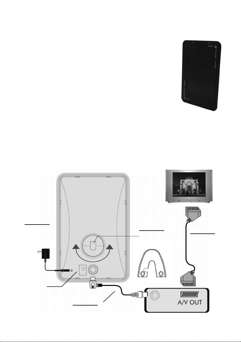
Anschlüsse:
AA 05 Rückseite
Schritt 1:
Antennenkabel 5V/40mA
Schritt 4:
SCART-
KABEL
TV
Schritt 3:
Stützfuß
DVB-T Receiver
Schritt 2:
230V
Steckdose
9-12V DC
Versorgungsanschluss
5
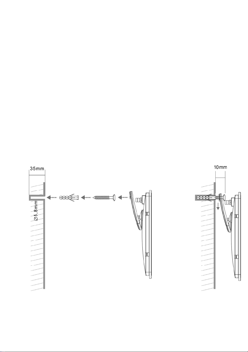
Wandmontage (siehe Skizze)
1. Nach Herausfinden der günstigsten Stelle an der Wand markieren Sie mit
einem Bleistift die 2 Positionen der zu bohrenden Schraubenlöcher zur
Befestigung des Standfußes.
2. Bohren Sie mit einem 5,8mm-Bohrer die zwei Löcher auf eine Tiefe von
ungefähr 35mm in die Wand. (Bei Befestigung auf einem Holzuntergrund
benötigen Sie keine Bohrungen und Dübel)
3. Schlagen Sie mit einem Hammer die beiden Dübel in die Bohrungen ein.
4. Drehen Sie die Schrauben mit Hilfe eines Schraubendrehers nur soweit in
die Bohrungen hinein, damit Sie den Standfuß noch bequem einhängen
können. Lassen Sie die Schrauben ca. 10mm von der Wand herausstehen.
5. Verbinden Sie die Kabel mit der Antenne und hängen sie mit dem Standfuß
an den zwei Schrauben ein.

6
Technische Daten:
Frequenzbereich VHF 47~230MHz, Kanal 02~12
UHF 470~860MHz, Kanal 21~69
Verstärkung 21 ±3 dB
Stromversorgung 1.
oder
2.
230V AC/100mA, mit Netzteil,<0,9W
5V DC/40mA, von Receiver, <0,2W
Steckernetzteil
Verbrauch
AC ~230V/50Hz; DC 12V/250mA
<0,4W (Nullast), <0,9W (Betrieb)
Gewicht ~210 g
Größe: B x H x T (mm) 139 x 209 x 23
HEINRICH ZEHNDER GMBH Telefon: 07729/881-0
Weierhalden 37/1 FAX: 07729/881-72
http://www.zehnder-sat.de
Dieses Produkt ist mit einer Energiesparschaltung nach
der EU Verordnung 278/2009 für externe Netzteile und
nach der Richtlinie 2005/32/EG zur umweltgerechten
Gestaltung energiebetriebener Produkte ausgestattet
(Ökodesign-Anforderungen).
Entsorgung
Elektronische Geräte gehören nicht in den Hausmüll, sondern
müssen gemäß der RICHTLINIE 2002/96/EG DES EURO-
PÄISCHEN PARLAMENTS UND DES RATES vom 27. Januar
2003 über Elektro- und Elektronik-Altgeräte fachgerecht entsorgt werden.
„Bitte geben Sie dieses Gerät am Ende seiner Verwendung zur Entsorgung
an den dafür vorgesehenen öffentlichen Sammelstellen ab."

7
AA 05
Digital Indoor Antenna
AA 05 was specially designed to receive
digital terrestrial TV signal as well as radio
programs (DVB-T, DAB) in the VHF- and UHF-
frequency range at indoor use.
The metal-silver, flat and stylish housing is
a perfect match for your modern TV set and
your modern styling living room.
Features
Active antenna with embedded amplifier
Friendly Advanced design for either Horizontal or Vertical position
For Desktop or wall mounting installation
complete VHF/UHF wide band range reception 47-860 MHz (CH 02-69)
Low noise figure by using high-quality components
Built-in filter against GSM signal interference
Convenient Powering System – two ways selectable either with power adaptor
or with DVB-T receiver
Accessories attached :
1) Antenna AA 05
2) Foot for standing or wall mounting
3) Wall mounting kit
4) F-connector to IEC-connector antenna coaxial cable, 2m
5) Power adaptor 12VDC/250mA
8
Location and Installation Notes:
Operate the antenna only at dry indoor places.
Rooms with windows are the most suitable locations to get best reception
quality with sufficiently high signal level.
Do not subject it to direct sunlight for longer periods, because material can
change for the worse.
Do not place the antenna close to heaters or naked lights (e.g. candles).
There might be a danger of fire!
Place the antenna on a safe and firm ground.
Protect the device from moisture, drips and splashes.
Cleaning
Before cleaning, unplug the antenna from power and antenna cable.
Use only a soft and slightly moistened cloth to clean the casing.
Main Unit Standing Unit Wall Mounting Coaxial Cable AC Adaptor

9
Operation Notes:
In areas with low or too high reception-field strength, interference-free
reception is not always guaranteed. If the signal level is too low, a directional
antenna should be placed outside the building.
In the immediate vicinity of the transmitter, reception may be impaired by a
too high reception level. In this case, you should avoid setting up the antenna
near a window.
Indoor radio reception can also be impaired by other factors:
- rooms in reinforced concrete buildings
- rooms with vapour-plated windows
- in positions directly beside transmitting electronic devices (e.g. mobile
phones)
Installation (Please refer to illustration):
Step 1. Take the IEC cable attached, and then connect one end to the IEC port,
and the other end to your DVB-T receiver shown in illustration
Attention! Don´t connect to a Satellite-Receiver!
Step 2. Take the power adaptor attached and Insert the end of DC connector into
DC jack on the back of AA 05, and then plug in the A/C end.
***** If your DVB-T receiver (e.g. from Zehnder) supplies with 5 VDC from
IEC connector, then it is not necessary to use the power adaptor.
Step 3. Take the standing unit attached , and then plug into the hole shown in
illustration to keep it standing. Before, check the position of rotating hole
for either vertical or horizontal direction.
Step 4. Connect your receiver and your TV by Scart Cable (see receiver manual)
and switch them on.
***** If your DVB-T receiver supplies with 5 VDC, ensure in the set-up menu
of the receiver, that the power supply to the antenna via the coax cable
is switched on.
10
Tips for correct Antenna Adjustment
To verify the quality of reception, you can use either the TV
picture or the option of displaying the reception level and
signal quality in the set-up menu of your receiver.
If reception is subject to interference, turn the antenna
slightly, or alter the direction of polarisation by titling it
sideways (horizontal – vertical), and check the quality of
reception.
If it is impossible to get optimum reception, set the antenna
up in a different place (we recommend a position close to a
window), and repeat the steps described above.
Even for wall mounting installation, before you should check antenna position
at the wall and in the room for best possible reception quality.
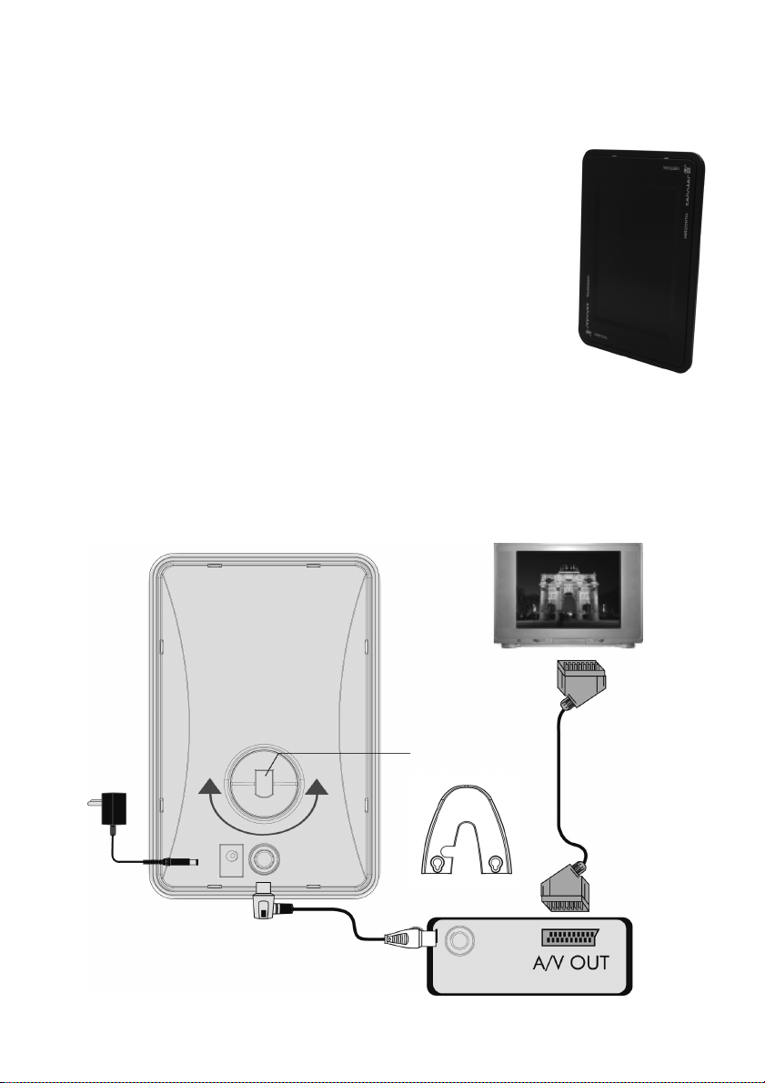
Connecting Illustration
AA 05 Rear View
Step 1.:
F to IEC RF Cable
Step 4. :
SCART
CABLE
TV
Step 3. :
Standing Unit
DVB-T Receiver Rear View
To AC
Outlet
Step 2. :
9-12V DC Power
Table of contents
Languages:
Other Zehnder Rittling Antenna manuals


Popular Antenna manuals by other brands

Alfa Network
Alfa Network APA-L01 Specifications

Naval
Naval PR-422CA Operation manual

Feig Electronic
Feig Electronic ID ISC.ANTH200/200 Series manual

TERK Technologies
TERK Technologies TV44 owner's manual

Directive Systems & Engineering
Directive Systems & Engineering DSE2324LYRMK quick start guide

HP
HP J8999A instructions


CommScope
CommScope CMAX-OMFX-43M-I53 Installation instruction

Ramsey Electronics
Ramsey Electronics DAP25 Kit assembly and instruction manual

COBHAM
COBHAM SAILOR 800 VSAT Replacement procedure

Trango Systems
Trango Systems AD900-9 Specification sheet

Steren
Steren ANT-100 user manual

IWCS
IWCS iriBelt II Quick start user guide