manuals.online logo
Brands
  1. Home
  2. •
  3. Brands
  4. •
  5. Winegard
  6. •
  7. Antenna
  8. •
  9. Winegard AS-2003 Operating instructions

Winegard AS-2003 Operating instructions

Other manuals for AS-2003

1

Other Winegard Antenna manuals

Winegard SK-1000 User manual

Winegard

Winegard SK-1000 User manual

Winegard WV750 User manual

Winegard

Winegard WV750 User manual

Winegard AIR 360+ User manual

Winegard

Winegard AIR 360+ User manual

Winegard RoadTrip Mission User manual

Winegard

Winegard RoadTrip Mission User manual
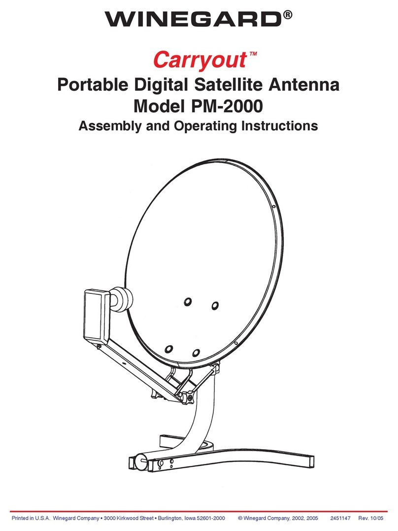
Winegard A3-2000 Operating instructions

Winegard

Winegard A3-2000 Operating instructions

Winegard Prostar 1000 PR-7010 User manual

Winegard

Winegard Prostar 1000 PR-7010 User manual

Winegard HD7080P User manual

Winegard

Winegard HD7080P User manual

Winegard HD7210P User manual

Winegard

Winegard HD7210P User manual

Winegard Freevision FV-HD30 User manual

Winegard

Winegard Freevision FV-HD30 User manual

Winegard Movin' View MV-4000 User manual

Winegard

Winegard Movin' View MV-4000 User manual

Winegard PR-8800 User manual

Winegard

Winegard PR-8800 User manual

Winegard MA1000W User manual

Winegard

Winegard MA1000W User manual

Winegard RZ-7500 User manual

Winegard

Winegard RZ-7500 User manual

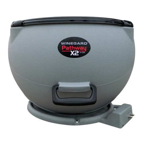
Winegard Pathway X2 Installation guide
Winegard

Winegard Pathway X2 Installation guide

Winegard HD7698P User manual

Winegard

Winegard HD7698P User manual

Winegard Movin' View MV3500A User manual

Winegard

Winegard Movin' View MV3500A User manual

Winegard HD-6000 User manual

Winegard

Winegard HD-6000 User manual

Winegard Movin' View MV3535A User manual

Winegard

Winegard Movin' View MV3535A User manual

Winegard HD7000R User manual

Winegard

Winegard HD7000R User manual

Winegard YA7000C User manual

Winegard

Winegard YA7000C User manual

Winegard Rayzar User manual

Winegard

Winegard Rayzar User manual

Winegard HD-8800 User manual

Winegard

Winegard HD-8800 User manual

Winegard HD-6010 User manual

Winegard

Winegard HD-6010 User manual

Winegard sensar series User manual

Winegard

Winegard sensar series User manual

Popular Antenna manuals by other brands

DAVIS Windex AV 3160 installation instructions

DAVIS

DAVIS Windex AV 3160 installation instructions

Belden Hirschmann BAT-ANT-N-14G-IP23 Mounting instruction

Belden

Belden Hirschmann BAT-ANT-N-14G-IP23 Mounting instruction

Vtronix YHK Fitting instructions

Vtronix

Vtronix YHK Fitting instructions

KVH Industries TracVision 6 Technical manual

KVH Industries

KVH Industries TracVision 6 Technical manual

Leica Geosystems GS10 user manual

Leica Geosystems

Leica Geosystems GS10 user manual

Sirio Antenne Gain-Master manual

Sirio Antenne

Sirio Antenne Gain-Master manual

Sony VCA-41 Installation/connections

Sony

Sony VCA-41 Installation/connections

ZCG Y100 Series installation guide

ZCG

ZCG Y100 Series installation guide

Advantech Wireless INTREPID120 Assembly instructions

Advantech Wireless

Advantech Wireless INTREPID120 Assembly instructions

Cerio ANT-10AO installation guide

Cerio

Cerio ANT-10AO installation guide

Alfa Network APA-L01 Specifications

Alfa Network

Alfa Network APA-L01 Specifications

Naval PR-422CA Operation manual

Naval

Naval PR-422CA Operation manual

Feig Electronic ID ISC.ANTH200/200 Series manual

Feig Electronic

Feig Electronic ID ISC.ANTH200/200 Series manual

TERK Technologies TV44 owner's manual

TERK Technologies

TERK Technologies TV44 owner's manual

TERK Technologies SIR3 owner's manual

TERK Technologies

TERK Technologies SIR3 owner's manual

Directive Systems & Engineering DSE2324LYRMK quick start guide

Directive Systems & Engineering

Directive Systems & Engineering DSE2324LYRMK quick start guide

HP J8999A instructions

HP

HP J8999A instructions

MobilSat MSP-S Mounting instructions

MobilSat

MobilSat MSP-S Mounting instructions

manuals.online logo
manuals.online logoBrands
  • About & Mission
  • Contact us
  • Privacy Policy
  • Terms and Conditions

Copyright 2025 Manuals.Online. All Rights Reserved.

1
Trouble Shooting for AS-2003 Satellite Antenna
®
2
I. Will not turn on
This trouble-shooting guide will help you solve problems with Model AS-2003 satellite antenna. If, after following these steps, you
need further assistance, call Winegard Technical Services at 1-800-788-4417.
Are you using a
power supply from
Winegard that
came with
the unit?
YES YES YES YES
Is the power
source plugged
into an active 120
VAC outlet?
Are you using a 13.8 VDC fil-
tered power source with at
least 3 amps of constant cur-
rent and no current limiting?
Replace power supply.
Is the power
source turned
on?
Measure the DC volt-
age between the
black (ground) and
brown wire at the pin
on the back of your
wall plate. See Figure
1. Does it measure
13+ VDC? 5
Remove the electron-
ics box lid. Find the
3-terminal connector
and the pins con-
nected to the red and
black (ground) wires.
Measure the DC volt-
age between these
pins. Does it measure
13+ VDC? Figure 2.
Now measure the
screw heads con-
nected to brown and
black wires on back
of control panel. Does
this measure 13+
VDC? Figure 1.
Does the power source
measure 13+ VDC?
Replace
connector YES
Replace
electronics
box.
Replace
power sup-
ply with 13.8
VDC filtered
power
source with
at least 3
amps of
constant
current and
no current
limiting.
Now measure the
screw heads con-
nected to the red and
black wires on the
3-terminal connector.
Does the voltage
measure 13+ VDC
between these screw
heads? Figure 2.
NO
NO
YES
NO
Replace
3-terminal
connector.
Replace
cable
containing
the power
wires.
YES
Figure 2
Figure 1
Pin connected
to red wire
Screw head
connected to
red wire
Pin connected
to black
(ground) wire
Screw head
connected to
black (ground) wire
YES
NO
YES
NO
NO
NO
Screw head
connected to red wire Screw head connected
to brown wire
Pin connected to
black (ground) wire
Pin connected to
brown wire
Screw head
connected to
black (ground)
wire
Pin connected
to red wire
Control panel inside RV
Electronics box on RV roof
3
YES
Replace
control panel.
Replace 9-terminal
connector.
Replace cable with
9 colored wires.
YES Replace connector
Measure the DC volt-
age between the
black (ground) and
red wires at the pin.
Does it measure 12.5
VDC?
Now measure the
screw heads con-
nected to red and
black wires on back
of control panel. Does
this measure 12.5
VDC also? Figure 1.
NO
NO
Remove the electron-
ics box lid. Find the
9-terminal connector
and the pins con-
nected to the red and
black (ground) wires.
Measure the DC volt-
age between these
pins. Does it measure
12.5 VDC? Figure 3.
NO
Now measure the
screw heads con-
nected to the red and
black wires on the
9-terminal connector.
Does the voltage
measure 12.5+ VDC
between these screw
heads? Figure 3.
NO
YES
Figure 3
Replace
electronics box
YES
Screw head connected to red wire
Pin connected to
black (ground) wire
Pin connected
to red wire
Screw head
connected to
black wire
Electronics box on roof
4
II. On, Park, Search & Off LEDs are on (No LNB power)
Is the receiver
plugged into an
active 120 VAC
outlet? Power on
receiver to verify.
YES
NO
Plug into receiver,
turn on and set
menu to signal
strength screen.
Is the bright white primary coax cable connected
from Satellite In jack on the back of the receiver to
the coax connection on the left side of the
electronics box? Figures 4 and 5.
NO
Connect the white
primary coax
cable correctly.
Figure 4 Figure 5
Coax cable connects from electronics
box to receiver.
Control panel inside RV
Wall Plate
Control Panel
inside vehicle
SEARCH/
MOVING
WINEGARD
ON OFF
PARK
AS-2003
SATELLITE SYSTEM
Do the lights
flush once?
then remain
ON?
YES
NO
Replace
electronics
box.
YES
5
Is LNBF coax
cable con-
nected from
the LNBF to
the coax posi-
tioned on the
right connec-
tor on the
electronics
box? Figures
6, 7.
Are all coax
connections
properly
crimped and
free of shorts?
YES YES
Does the
coax cable
connected to
the LNB mea-
sure 11-18
VDC between
the copper
center con-
ductor (+) and
connector (-)?
Figure 8.
Substitute
LNBF with an
LNBF known to
be good.
Power down,
then try to run
again. On the
control panel,
do all lights re-
main on?
Replace
connectors.
Replace receiver.
Does voltage
on Satellite In
receiver jack
measure be-
tween 12 & 18
volts?
See Note.
YES Replace coax
cable connecting
receiver and
LNBF.
NO
Connect
the LNBF
coax cable
correctly.
Connects from LNBF to
electronic box
Figure 6 Figure 7
YES
NO
NO
NO
YES
Replace elec-
tronics box.
NOTE
Do not try to insert the test meter probes into the
coax cable connectors. This will cause permanent
damage to the connectors. Use a short piece of
coax with a connector on one end, or Winegard’s
TE-1400 voltage tester (available from your
Winegard Distributor).
Figure 8
+ to coax
center conductor
- to coax
connector
The “Voltmeter”, com-
monly called a Multimeter,
can be purchased from
your local retailer.
6
Has the search
been selected
for 10 minutes or
more? See
Note. For the
initial search,
time could equal
10 minutes.
YES YES
Is the GPS an-
tenna mounted at
least 3 feet from
system and free
of obstructions?
Reposition GPS
antenna.
NO
Wait 10 minutes.
Remove lid on the elec-
tronics Box. Is GPS lead
connected correctly to
jumper cable in the
Electronic box? Fig. 9, 10
NO NO
Reconnect GPS
antenna lead.
III. Does not initiate Search routine
NOTE: If the vehicle
has gone 600 or more
miles since the last
use of the AS-2003,
GPS acquisition may
take longer. Also,
obstructions (buildings,
trees, hills, etc.) will
delay acquisition time.
Figure 9 Figure 10
YES
Reposition GPS
antenna and re-ini-
tiate Search routine.
Electronics box on RV roof Electronics box on RV roof
GPS antenna lead
7
Measure DC volt-
age between the
black and brown
(ground) wires at
the pin. Does it
measure 13
+VDC? Fig. 11.
Does the unit
run into an ob-
stacle while
attempting to el-
evate or rotate?
NO
Does the cable
restrict movement
while elevating or
rotating?
Adjust cables.
Remove obstacle.
Remove the
dish assembly
and turret. Are
there broken or
stripped gears?
Replace gears.
IV. On and Off LEDs are on (Motor stall error)
Replace connector.
Measure the screw
heads connected to
the brown and
black wires on the
back of the control
panel. Does it also
measure at least 13
VDC? Figure 11.
Does the power
source measure at
least 13 VDC?
Replace power
supply with a 13.8
VDC power source
with at least 3
amps of constant
current and no cur-
rent limiting.
NO YES
YES
YESYES
NO
NO
NO
YES
Remove lid to electronics box.
Identify the 3-terminal connector.
On connector, find pins connected
to the red and black (ground)
wires. Measure the DC voltage be-
tween these pins. Does it measure
at least 13 VDC? Fig. 12.
YES
YES
Measure the screw
heads connected to
the red and black
wires on the 3-termi-
nal connector. Does
the voltage measure
at least 13 VDC be-
tween these screw
heads? Figure 12.
NO
Figure 12
NO
Replace
electronics
box.
Replace cable
containg the
power wires.
YES
Replace
3-terminal
connector
Screw head
connects to
red wire
Screw head
connects to
black wire
Pin connected to
black (ground) wire
Pin connected to
red wire
Figure 11
Screw head connected
to brown wire
Screw head connected
to black wire
Pin connected to
black (ground) wire
Pin connected
to brown wire
Wall Plate
Control Panel
inside vehicle
SEARCH/
MOVING
WINEGARD
ON OFF
PARK
AS-2003
SATELLITE SYSTEM
Control panel inside RV
Electronics box on RV roof
8
V. On, Search and Off LEDs are on (Will not find signal)
Clear view of
SW sky
Any satellite within 20° longitude of the desired
satellite will be included as a required satellite
in the Search routine. To find 119, for example,
101, 110 and 119 are all required for a success-
ful Search routine.
Satellites 101, 110 and 119 are within 20° of each other Is the satellite
dish level,
within 3° with
horizon?
YES
NO
Try to level dish to
within 1° of horizon.
The unit will find the
signal with a 1° to
3° tilt, but search
time increases.
VI. Will not pass “Check Switch” function (DISH Network only)
Did you run Check
Switch within 6 minutes
after unit has acquired
satellite signal on
satellite 119?
YES YES NO
Did you
retest the
Check
Switch
function?
NO
Wait for unit to acquire
satellite signal on 119.
Run Check Switch again
within 6 minutes.
NO
Retest Check
Switch function.
Does the
dish move
while per-
forming the
Check
Switch?
Does the dish rotate almost a full
revolution while trying to locate
the second satellite during the
Check Switch function? Fig. 20.
NO
Connect LNBF correctly.
NO
Is the bright white pri-
mary coax connected
from the Satellite In jack
on the receiver back to
the coax connection of
the left side of the elec-
tronics box? Fig. 14, 15.
YES
NO
YES
Is the LNBF coax con-
nected from LNBF to
coax connection on the
right of electronics
box? Fig. 16, 17.
Connect
white
primary
coax
correctly.
YES
Move vehicle to
a different angle
so the stop is
not located be-
tween the two
satellites.
Connects from elec-
tronics box to LNBF.
Fig. 14
Connects
from elec-
tronics box
to receiver.
Fig. 15
Fig. 16 Fig. 17
61.5°
82°
92°
101°
110°
119°
148°
Figure 13
Wall Plate
Control Panel
inside vehicle
SEARCH/
MOVING
WINEGARD
ON OFF
PARK
AS-2003
SATELLITE SYSTEM
Does the unit run
into obstruction
or catch the wire
harness white
raising or rotat-
ing?
NO
YES
Remove
obstruction.
9
YES
On the connector on the
back of the control panel,
find the pins connected to
the purple and black
(ground) wires. Measure the
DC voltage between these
pins. Does it measure 4.8-
5.0 VDC? Figure 19.
Have you tried
changing transpon-
ders? 11 for DISH, 1
or 3 for DIRECTV, 11
for ExpressVu.
Change transponders.
Measure screw heads con-
nected to purple and black
wires on back of control
panel. Does it measure 4.8-
5.0 VDC? Figure 19.
For DISH, have
you cleared the
Check Switch,
started a new
search and run-
ning the Check
Switch again? For
DIRECTV, is the
receiver set to
“Two Sat. Oval
Dish”?
For DISH, retest
Check Switch
function; for
DIRECTV, set
receiver correctly.
Figure 18
Remove to
set switches
Is the primary (bright white) coax con-
nected to receiver that’s operating the
Check Switch routine? Fig. 21, 22.
NO
Operate Check Switch routine from
primary receiver.
YES
Are any devices inserted on the coax
between the satellite antenna and pri-
mary receiver?
YES
Remove device.
Fig. 21
Fig. 22
Fig. 20
t
Built-in stop (not visible)
119°
110°
t
t
Stop interrupts Check
Switch operation
Stop does not interrupt
Check Switch operation.
Built-in stop
(not visible)
119°
110°
t
Connects from electron-
ics box to PRIMARY
receiver.
NO
YES
Replace
electronics.
NO YES
Are the rotary
switches set to the
proper satellite?
Figure 18.
Replace
connector.
Set to 119 for DISH
Network, 101 for
DIRECTV and 092
for ExpressVu.
Switches will ap-
pear upside down
and numbers coun-
terclockwise.
NO
NO
YES
NO
Figure 19
Screw head
connected to
purple wire
Screw head
connected
to black wire
Pin connected
to black
(ground) wire
Pin connected
to purple wire
Control panel inside RV
10
VII. Unit will not park
Press Off button. Press
On button. Wait 5 sec-
onds for all LEDs to
flash. Press Park 1 time.
Does unit park?
Now measure the screw
heads connected to the
white and black wires
on the back of the con-
trol panel. Does this
measure 4.8-5.0 VDC?
Figure 23.
On the connector on
the back of the control
panel, find the pins
connected to the
white and black
(ground) wires. Mea-
sure the DC voltage
between these pins.
Does this measure
4.8-5.0 VDC? Fig. 23.
YES
NO
NO
NO
Replace electronics.
Are you using a 13.8
VDC filtered power
source with at least 3
amps of constant cur-
rent and no current
limiting?
YES Replace connector.
NO
Replace power supply.
Fig. 23
Screw head
connected to
white wire
Pin connected to
white wire
Screw head
connected to
black (ground) wire
Pin connected to
black (ground) wire
Control panel inside RV