Zen Float Tank User manual
ZEN FLOAT TANK TM
ASSEMBLY INSTRUCTIONS
VIDEO INSTRUCTIONS: https://www.youtube.com/zenfloatco
Version 2.5, updated 09/31/2020.
For help with watercare maintenance go to: zenfloatco.com/water-care/
1

IMPORTANT SAFETY INSTRUCTIONS &
WARNINGS
READ AND FOLLOW ALL INSTRUCTIONS.
When using this electrical equipment, basic safety precautions should
always be followed, including the following:
LOAD BEARING CAPACITY &
WATER
THE FLOAT TANK IS INTENDED FOR USE BY ONE
PERSON AT A TIME. CONFIRM THAT FLOOR LOAD
BEARING CAPACITIES ARE ABLE TO SUPPORT THE
FLOAT TANK WEIGHT WHEN FILLED AND
OCCUPIED. CALCULATE AT APPROXIMATELY 75 LBS (34 KG) PER
SQUARE FOOT WHICH IS BASED ON A HUMAN FLOATING IN THE
TANK THAT WEIGHS UP TO 300 LBS. TOTAL FLOAT TANK WEIGHT
WITH WATER AND SALT IS APPROXIMATELY 2200 LBS (998 KG).
TEMPERATURE
ALWAYS CHECK YOUR TEMPERATURE BEFORE
GETTING INTO THE FLOAT TANK. DO NOT EVER
FLOAT IF THE TEMPERATURE IS ABOVE 96º F (36º
C), OR IF IT FEELS ABNORMALLY WARM.
2

FIRE HAZARD
KEEP ALL FLAME AND OTHER HEAT SOURCES
AWAY FROM THE FLOAT TANK, INCLUDING THE
TANK FABRIC. THE FABRIC MAY BURN OR MELT
IF PLACED IN CONTACT WITH ANY FLAME OR
OTHER HEAT SOURCE.
DRUGS AND ALCOHOL USE
DO NOT USE DRUGS OR ALCOHOL BEFORE OR
DURING USE OF THE FLOAT TANK. THE USE OF
DRUGS OR ALCOHOL MAY INCREASE THE RISK
OF INJURY, UNCONSCIOUSNESS, AND POSSIBLE
DROWNING.
SLIPPING AND FALLING
TO AVOID FALLING OR OTHER INJURY, USE
CAUTION WHEN ENTERING OR EXITING THE
FLOAT TANK.
CHILDREN
THE FLOAT TANK SHOULD NOT BE USED BY
CHILDREN UNDER THE AGE OF 12. CLOSELY
WATCH ALL CHILDREN IN AND AROUND THE
FLOAT TANK, AND NEVER LEAVE ANY CHILD
UNATTENDED INSIDE THE FLOAT TANK OR WITH
ACCESS TO THE FLOAT TANK. IT IS
RECOMMENDED THAT ALL DOORS AND WINDOWS TO THE ROOM
CONTAINING THE FLOAT TANK REMAIN LOCKED TO LIMIT ACCESS.
3

PREGNANCY AND OTHER
HEALTH CONCERNS
USERS WITH HIGH BLOOD PRESSURE OR WHO
ARE PREGNANT SHOULD CONSULT A PHYSICIAN
BEFORE USING THIS PRODUCT.
ADDITIVES AND SALT
INGESTION
DO NOT ADD ADDITIVES (SUCH AS BUBBLE BATH
AND BATH SALTS) TO THE WATER IN THE FLOAT
TANK, OTHER THAN EPSOM SALT AS DIRECTED.
DO NOT INGEST THE WATER IN THE FLOAT TANK.
PROPERTY DAMAGE
DO NOT OVERFILL THE FLOAT TANK. NEVER
LEAVE THE FLOAT TANK UNATTENDED WHEN
FILLING WITH WATER. BE AWARE THAT WATER
RISES AS YOU ENTER THE FLOAT TANK. AVOID
USING SHARP OBJECTS WHEN NEAR THE FLOAT
TANK AS THIS COULD PUNCTURE THE FLOAT
TANK AND CAUSE FLOODING. ALWAYS DRAIN THE FLOAT TANK AS
DIRECTED BEFORE MOVING THE FLOAT TANK TO PREVENT
FLOODING. ALWAYS DETACH THE TANK FROM THE TUB BEFORE
DISASSEMBLING THE TANK. NEVER PULL ON THE TANK TO
REMOVE POLES.
SUITABLE INSURANCE
IMPROPER USE OF THIS PRODUCT MAY CREATE
CERTAIN RISKS OF DAMAGE TO PERSON AND
PROPERTY, INCLUDING WATER DAMAGE.
PLEASE CONSULT WITH YOUR INSURANCE
ADVISOR FOR INFORMATION ABOUT SUITABLE
INSURANCE COVERAGE.
4

RISK OF ELECTRICAL
SHOCK
PLUG AND INSTALL THE FLOAT TANK AT LEAST
THREE FEET FROM ALL ELECTRICAL OUTLETS
AND METAL SURFACES. DO NOT ALLOW ANY ELECTRIC
APPLIANCES WITHIN THREE FEET (ONE METER) OF THE FLOAT
TANK, AND NEVER INTRODUCE ELECTRIC APPLIANCES INTO THE
WATER, AS THIS MAY RESULT IN SERIOUS BODILY INJURY OR
DEATH. DO NOT PERMIT ANY ELECTRIC APPLIANCE, SUCH AS A
LIGHT, TELEPHONE, RADIO, OR TELEVISION, WITHIN 5 FEET (1.5 M)
OF TANK.
A) REPLACE ANY DAMAGED CORD IMMEDIATELY.
B) CONNECT TO A GROUNDED, GROUNDING TYPE RECEPTACLE ONLY.
C) THIS PRODUCT MAY BE PROVIDED WITH A GROUND-FAULT
CIRCUIT-INTERRUPTER (GFCI). THE GFCI MUST BE TESTED BEFORE
EACH USE. WITH THE PRODUCT OPERATING, PUSH THE TEST BUTTON
ON THE GFCI AND THE PRODUCT SHOULD NOT OPERATE. PUSH THE
RESET BUTTON ON THE GFCI AND THE PRODUCT SHOULD NOW
OPERATE NORMALLY. WHEN THE PRODUCT FAILS TO OPERATE IN THIS
MANNER, THERE IS A GROUND CURRENT FLOWING INDICATING THE
POSSIBILITY OF AN ELECTRICAL SHOCK. DISCONNECT THE POWER
UNTIL THE FAULT HAS BEEN IDENTIFIED AND CORRECTED.
D) IF THE UNIT WAS NOT PROVIDED WITH A GFCI IT MUST BE WIRED BY A
CERTIFIED ELECTRICIAN. FAILURE TO DO SO COULD RESULT IN
SERIOUS BODILY INJURY OR DEATH AND WILL VOID ALL WARRANTY
COVERAGE.
ADDITIONAL WARNINGS
⚠DANGER – Risk of Injury. The Water Pump and UV Water Filter provided should
always be turned off before you enter the Tent. Failure to do so could result in
serious bodily injury or death.
⚠CAUTION: To avoid damage to the Water Pump it must never be operated
unless the Tent is filled with water.
⚠NOTE: Please examine equipment before use. Notify Zen at the customer
service address listed on this manual for any damaged or missing parts at the
time of purchase. Verify that the equipment components represent the model that
you had intended to purchase.
5
PACKAGE CONTENTS
★Remove all contents from the shipping box and examine to ensure no
damage has taken place during shipping and all listed items are
included. If you have any concerns please contact our support team
before starting assembly.
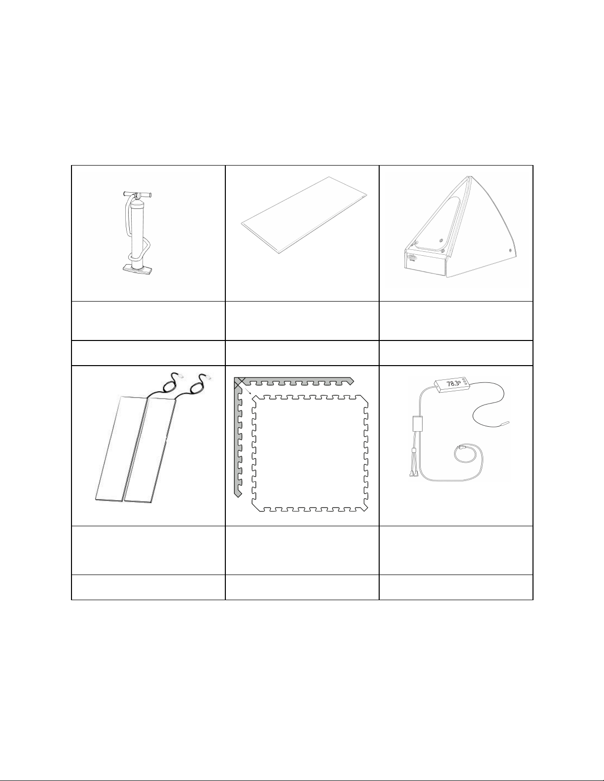
1 x Air Inflation
Pump
1 x Base Drip Mat
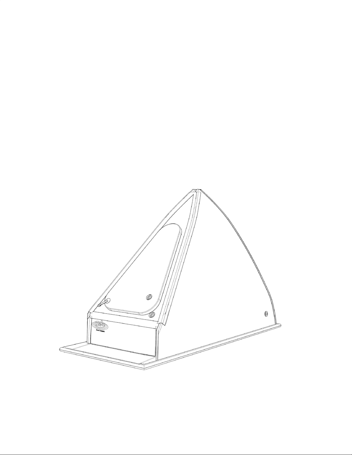
1 x Tank Body
#1
#2
#3
2 x Heating Pads
15 x Foam Tiles
1 x Temperature Controller
*Grounding Probe pre-plugged
inline
#4a & #4b
#5
#6
6
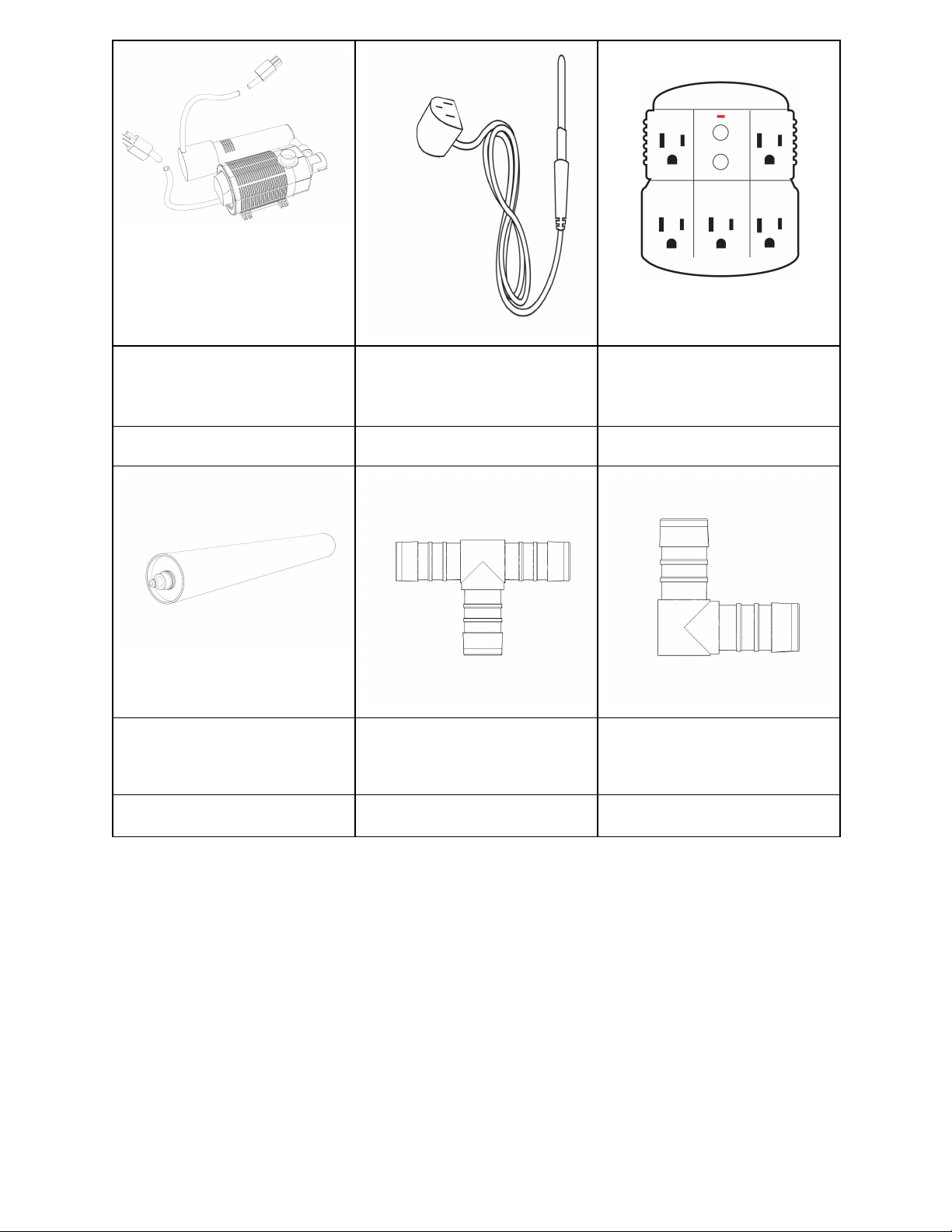
1 x Water Pump & 1 x UV
Water Filter
*Pre-connected
1 x Grounding Probe
*Pre-plugged to Temperature
Controller
1 x GFCI Adapter
*120V models only
#7a & #7b
#8
#9
1 x Filter Bag
*Additionals incl. w/ Float Ready
Package
1 x T Fitting
*Pre-inserted in Filtration Hose
1 x 90 Degree Fitting
*Pre-inserted in Filtration Hose
#10
#11
#12
7
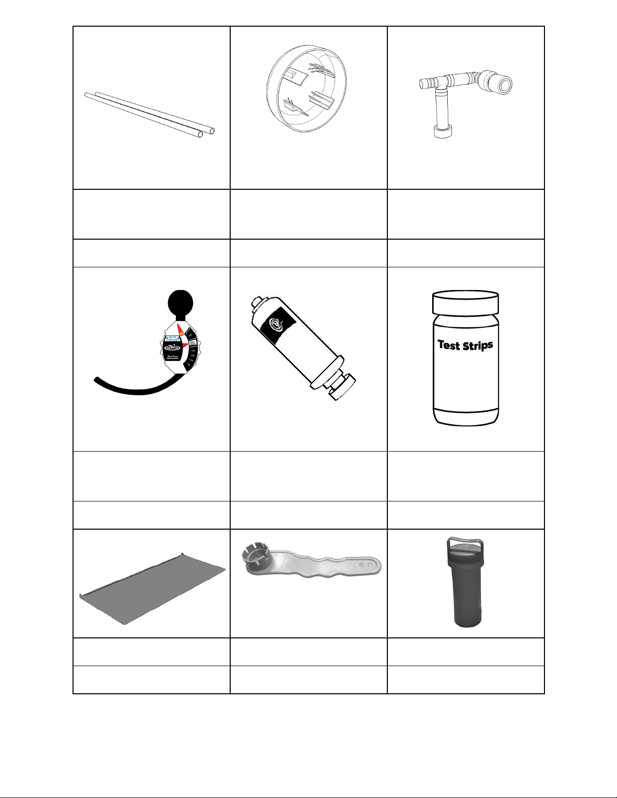
2 x Water Filtration Hose
*T & 90 Deg. fittings pre-inserted
4 x Vent Caps
1 x Pump Manifold
*Pre-assembled with Water
Pump Fittings
#13
#14
#15
1 x Hydrometer
1 x Inline Carbon Filter
1 x Water Test Strips
*Additionals incl. w/ Float Ready
Package
#16
#17
#18
1 x Step Drip Mat
1 x Air Valve Wrench
1 x Repair Kit
#19
#20
#21
8
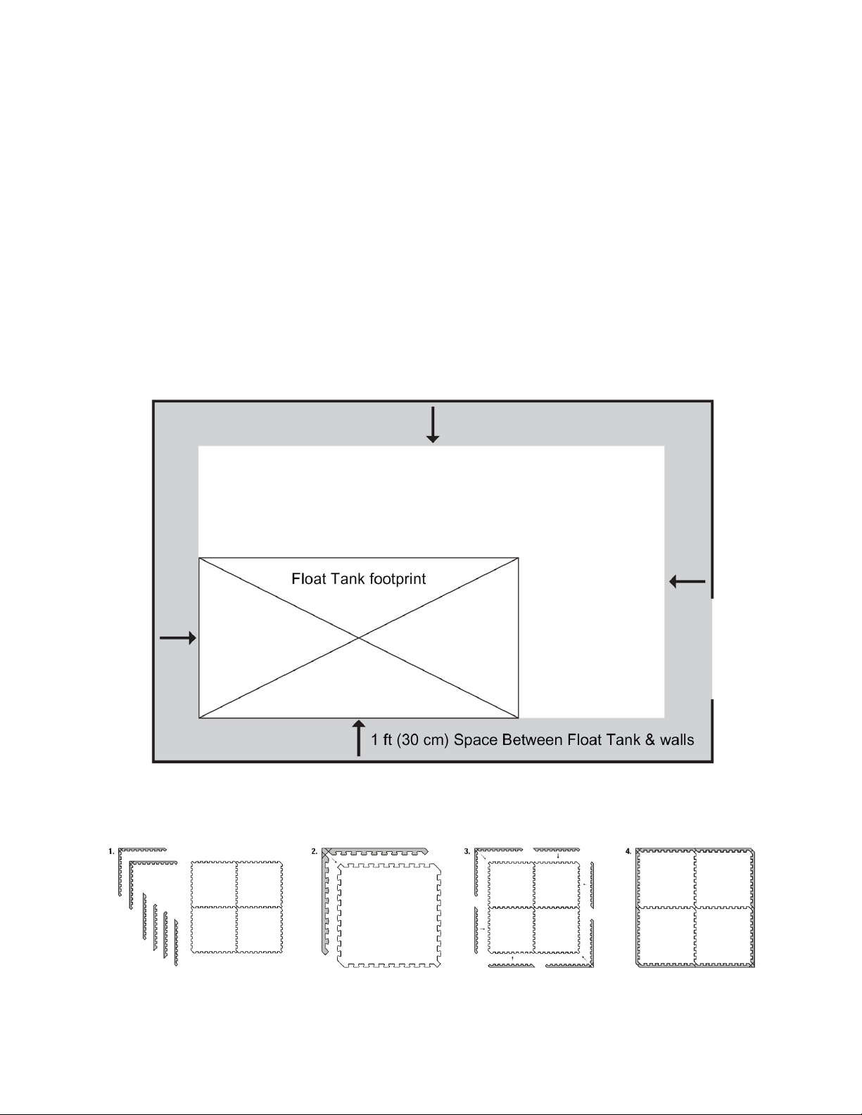
Step 1 - CHOOSE PROPER PLACEMENT
It is important you carefully consider the placement of your Tank before you
start the installation. Once installation is completed and the Tank has been
filled, relocating the Tank will require transferring and storing 200 gallons
(757 L) of water and Epsom salt solution.
★Choose a preferred location that will stay between 70° and 90°
Fahrenheit (21° to 32° Celsius).
★Allow at least 1 ft (30 cm) of space between the Float Tank and the
room’s walls to allow for maintenance and cleaning.
★Consider the space between the front, door side, of the Float Tank
and the wall to allow for entering and exiting.
1. Interlock the Foam Tiles (#5) in a 3 x 5 configuration
a. You may need to rotate the tiles to align for the proper fit
2. Position the connected Foam Tiles (#5) in the room to the preferred
location
9
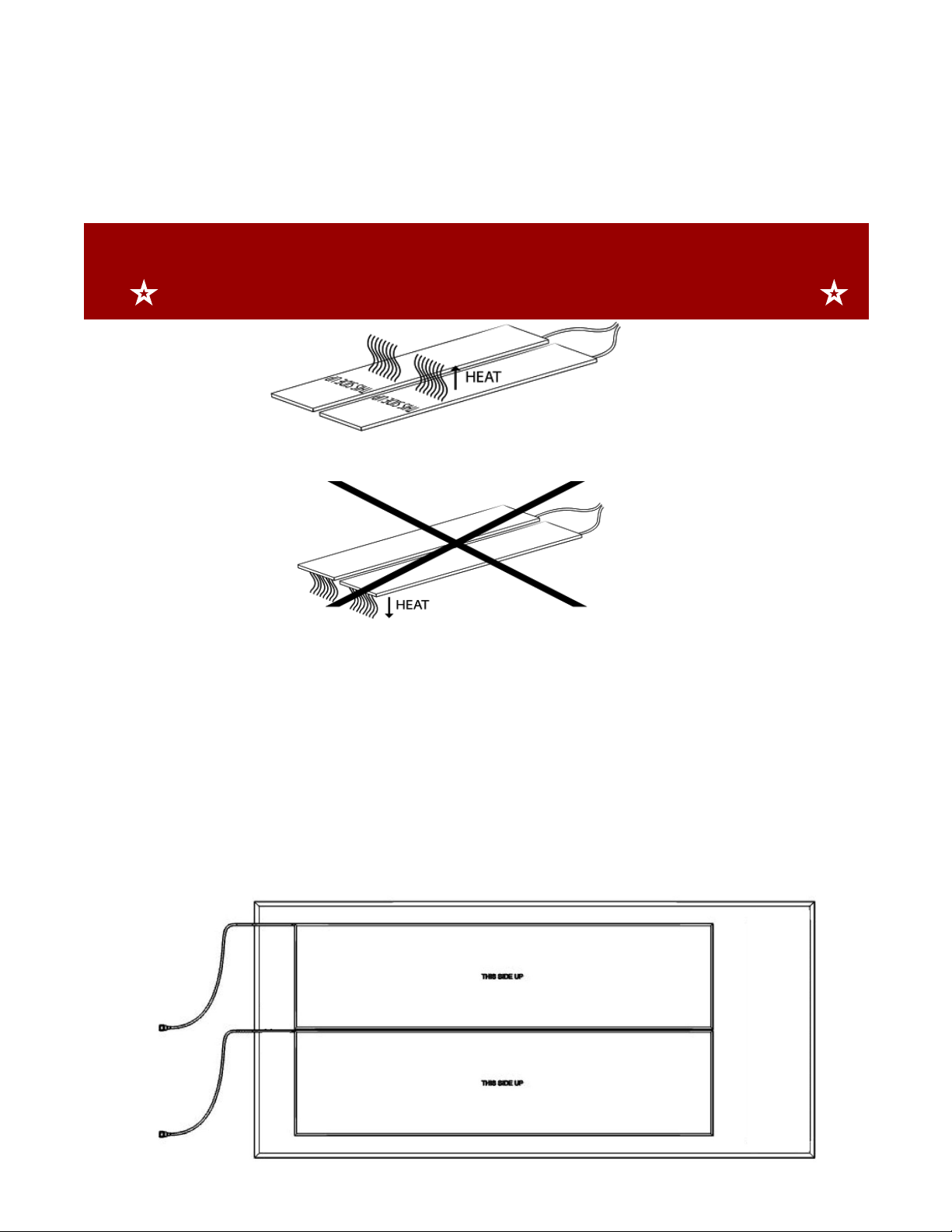
Step 2 - PLACE HEATER PADS
The Heating Pads (#4a & #4b) are placed on top of the Foam Tiles (#5),
and will radiate heat up into the water.
IMPORTANT
☆ VERIFY THE PADS ARE THE CORRECT SIDE UP ☆
1. Place Heating Pads ( #4a & #4b) on top of the Foam Tiles (#5):
a. Inside edges of the Pads should touch, but not overlap
2. “This Side Up” sticker identifies proper side is facing up
3. Orient Heating Pads( #4a & #4b) on top of the Foam Tiles (#5) so the
electrical cords face the rear side of the Tank (opposite the Door
Side)
4. Pads will be located toward the rear edge of the foam tiles:
10
Other manuals for Tank
1
Table of contents
Popular Bathtub manuals by other brands


Lyons
Lyons Elite ETLxx663219 Series manual

Woodbridge
Woodbridge BJ500 Installation and care guide

Whirlpool
Whirlpool Ariel ARL-702 installation manual

TEIKO
TEIKO EXCELLENT DUO user manual

American Standard
American Standard Colony 5-1/2' x 32" Specification sheet

American Standard
American Standard 3052OD.X0X Installation instructions and owner's manual


