Zenisu Keisoku,Inc. ZS-6224P User manual

- 1 -
ZS-6224 Series
USB-PIO Adapter
User’s Manual
ZenisuKeisoku,Inc.
Zip code: 18 -0027
2-1 - 7, Honmachi, Fuchu, Tokyo, Japan
TEL: +81-(0)42- 68-2126
FAX: +81-(0)42- 64-0067
URL http://www.zenisu.co.jp/

- 2 -
◆ Table of contents ◆
1.Outline
..................................................................................................................................
2.Specification
........................................................................................................................
2.1.Operation environment ....................................................................................................
2.2.USB ...................................................................................................................................
2. .Product specification ........................................................................................................ 4
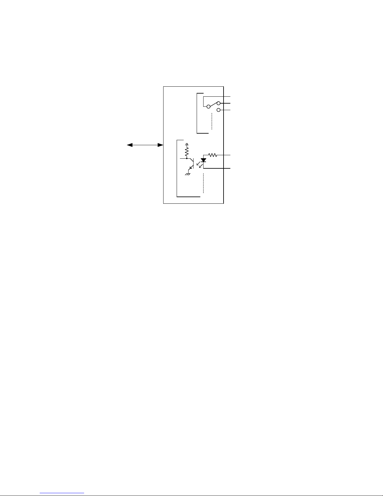
2.4.Relay .................................................................................................................................. 4
2.5.Photocoupler ..................................................................................................................... 4
2.6.Appearance ....................................................................................................................... 4
.Install
.................................................................................................................................... 5
.1.Device driver ..................................................................................................................... 5
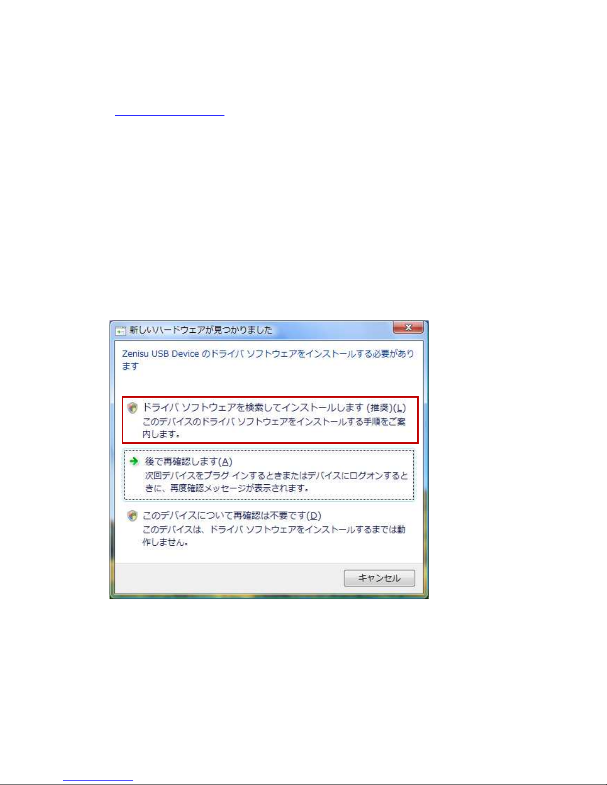
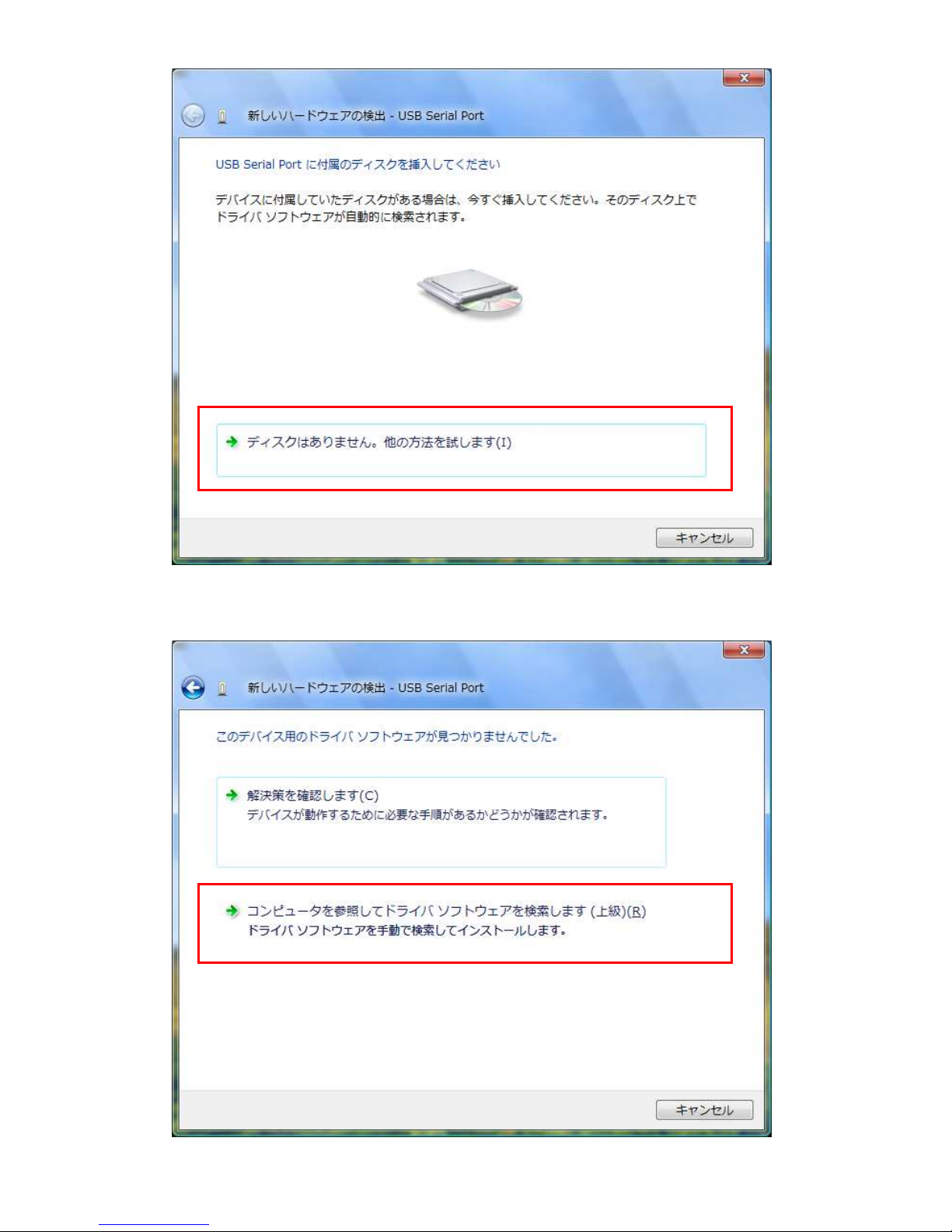
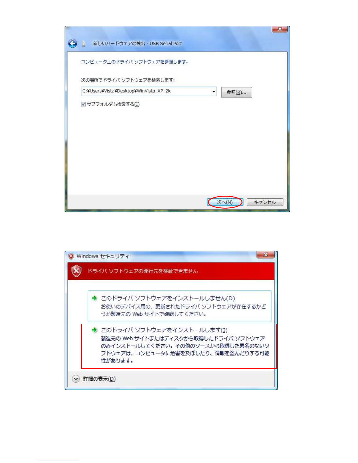
.2.Windows Vista ................................................................................................................... 5
. .Windows XP/2000 ........................................................................................................... 12
4.Operation
............................................................................................................................ 17
4.1.Preparation ..................................................................................................................... 17
4.2.Function .......................................................................................................................... 17
4.2.1. FT_Open .................................................................................................................. 17
4.2.2. FT_Close .................................................................................................................. 17
4.2. . FT_SetBitMode ....................................................................................................... 18
4.2.4. FT_SetBaudRate ..................................................................................................... 18
4.2.5. FT_Write .................................................................................................................. 19
4.2.6. FT_GetBitMode ....................................................................................................... 19
5.Connector
........................................................................................................................... 20
6.Warranty
............................................................................................................................. 21

- 3 -
1.Outline
ZS-6224 is a unit built-in 4 relays and 1 photocoupler.
It is possible to perform insulation between circuits, level conversion, etc, by connecting relays
and photocoupler.
4
4
ZS-6224
USB
3.9KΩ
2.Specification
2.1.Operation environment
PC : IBM PC/AT compatible machine (USB required)
OS : Microsoft Windows 2000 , XP , Vista
2.2.USB
Compliant with USB2.0

- 4 -
2. .Product specification
Model ZS-6224P ZS-6224S
Feature Printed circuit boarded type Small case built-in type
Data connector
50-core flat cable 50-core flat cable
Power supply
USB bus power (DC4.75V to 5.25V 100mA or less)
Environment
Temperature 0℃ to 50℃ Humidity 85% or less
Temperature 0℃ to 50℃ Humidity 85 or less
Storage Temp
-20℃ to 80℃ -20℃ to 80℃
Size 100×74×20H 150×100×30H
Accessory Data connector x 1 57-30240 Data connector x 1 57-30240
2.4.Relay
Relay G5V-1
Resistance 100mΩ or less
Switching part rated load
AC125V 0.5A、 DC24V 1A
Operation time 5ms or less
Recovery time 5ms or less
2.5.Photo coupler
Photo coupler PS2801-4
Input voltage DC5V to DC24V
2.6.Appearance
Front side View
Back side View
1
50

- 5 -
.Install
.1.Device driver
Please download the device driver corresponding to each OS from our website below.
http://www.zenisu.co.jp
.2.Windows Vista
In order to use this product, it is necessary to install hardware and device drivers.
① Turn on the power to the PC and start Windows.
② Connect the PC and this product with USB cable.
③ Install the device driver.
④ Installation is completed.
The “Device driver installation method” is explained as below. The display of sentences may
differ depending on the personal computer, but it is basically the same.
When connecting this product to the computer at first, the following screen will be
displayed.
Click “Search and install driver software”.

- 6 -
Click “ There is no disc, try other method”.
Click “Refer to the PC and search the driver software”.

- 7 -
Refer to the downloaded file and click the “NEXT” button.
The following screen will be displayed “It can not verify the publisher of the driver software”,
but there is no problem. Click “Install this driver software”.

- 8 -
Click “Close” button.
The following screen will be displayed.
Click “Search and install driver software”.

- 9 -
Click “ There is no disc, try other method”.
Click “Refer to the PC and search the driver software”.

- 10 -
Refer to the download file and click the “NEXT” button.
There is no problem. Click “Install this driver software”.

- 11 -
Installation is completed, click “Close” button.

- 12 -
. .Windows XP/2000
In order to use this product, it is necessary to install hardware and device drivers.
⑤ Turn on the power to the PC and start Windows.
⑥ Connect the PC and this product with USB cable.
⑦ Install the device driver.
⑧ Installation is completed.
The “Device driver installation method” is explained as below. The display of sentences may
differ depending on the personal computer, but it is basically the same.
When connecting this product to the computer at first, the following screen will be
displayed.
Select “Install from the list or specific location” and click the “NEXT” button.

- 13 -
Select “Search for the driver in the following location”, refer to the downloaded driver and
click the “NEXT” button.
The following screen will be displayed, but there is no problem click “Continue” button.

- 14 -
The following screen will be displayed if device driver installation is normally completed.
Click “Finish” button. Since it may be required to restart depending on the configuration of
the PC, restart according to the instructions on the screen. Even if you connect to the
computer from the next time, these screen will not be displayed.
The following screen will be displayed.
Select “Install from the list or specific location” and click the “NEXT” button.

- 15 -
Select “Search for the driver in the following location”, refer to the downloaded driver and
click the “NEXT” button.
There is no problem, click the “Continue” button.

- 16 -
The following screen will be displayed if.
Click “Finish” button. Since it may be required to restart depending on the configuration of
the PC, restart according to the instructions on the screen. Even if you connect to the
computer from the next time, these screen will not be displayed.

- 17 -
4.Operation
4.1.Preparation
ZS-6224 uses API made by FTDI inc, depending on each programming language, include
the following files.
Visual Basic :D2XX_Module.bas
Visual C++ :FTD2XX.H、FTD2XX.lib
Delphi :D2XXUnit.pas
4.2.Function
In order to control the relay and input the photocoupler, use the following function.
FT_Open :Open the USB port.
FT_Close :Close the USB port.
FT_SetBitMode :Set the I/O of the 8-bit port.
FT_SetBaudRate :Set the rewrite time of 8 bits.
FT_Write :Turn relay ON/OFF.
FT_GetBitMode :Load the photocoupler.
4.2.1. FT_Open
Function
Open the USB port and initialized.
Format
FT_Open (int iDevice, FT_HANDLE *ftHandle)
iDevice :Set “0”.
ftHandle :If FT_Open is successful, the handle number will be returned.
Use this handle number when using other functions.
Return value
FT_OK :In case of “0”, success.
Other than “0” :Error
4.2.2. FT_Close
Function
Close the USB port and execute driver termination processing.
Format
FT_Close (FT_HANDLE ftHandle)
ftHandle :Set the handle number.
Return value
FT_OK :In case of “0”, success.
Other than “0” :Error

- 18 -
4.2. . FT_SetBitMode
Function
Set of I/O of 8 bits.
Format
FT_SetBitMode (FT_HANDLE ftHandle, UCHAR ucMask, UCHAR ucMode)
ftHandle :Set the handle number.
ucMask :Set HEX(0F), 0:Input 1:Output
In the ZS-6224, the upper 4 bits are input to the photocoupler
and lower 4 bits are set to the relay output. Since it is set “0F”.
ucMode :Set “1”
Return value
FT_OK :In case of “0”, success.
Other than “0” :Error
4.2.4. FT_SetBaudRate
Function
Set the rewrite time of output data.
Format
FT_SetBaudRate (FT_HANDLE ftHandle, DWORD dwBaudRate)
ftHandle :Set the handle number.
DwBaudRate :Set “9600”
When set to 9600, data is rewritten at 1 / (9600 × 16) = 6.51 µs
cycle. If there is no data in the buffer, the previous output is
continued.
Return vale
FT_OK :In case of “0”, success.
Other than “0” :Error

- 19 -
4.2.5. FT_Write
Function
Set the relay ON/OFF.
Format
FT_Write (FT_HANDLE ftHandle, LPVOID lpBuffer, DWORD dwBytesToWrite,
LPDWORD lpdwBytesWritten)
ftHandle :Set the handle number.
lpBuffer :Set“1” when the relay is ON, “0” is OFF, and execute Byte output.
Bit assignments are as follows.
D0D3
Relay_1
Relay_2
Relay_3
Relay_4
D7
0 0 0 0
dwBytesToWrite :Set “1”.
lpdwBytesWritten :Set “1”.
Return value
FT_OK :In case of “0”, success.
Other than “0” :Error
4.2.6. FT_GetBitMode
Function
Load photocoupler
Format
FT_Read (FT_HANDLE ftHandle, PUCHAR pucMode)
ftHandle :Set the handle number
pucMode :Set”1” when the photocoupler is driving, “0” is not driving.
Bit assignments are as follows.の割り当ては以下の通りです。
D0D4
Photocoupler_1
Photocoupler_2
Photocoupler_3
Photocoupler_4
D7
Return value
FT_OK :In case of “0”, success.
Other than “0” :Error

- 20 -
5.Connector
Connector (
57LE-40240-7700-FA
)
Signal Pin No. Signal
Relay 1_COM 1 13 Relay 3_COM
Relay 1_NO 2 14 Relay 3_NO
Relay 1NC 3 15 Relay 3_NC
Relay 2_COM 4 16 Relay 4_COM
Relay 2_NO 5 17 Relay 4_NO
Relay 2_NC 6 18 Relay 4_NC
GND 7 19 GND
Photocoupler 1_IN+
8 20 Photocoupler 1_IN-
Photocoupler 2_IN+
9 21 Photocoupler 2_IN-
Photocoupler 3_IN+
10 22 Photocoupler 3_IN-
Photocoupler 4_IN+
11 23 Photocoupler 4_IN-
GND 12 24 GND
Relay:
COM
NC
NO
Photocoupler:
+
-
This manual suits for next models
1
Table of contents
Other Zenisu Keisoku,Inc. Adapter manuals
Popular Adapter manuals by other brands

TRENDnet
TRENDnet Powerline 1300 AV2 Adapter with Built-in... user guide

StarTech.com
StarTech.com USB32HDEH quick start guide

Gossen MetraWatt
Gossen MetraWatt AT3-II S operating instructions

Metz
Metz Pentax SCA 3701 M2 instructions

Treetop Circuits
Treetop Circuits SB-75 owner's manual

Sitecom
Sitecom PRO LINE CN-5506 user manual