Zenoah BKZ315L User manual

BKZ315L
OPERATOR’S MANUAL
BRUSHCUTTER
114 06 79-38 (1811)
• Before using our products,
please read this manual
carefully to understand the
proper use of your unit.
• Keep this manual handy.
G
B
01-BKZ315L_GB_cs6_二.indd 1 18/09/03 11:50

GB-2
BKZ315L
1. Parts location
Contents
1. Parts location ...................................................2
2. Specification ....................................................3
3. Symbols on the machine..................................3
4. Warning labels on the machine .......................4
5. For safe operation ............................................5
6. Set up...............................................................9
7. Fuel ................................................................13
8. Operation .......................................................14
9. Maintenance ..................................................19
10. Storage...........................................................22
11. Troubleshooting..............................................23
12. Disposal .........................................................23
7.
5.
9.
11.
28.
29.
26. 27.
23. 24. 25.
12.
13.
14.
15.
16.
17. 21.
20.
19.
30.
18.
4.
1.
6.
22.
2.
3.
8.
10.
(1) Carburetor
(2) Air cleaner
(3) Fuel tank
(4) Spark plug
(5) Choke lever
(6) Starter knob
(7) Muffler
(8) Fuel tank cap
(9) Debris guard
(10) Blade
(11) Gear case
(12) Drive shaft
(13) Loop handle
(14) Throttle lever
(15) Engine stopping switch
(16) Flexible shaft
(17) Throttle cable
(18) Frame
(19) Back cushion
(20) Hanging belt
(21) Wire clamp
(22) Air purge
(23) Blade cover
(24) Goggle
(25) Bag
(26) Socket wrench
(27) Hex wrench
(28) Driver
(29) Operator’s manual
(30) Shoulder strap
SAFETY FIRST
Instructions contained in warnings within this manual marked
with a symbol concern critical points which must be taken into
consideration to prevent possible serious bodily injury, and for
this reason you are requested to read all such instructions care-
fully and follow them without fail.
NOTES ON TYPES OF WARNINGS IN THE MANUAL
WARNING
This mark indicates instructions, which must be followed in order
to prevent accidents, which could lead to serious bodily injury
or death.
IMPORTANT
This mark indicates instructions, which must be followed, or it
leads to mechanical failure, breakdown, or damage.
NOTE
This mark indicates hints or directions useful in the use of the
product.
01-BKZ315L_GB_cs6_二.indd 2 18/09/03 11:50

GB-3
BKZ315L
G
B
2. Specification
3. Symbols on the machine
The port to refuel the “MIX GASOLINE”
Position: FUEL TANK CAP
The direction to close the choke
Position: AIR CLEANER COVER
The direction to open the choke
Position: AIR CLEANER COVER
Model BKZ315L
Handle Type Loop
Dry Weight (*1) kg 8.4
Overall size (L x W x H) (*2) mm 2655 x 305 x 370
Standard blade 10-inch, Chip saw
Power Transmission Method Automatic centrifugal clutch, spiral gear
Reduction Rate 1.67
Blade Rotating Direction Counterclockwise (from operator’s view)
Blade mounting bolt size M7
Main pipe (Outer diameter mm) Aluminum (Φ24)
Engine
Model name GZ30N
Displacement cc 29.5
Fuel tank capacity L 1.1
Fuel Used Lubricating oil mixed gasoline
Lubricating Oil Used 2-stroke engine oil
Mixing rate GASOLINE 50 : OIL 1
When using ZENOAH genuine oil
Carburetor Diaphragm-type rotary valve
Sparking Method Fly wheel magnet (CDI)
Spark Plug NGK CMR7H-10
Starting Method Pressure-accumulator type recoil starter (EZ start)
Stopping Method Ground a primary coil
(*1) Excluding blade and fuel
(*2) ITotal length including blade with assembled engine and shaft unit.
Note that detailed specifications of the product might differ from the information described herein due to modifications, etc.
For safe operation and maintenance, symbols are carved in relief on the machine. According to these indications,
please be careful not to make a mistake.
01-BKZ315L_GB_cs6_二.indd 3 18/09/03 11:50

GB-4
BKZ315L
4. Warning labels on the machine
Never modify your machine.
We won’t warrant the machine, if you use
the remodeled brushcutter or if you don’t
observe the proper usage written in the
manual.
If warning label peels off or becomes soiled
and impossible to read, you should contact the
dealer from which you purchased the product
to order new labels and affix them in the re-
quired location(s).
Warning / Attention
Location
①
(1) Read operator’s manual before operating this machine.
(2) Wear head, eye and ear protection.
(3) Wear foot protection.
(4) Wear gloves.
(5) Beware of thrown objects.
(6) Warning / Attention
(7) Keep all children, bystanders and helpers 15 meters away from the brushcutter.
(1) (2) (3) (4) (5) (6) (7)
③
The engine may start in retard
of pulling the recoil starter.
Hold the machine firmly till the
engine start.
②
Keep the cutting
blade around clear or
person or object when
start the engine.
01-BKZ315L_GB_cs6_二.indd 4 18/09/03 11:50

GB-5
BKZ315L
G
B
1. Read this manual carefully
until you completely under-
stand and follow all safety and
operating instructions.
2. Keep this manual handy so
that you may refer to it later
whenever any questions arise.
Also note, if you have any
questions which cannot be
answered herein, contact the
dealer from whom you pur-
chased the product.
3. Always be sure to include this
manual when selling, lending,
or otherwise transferring the
ownership of this product.
4. Never allow children or any-
one unable to fully understand
the directions given in the
manual to use the machine.
■WORKING CONDITION
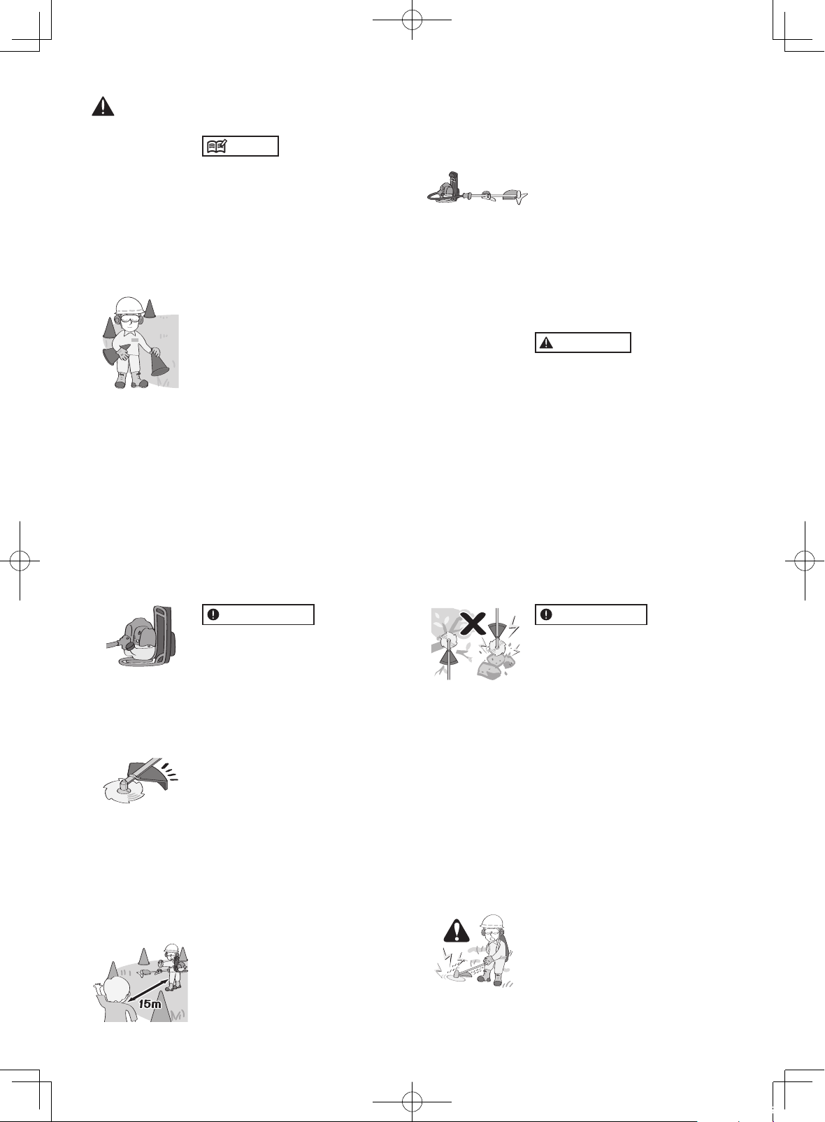
1. When using the product, you
should wear proper clothing and
protective equipment.
(1) Helmet
(2) Ear protectors
(3) Protection goggles or face
protector
(4) Thick work gloves
(5) Non-slip-sole work boots
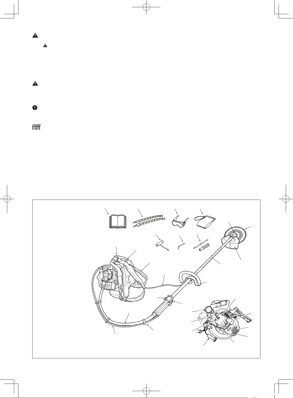
2. And you should carry with you.
(1) Attached tools
(2) Properly reserved fuel
(3) Spare blade
(4) Things to notify your working
area (rope, warning signs)
(5) Whistle (for collaboration or
emergency)
(6) Hatchet or saw (for removal of
obstacles)
3. Do not wear loose clothing, jew-
elry, short trousers, sandals, or
go barefoot. Do not wear any-
thing which might be caught by
a moving part of the unit. Secure
hair so it is above shoulder
length.
■
WORKING CIRCUMSTANCE
1. Never start the engine inside a
closed room or building. Exhaust
gases contain dangerous carbon
monoxide.
2. Never use the product,
(1) When the ground is slippery or
when you can’t maintain a
steady posture.
(2) At night, at times of heavy fog,
or at any other times when your
field of vision might be limited
and it would be difficult to gain
a clear view of the working
area.
(3) During rain storms, during light-
ning storms, at times of strong
or gale-force winds, or at any
other times when weather condi-
tions might make it unsafe to use
the product.
■WORKING PLAN
1. You should never use the product
when under the influence of al-
cohol, when suffering from ex-
haustion or lack of sleep, when
suffering from drowsiness as a
result of having taken cold med-
icine or at any other time when a
possibility exists that your judg-
ment might be impaired or that
you might not be able to operate
the product properly and in a
safe manner.
2. When planning your work sched-
ule, allow plenty of time to rest.
Limit the amount of time over
which the product is to be used
continuously to somewhere
around 30 ~ 40 minutes per ses-
sion, and take 10 ~ 20 minutes
of rest between work sessions.
Also try to keep the total amount
of work performed in a single day
under 2 hours or less.
WARNING
1. If you don’t observe the working
time, or working manner (See
“USING THE PRODUCT”), Re-
petitive Stress Injury (RSI) could
occur.
If you feel discomfort, redness
and swelling of your fingers or
any other part of your body, see
a doctor before getting worse.
2. To avoid noise complaints, in
general, operate product be-
tween 8 a.m. and 5 p.m. on
weekdays and 9 a.m. to 5 p.m.
on weekends.
5. For safe operation
01-BKZ315L_GB_cs6_二.indd 5 18/09/03 11:50

GB-6
BKZ315L
the cutting attachment begins to
rotate as soon as the engine is
started by putting the throttle
lever into the start position. When
starting the engine, place the
product onto the ground in a flat
clear area and hold it firmly in
place so as to ensure that neither
the cutting part nor the throttle
lever come into contact with any
obstacle when the engine
starts.
WARNING
Never place the throttle lever into
the high-speed position when
starting the engine.
3. After starting the engine, check
to make sure that the cutting at-
tachment stops rotating when the
throttle is moved fully back to its
original position. If it continues to
rotate even after the throttle lever
has been moved fully back, turn
off the engine and take the unit
to your authorized ZENOAH
servicing dealer for repair.
■USING THE PRODUCT
IMPORTANT
Cut only materials recommended by
the manufacturer. And use only for
tasks explained in the manual.
1. Grip the handles firmly with both
hands using your whole hand.
Place your feet slightly apart
(slightly further apart than the
width of your shoulders) so that
your weight is distributed evenly
across both legs, and always be
sure to maintain a steady, even
posture while working.
2. Keep cutting attachment below
waist level.
3. Maintain the speed of the engine
at the level required to perform
cutting work, and never raise the
speed of the engine above the
level necessary.
4. If the unit starts to shake or vi-
brate, turn off the engine and
check the whole unit. Do not use
it until the trouble has been prop-
erly corrected.
5. Keep all parts of your body away
NOTE
Check and follow the local regula-
tions as to sound level and hours of
operations for the product.
■BEFORE STARTING THE
ENGINE
1. The area within a perimeter of 15
m of the person using the prod-
uct should be considered a
hazardous area into which no
one should enter. If necessary,
yellow warning rope, warning
signs should be placed around
the perimeter of the area. When
work is to be performed simulta-
neously by two or more persons,
care should also be taken to
constantly look around or other-
wise check for the presence and
locations of other people working
so as to maintain a distance
between each person sufficient
to ensure safety.
2. Check the condition of working
area to avoid any accident by
hitting hidden obstacles such as
stumps, stones, cans, or broken
glass.
IMPORTANT
Remove any obstacle before begin-
ning work.
3. Inspect the entire unit for loose
fasteners and fuel leakage. Make
sure that the cutting attachment
is properly installed and se-
curely fastened.
4. Be sure the cutting attachment
guard is firmly attached in
place.
5. Always use the harness. Adjust
the harness for comfort before
starting the engine. The harness
should be adjusted so the left
hand can comfortably hold the
handlebar grip approximately
waist high.
■STARTING THE ENGINE
1. Keep bystanders and animals at
least 15 m away from the operat-
ing point. If you are approached,
immediately stop the engine.
2. The product is equipped with a
centrifugal clutch mechanism, so
5. For safe operation
01-BKZ315L_GB_cs6_二.indd 6 18/09/03 11:50

GB-7
BKZ315L
G
B
from rotating cutting attachment
and hot surfaces.
6. Never touch the muffler, spark
plug, or other metallic parts of
the engine while the engine is in
operation or immediately after
shutting down the engine. Doing
so could result in serious burns
or electrical shock.
■IF SOMEONE COMES
1. Guard against hazardous situa-
tions at all times. Warn adults to
keep pets and children away
from the area. Be careful if you
are approached. Injury may re-
sult from flying debris.
2. If someone calls out or otherwise
interrupts you while working, al-
ways be sure to turn off the en-
gine before turning around.
■MAINTENANCE
1. In order to maintain your product
in proper working order, perform
the maintenance and checking
operations described in the
manual at regular intervals.
2. Always be sure to turn off the
engine and disconnect the spark
plug wire before performing any
maintenance or checking proce-
dures.
WARNING
The metallic parts reach high
temperatures immediately after
stopping the engine.
3. When replacing the cutting at-
tachment or any other part, or
when replacing the oil or any
lubricant, always be sure to use
only ZENOAH products or
products which have been
certified by ZENOAH for use
with the ZENOAH product.
4. In the event that any part must
be replaced or any maintenance
or repair work not described in
this manual must be performed,
please contact a representative
from the store nearest ZENOAH
authorized servicing dealer for
assistance.
5. Do not use any accessory or at-
tachment other than those bear-
ing the ZENOAH mark and rec-
ommended for the unit.
6. Under no circumstances should
you ever take apart the product
or alter it in any way. Doing so
might result in the product be-
coming damaged during opera-
tion or the product becoming
unable to operate properly.
■HANDLING FUEL
1. The engine of the ZENOAH
product is designed to run on a
mixed fuel, which contains high-
ly flammable gasoline. Never
store cans of fuel or refill the tank
of the unit in any place where
there is a boiler, stove, wood fire,
electrical sparks, welding sparks,
or any other source of heat or fire
which might ignite the fuel.
2. Never smoke while operating the
unit or refilling its fuel tank.
3. When refilling the tank, always
turn off the engine and allow it to
cool down. Take a careful look
around to make sure that there
are no sparks or open flames
anywhere nearby before refuel-
ing.
4. Wipe spilled fuel completely us-
ing a dry rag if any fuel spillage
occurs during refueling.
5. After refueling, screw the fuel
cap back tightly onto the fuel
tank and then carry the unit to a
spot 3 m or more away from
where it was refueled before
turning on the engine.
■TRANSPORTATION
1. When hand-carrying the product,
cover over the cutting part if
necessary, lift up the product
and carry it paying attention to
the blade.
2. Never transport the product over
rough roads over long distances
by vehicle without removing all
fuel from the fuel tank. If doing
so, fuel might leak from the tank
during transport.
WARNING
■CONTROLLING BLADE
THRUST
Blade thrust can cause serious
personal injury. Carefully study
this section. It is important that
5. For safe operation
01-BKZ315L_GB_cs6_二.indd 7 18/09/03 11:50

GB-8
BKZ315L
5. For safe operation
you understand what causes
blade thrust, how you can reduce
the chance of blade thrust and
how you can remain in control of
the unit if blade thrust does oc-
cur.
1. What causes blade thrust:
Blade thrust can occur when the
moving blade contacts an object
that it cannot cut. This contact
causes the blade to stop for an in-
stant and then suddenly move or
”bounce” away from the object that
was hit. The operator can lose con-
trol of the unit and the blade can
cause serious personal injury to the
operator or any person nearby if the
blade contacts any part of the
body.
2. How you can reduce the chance
of blade thrust:
(1) Recognize that blade thrust can
happen. By understanding and
knowing about bounce, you can
help eliminate the element of
surprise.
(2) Cut fibrous weeds and grass
only. Do not let the blade contact
materials it cannot cut such as
hard, woody vines and brush or
rocks, fences, metal, etc
(3) Be extra prepared for blade
thrust if you must cut where you
cannot see the blade making
contact such as in areas of
dense growth.
(4) Keep the blade sharp. A dull
blade increase the chance of
blade thrust.
(5) Avoid feeding the blade too
rapidly. The blade can bounce
away from material being cut if
the blade is fed faster than its
cutting capability.
(6) Cut only from your right to your
left.
(7) Keep your path of advance clear
of material that has been cut
and other debris.
3. How you can maintain the best
control:
(1) Keep a good, firm grip on the
unit with both hands. A firm grip
can help neutralize bounce.
Keep your right and left hands
completely around the respec-
tive handles.
(2) Keep both feet spread apart in
a comfortable stance and yet
braced for the possibility that
the unit could bounce. Do not
overreach. Keep firm footing
and balance.
01-BKZ315L_GB_cs6_二.indd 8 18/09/03 11:50

GB-9
BKZ315L
G
B
6. Set up
WARNING
• Assemble each part correctly. Wrong assembly
might cause an accident.
• If you cannot do the assembling yourself, consult
the shop where you bought this product.
■INSTALLING THE SHOULDER STRAP
1. Hook the upper part of the shoulder strap at the notch
on the top of the frame and pass it through the buckle
as shown in the Figure, then secure it firmly.
2. Put the hook at the lower part of the shoulder strap in
the strap installing location at the bottom of the frame.
(1) Buckle
(2) Frame
(3) Hook
(4) D-ring
■CONNECTING THE FLEXIBLE SHAFT
1. Remove the clamping bolt (M5xL9) in the center of
the end of the joint, and loosen the fastening bolt
(M5xL20) and the screw (M5xL18) for mounting the
throttle lever.
2. Insert the main pipe into the joint while turning it
clockwise and counterclockwise slightly.
3. Align the safety-lock hole of the joint with the hole of
the main pipe, screw the clamping bolt and fasten it
tightly.
4. Tighten the fastening clumping bolt (7) of the joint,
and fix the main pipe firmly.
[Tightening torque]
4.9 to 7.8 N•m (0.5~0.8 kg•m)
5. Screw the throttle-lever mounting screw, and fasten
it tightly.
(1) Screw (M5xL18) (5) Throttle lever
(2) Clamping bolt (M5xL9) (6) Joint
(3) Safety-lock hole (7) Clamping bolt
(4) Main pipe (M5xL20)
01-BKZ315L_GB_cs6_二.indd 9 18/09/03 11:50

GB-10
BKZ315L
6. Set up
■MOUNTING THE HANDLE
1. Mount the loop handle on the main pipe in accor-
dance with the serial-number label. Turn the grip and
tighten it slightly, then fasten the hanger plate to-
gether in the position shown in SE8.
2. Adjust the position of the loop handle to the position
where you can work easily, and tighten the loop
handle firmly.
(1) Grip
(2) Hanger plate
WARNING
• Tighten the grip firmly. If the grip becomes loose,
it might move while you are working, causing
danger.
• Do not loosen or twist the grip while you are work-
ing.
• Always stop the engine and make sure the blade
has stopped before adjusting the position of the
loop handle.
■INSTALLING HANGING BELT
1. Put the hook at the hanging belt in the D-ring at the
shoulder strap and adjust the length where it is easy
to work.
2. Carrying the unit on the back, put the other side of
the hook in the hanger plate.
(1) Shoulder strap
(2) Hook
(3) Hanger plate
(4) Loop handle
(2)
(2)
(3) (4)
(1)
■INSTALLING DEBRIS GUARD
WARNING
Do not use this machine without the debris guard.
Fit the top of the debris guard to the gear case, install
the debris guard on the main pipe with the accessory
clamp, and tighten the debris guard evenly with two
Phillips screws (M5xL30).
[Tightening torque]
1 to 2 N•m (10 to 20 kgf•cm)
(3)
(4)
(5)
(2)
(1)
(6)
(1) Gear case
(2) Clamp
(3) Phillips screw
(M5xL30)
(4) Main pipe
(5) Safety-guard
cover
(6) Fit this part to
the gear case.
■MOUNTING THE CUTTING BLADE
WARNING
• Be sure to stop the engine before demounting
and remounting the cutting blade. Never try to
touch the blade while the engine is running.
• Always use Zenoah genuine cutting blades and
fittings for replacement.
• When demounting and remounting the cutting
blade, firmly secure the brush cutter and wear
heavy-duty gloves.
• The cutter blade rotates left (counterclockwise)
when viewed from the gear case. When the mount-
ing side of a cutting blade is predetermined, select
the mounting side correctly when mounting it.
Particularly, when a chip saw blade is mounted
reversely, the teeth may be chipped and fly away.
This is very dangerous.
• Be sure to clean the gear shaft thread complete-
ly before mounting the cutting blade. Dirt and
sand on the thread will cause loosening of the
blade mount. This is very dangerous.
• Never use a power impact driver or other high
torque tool or put all of your weight to fasten the
mounting bolt of the cutting blade. An excessive
tightening force will damage the mounting bolt or
the gear shaft and cause hazardous accident or
personal injury. Be sure to use the accompanying
socket wrench and tighten them firmly.
01-BKZ315L_GB_cs6_二.indd 10 18/09/03 11:50

GB-11
BKZ315L
G
B
6. Set up
Mounting a metal blade
WARNING
Use a blade of 255mm or less in diameter. Never use
a blade of a greater diameter. The greater blade will
damage the brush cutter or broken and exploding cut-
ter teeth may cause accidents or serious personal in-
juries.
1. Align the fixing hole of the tooth rest fitting to the
insertion hole of the gear case, and insert the Hex
wrench into the holes to lock the shaft.
(1) Gear case
(2) Hex wrench
2. Turn the gear case upside down and turn the blade
mounting bolt clockwise with the accompanying
socket wrench to loosen.
(1) To loosen (2) Socket wrench
3. Remove the blade mounting bolt that is assembled
with a spring washer, the holder (B) and the cover.
4. Clean the threaded portion of the gear shaft com-
pletely if dirty with earth and sand.
(1) Blade mounting bolt
with a spring washer
(2) Cover
(3) Holder (B)
(4) Gear shaft
(5) Holder (A)
(6) Gear case
5. Fit the blade cover to the blade. (See on Page 12.)
6. Place the blade on the Holder (A) with the marked
side of the blade faced to the gear case.
IMPORTANT
Fit the center hole of the blade exactly to the projection
of the Holder (A).
7. Fit the Cover to the gear shaft. Be careful not to re-
verse it.
(1) Blade
(2) Blade cover
(3) To tighten (4) Socket wrench
(5) Hex wrench
8. Lock the gear shaft and the blade with the Hex
wrench, insert the blade mounting bolt that is as-
sembled with a spring washer into the Cover and
Holder (B), and tighten the bolt counterclockwise
firmly with the Hex wrench.
[Tightening torque]
14.7 to 19.6 N.m (= 150 to 200 kgf.cm)
01-BKZ315L_GB_cs6_二.indd 11 18/09/03 11:50

GB-12
BKZ315L
6. Set up
Confirmation of rotational direction of the
blade
IMPORTANT
View the blade from above it and make sure the blade
is mounted correctly as shown left.
(1) Blade rotation
Remounting the blade cover
1. Fit the blade edge to the groove of the blade cover,
and lock the cover with the hook.
2. To remove the blade cover, unhook and open the
blade cover ends outward to remove the cover from
the blade.
(1)
Hook
Installing the nylon cutter (available as an option)
IMPORTANT
Since the resistance of the nylon cutter is larger than
that of the metal cutter, wrong operation of the nylon
cutter will cause the clutch to overheat, deform and be
damaged. When using the nylon cutter, carefully note
the following.
• Use ZENOAH’s genuine nylon cutter. When using a
commercially-available nylon cutter, make sure that
it is no longer than 10 cm in external shape.
• Make sure that the length of the nylon cord is 17 cm
or shorter.
• Keep the engine rotating at high speed while work-
ing.
1. Install the blade rest plate and the outer holder on
the gear shaft correctly, and stop their whirl with the
accessory L-shaped round rod.
2. Screw the mounting bolt (M7 left-handed) attached
to the nylon cutter into the gear shaft, and tighten it
firmly with a wrench.
[Tightening torque]
14.7 to 19.6 N•m (150 to 200 kgf•cm)
3. Screw the main body of the nylon cutter into the
mounting bolt while fixing the blade rest plate with
the L-shaped round rod, and tighten the main body
of the nylon cutter firmly by hand.
(3)
(4)
(5)
(6)
(7)
(1)
(2)
(1) Main body of the nylon cutter
(2) L-shaped round rod
(3) Gear case
(4) Blade rest plate
(5) Outer holder
(6) Mounting bolt
(7) Nylon cord
NOTE
The bolt, washer, and other parts for mounting the blade
are required when using the metal blade. Keep them
carefully so as not to lose them.
■BALANCE UNIT
1. Put on strap and attach unit to strap.
2. Slide clamp up or down until unit balances with head
aparting from the ground when using it.
01-BKZ315L_GB_cs6_二.indd 12 18/09/03 11:50

GB-13
BKZ315L
G
B
7. Fuel
■FUEL
WARNING
• Gasoline is very flammable. Avoid smoking or
bringing any flame or sparks near fuel. Make sure
to stop the engine and allow it cool before refueling
the unit. Select outdoor bare ground for fueling and
move at least 3 m (10 ft) away from the fueling point
before starting the engine.
• The Zenoah engines are lubricated by oil specially
formulated for air-cooled 2-stroke gasoline engine use.
If Zenoah oil is not available, use an anti-oxidant
added quality oil expressly labeled for air-cooled
2-stroke engine use (JASO FD GRADE OIL or ISO-L-
EGD GRADE).
• Do not use BIA or TCW (2-stroke water-cooling type)
mixed oil.
■RECOMMENDED MIXING RATIO
GASOLINE 50 : OIL 1
<when using ZENOAH genuine oil>
• Exhaust emission are controlled by the funda-
mental engine parameters and components (eq.,
carburation, ignition timing and port timing) without
addition of any major hardware or the introduction
of an inert material during combustion.
• These engines are certified to operate on unleaded
gasoline.
• Make sure to use gasoline with a minimum octane
number of 89RON (USA/Canada: 87AKI).
• If you use a gasoline of a lower octane value than
prescribed, there is a danger that the engine tem-
perature may rise and an engine problem such as
piston seizing may consequently occur.
• Unleaded gasoline is recommended to reduce the
contamination of the air for the sake of your health and
the environment.
• Poor quality gasolines or oils may damage sealing
rings, fuel lines or fuel tank of the engine.
■HOW TO MIX FUEL
WARNING
• Pay attention to agitation.
1. Measure out the quantities of gasoline and oil to be
mixed.
2. Put some of the gasoline into a clean, approved fuel
container.
3. Pour in all of the oil and agitate well.
4. Pour in the rest of gasoline and agitate again for at
least one minute. As some oils may be difficult to
agitate depending on oil ingredients, sufficient agita-
tion is necessary for the engine to last long. Be care-
ful that, if the agitation is insufficient, there is an in-
creased danger of early piston seizing due to abnor-
mally lean mixture.
5. Put a clear indication on the outside of the container
to avoid mixing up with gasoline or other containers.
6. Indicate the contents on outside of container for easy
identification.
■FUELING THE UNIT
1. Untwist and remove the fuel cap. Rest the cap on a
dustless place.
2. Put fuel into the fuel tank to 80% of the full capacity.
3. Fasten the fuel cap securely and wipe up any fuel
spillage around the unit.
WARNING
1. Select flat and bare ground for fueling.
2. Move at least 10 feet (3 meters) away from the
fueling point before starting the engine.
3. Stop the engine before refueling the unit. At that
time, be sure to sufficiently agitate the mixed
gasoline in the container.
■FOR YOUR ENGINE LIFE, AVOID:
1. FUEL WITH NO OIL (RAW GASOLINE) – It will cause
severe damage to the internal engine parts very
quickly.
2. GASOHOL – It can cause deterioration of rubber and/
or plastic parts and disruption of engine lubrication.
3. OIL FOR 4-STROKE ENGINE USE – It can cause spark
plug fouling, exhaust port blocking, or piston ring
sticking.
4. Mixed fuels which have been left unused for a pe-
riod of one month or more may clog the carburetor
and result in the engine failing to operate properly.
5. In the case of storing the product for a long period of
time, clean the fuel tank after rendering it empty. Next,
activate the engine and empty the carburetor of the
composite fuel.
6. In the case of scrapping the used mixed oil container,
scrap it only at an authorized repository site.
NOTE
As for details of quality assurance, read the description
in the section Limited Warranty carefully. Moreover, nor-
mal wear and change in product with no functional influ-
ence are not covered by the warranty. Also, be careful
that, if the usage in the instruction manual is not observed
as to the mixed gasoline, etc. described therein, it may
not be covered by the warranty.
01-BKZ315L_GB_cs6_二.indd 13 18/09/03 11:50

GB-14
BKZ315L
8. Operation
■STARTING A COOLED ENGINE
1. Set the engine stop switch to “operation.”
2. Set the throttle lever to “idling.”
(1) Throttle lever
(2) Idling
(3) Fully opened
(4) Engine stop
switch
(5) Operation
(6) Stop
3. Fill the carburetor with fuel by using the carburetor
starting pump. Repeatedly push and release the pump
with the fingers until excess fuel flows out in the clear
tube.
NOTE
• The pumping operation is not required when restart-
ing the engine immediately after stopping it while fuel
remains in the tank.
4. Close the choke lever at the bottom of the air cleaner.
NOTE
• Pull the starter rope while leaving the choke open if
you restart the engine immediately after the engine
stops.
(1) Primer pump
(2) Choke lever
(3) Open (4) Close
5. Place the unit on flat, firm ground. Make sure that the
cutting head is clear of everything around it, then pull
the starter knob while grasping the main pipe with
the left hand and weighing down the frame with the
right foot.
IMPORTANT
• Do not pull all the rope at a time or return it by releas-
ing the knob. Doing so may cause a starter failure.
6. When the engine starts, open the choke gradually.
7. Allow the engine to warm up at low speed for two to
three minutes before starting operation.
IMPORTANT
• Overchoking may make the engine hard to start due
to excess fuel. If the engine fails to start after several
attempts, open the choke and repeatedly pull the rope,
or remove the spark plug and dry it before trying again.
■STARTING A WARMED ENGINE
You can start a warmed engine while carrying the unit
on the back.
1. Set the ignition switch to the RUN position.
2. Release the throttle lever.
3. Set the choke lever to the Open position.
4. Hold the handle firmly with the right hand and keep
the cutter head away from surroundings such as the
ground.
5. Pull the starter grip with the left hand.
(1)
Starter grip
01-BKZ315L_GB_cs6_二.indd 14 18/09/03 11:50

GB-15
BKZ315L
G
B
8. Operation
NOTE
• This brush cutter can be operated in either the right
side or left side position. The rope guide position is
fixed for right side position operation when shipped
from the factory.
• Adjust the rope guide position as shown in the figure
to allow the operator in the left-hand position to pull
the recoil starter with the right hand.
• When changing the position from right to left side, or
from left to right side position, be sure to stop the
engine and place the frame on the ground. Change
the orientation of the shaft and carry the frame on the
back again.
• Do not change the orientation of the shaft while carry-
ing the unit on the back.
Otherwise, accidental injury may occur.
(1)
Rope guide
(2)
Rope guide
Right side
Left side
WARNING
• The product is equipped with a centrifugal clutch
mechanism, so the cutting attachment begins to
rotate as soon as the engine is started by putting
the throttle into the start position. When starting
the engine, place the product onto the ground in a
flat clear area and hold it firmly in place so as to
ensure that neither the cutting part nor the throttle
come into contact with any obstacle when the en-
gine starts.
■STOPPING THE ENGINE
WARNING
• Stop the engine immediately in an emergency.
• The blade rotates by inertia for a while after the en-
gine has stopped. Do not touch the blade until the
engine has stopped completely.
• Do not touch the muffler or spark plug with bare
hands immediately after the engines has stopped.
Otherwise you may suffer burns because the muffler
and spark plug are extremely hot.
IMPORTANT
If you stop the engine while keeping the revolution
speed high, the engine could become damaged. Return
the throttle lever to its original position and reduce the
engine speed before stopping the engine except in an
emergency.
1. Return the throttle lever to the idling position.
2. Set the engine stop switch to “stop.”
(1) Throttle lever
(2) Idling
(3) Fully opened
(4) Engine stop switch
(5) Stop
NOTE
Pressing the engine stop switch once stops the engine.
IMPORTANT
•Except for an emergency, avoid stopping the engine
while pulling the throttle lever.
■ADJUSTING THROTTLE CABLE
• The normal play is 1 or 2 mm when measured at the
carburetor side end. Readjust with the cable adjuster
as required.
(1)
(2)
(1) Cable adjuster
(2) 0.04in (1-2mm)
01-BKZ315L_GB_cs6_二.indd 15 18/09/03 11:50

GB-16
BKZ315L
8. Operation
■ADJUSTING IDLING SPEED
1. When the engine tends to stop frequently at idling
mode, turn the adjusting screw clockwise.
2. When the cutting head keeps rotating after releasing
the lever, turn the adjusting screw counter-clockwise.
(1) Idle adjusting screw
(cross screw)
(1)
NOTE
• Warm up the engine before adjusting the idling speed.
■PUTTING ON THE UNIT
NOTE
• When carrying the unit on the back, make sure that
the throttle lever is set to the idling position and that
the throttle wire will not become twisted and tensioned.
1. After confirming that there is no person or obstacle
nearby, grasp the end of the main pipe handle (cutter
head side) with the left hand and put the right shoul-
der strap around the right shoulder.
2. Hold the main pipe with the right hand and put the left
shoulder strap around the left shoulder.
3. Join the right and left shoulder straps in front of the
chest.
4. Adjust the length of the right and the left shoulder straps
to fit the body of the operator so that the back cushion
is slightly above waist level and the weight of the unit
is equally carried by the right and left shoulders.
How to adjust the length
of the shoulder strap
<Shortening the strap>
Pull down the end of the
strap.
<Lengthening the strap>
Pull up the bottom end
of the buckle.
■
ADJUST HANGING BELT
It is confortable to use the hanging belt when you work
with the unit. Adjust the length of hanging belt as shown
in the below picture.
Adjust the length with
the amount of this extra
loop.
■
HOW TO OPERATE THE EMERGENCY RELEASE PINCH
In case of emergency, pinch the depressed portions (1
and 2) on the hook of the shoulder strap. The shoulder
strap will then be released from the shoulder and the
brush cutter will be separated from the body.
• By using the shoulder strap, hang the unit on your
right side. Adjust the strap length so that the cutting
head may become parallel to the ground.
01-BKZ315L_GB_cs6_二.indd 16 18/09/03 11:50

GB-17
BKZ315L
G
B
8. Operation
WARNING
• Make sure to use shoulder strap and debris guard.
If not, it is very dangerous when you slip or lose
your balance.
■CUTTING OPERATION
WARNING
1 Always wear eye protection such as safety
goggles. Never lean over the rotating cutting head.
Rocks or other debris could be thrown into eyes
and face and cause serious personal injury.
2 Keep the debris guard in place at all times when
the unit is operated.
■CUTTING OPERATION
WARNING
When using a metal blade, do not cut grass with the
right half of the blade. Otherwise, the machine might
kick back, causing a serious injury.
(1) Area of the blade where
the machine is prone to
kick back
WARNING
• When using this machine, read and obey the pre-
cautions and instructions described in “For safe
operation” (pages 5 to 8) of this manual.
• Before shouldering the main body of the brushcut-
ter, return the throttle lever to the idling position
and make sure the blade has stopped rotating.
• When shouldering the main body of the brushcut-
ter, be careful that the throttle wire does not get
tangled, and that the blade does not touch the
ground.
WARNING
This product employs a plot type carburetor. If the
engine is tilted too much, the fuel in the breather or
carburetor of the fuel tank might leak out. Do not tilt
the engine upward or downward during cutting, or
when storing or transporting the brushcutter.
IMPORTANT
Be careful not to hit the blade against any object during
cutting. Hitting the blade against stones, etc. might
damage the blade and driving unit, or bend the main
pipe.
■WHEN USING A METAL BLADE
• Swing the blade from right to left to cut grass.
• To cut usual grass, use the part of the blade corre-
sponding to 1/2 of the diameter of the blade. To cut
tough weeds such as Japanese pampas grass and
Solidago altisima, use the part of the blade corre-
sponding to 1/3 of the diameter of the blade.
• Adjust the rotation speed of the engine in accordance
with the resistance of grass. Cut young grass at
middle speed, and cut tough and thick grass such
as Japanese mugwort and vines at high speed.
IMPORTANT
Operating the engine at low speed might cause grass,
weeds or twigs to be caught up in the blade. It also
wears down the clutch more quickly.
(1) Usable area of the blade
(2) Area to be used for cutting young grass
(3) Area to be used for cutting tough grass
01-BKZ315L_GB_cs6_二.indd 17 18/09/03 11:50

GB-18
BKZ315L
4. Never swing the unit so hard as you are in danger of
losing your balance or control of the unit.
5. Try to control the cutting motion with the hip rather
than placing the full workload on the arm and hands.
6. Take precautions to avoid wire, grass and dead, dry,
long-stem weeds from wrapping around the head
shaft. Such materials can stall the head and cause
the clutch to slip, resulting in damage to the clutch
system if repeated frequently.
7. Keep the throttle lever at more than two-thirds of the
full opened position when you work with nylon cutter,
due to nylon cutter consuming a lot of power.
Two-thirds
Idling
Full opened
(1)
■SELECTION OF BLADE
WARNING
• When cutting branches and plants, always use a
saw blade, and never use an eight-tooth blade or
a four-tooth blade.
• If you cut grass and plants with the wrong type
or size of blade, the blade might damage the shaft
and external pipe of this machine.
TRIMMING GRASS AND WEEDS (WHEN USING A NYLON CUTTER)
• Always remember that the TIP of the line does cut-
ting. You will achieve better results by not crowding
the line into the cutting area. Allow the unit to trim at
its own pace.
1. Hold the unit so the head is off the ground and is tilted
about 20 degrees toward the sweep direction.
2. You can avoid thrown debris by sweeping from your
left to the right.
3. Use a slow, deliberate action to cut heavy growth.
The rate of cutting motion will depend on the material
being cut. Heavy growth will require slower action than
will light growth.
Under growth
Heavy weeds
Light weeds
Grass
Nylon cutter
CUTTER APPLICATION CHART
Saw blade 8-teeth blade 4-teeth blade 2-teeth blade
Select an appropriate blade to suit the material being cut.
For details, refer to the operating manual supplied with each blade.
8. Operation
01-BKZ315L_GB_cs6_二.indd 18 18/09/03 11:51

GB-19
BKZ315L
G
B
9. Maintenance
WARNING
• Be sure to stop the engine when carrying out inspection and maintenance.
• Do not modify the machine or disassemble the engine.
• Use ZENOAH’s genuine parts or designated parts when replacing parts.
• If you cannot inspect or maintain the machine yourself, contact the shop where you bought it.
■
INSPECTION BEFORE AND AFTER CUTTING
Inspect the following items before and after cutting.
INSPECTION ITEMS MEASURES
1Blade
• The mounting bolt has become loose.
• Broken, cracked, chipped, or bent.
• The blade edges have worn out.
• Tighten
• Replace
• Re-sharpen or replace
2Debris guard • Mounted has become loose.
• Broken.
• Tighten
• Replace
3Handle • Mounted has become loose.
• Bended or broken.
• Tighten
• Replace
4Grip • Oil has stuck to the grip. • Wipe off
5Throttle lever • Does not move smoothly. • Repair or replace
6Throttle wire • The play is too large or too small.
• The throttle wire does not move smoothly.
• Repair
• Repair or replace
7Shoulder belt • Broken or cracked. • Repair or replace
8Engine mounting • Loose or slipped off. • Tighten or repair
9Fuel tank • Fuel leaks out.
• The fuel pipe has been damaged.
• Repair or replace
• Replace
10 Flexible shaft • The connecting part has become loose.
• Cut off, cracked, discolored, or deformed.
• Repair or replace
• Replace
11 Gear case • The shaft has become loose. • Repair or replace
12 Muffler • Mounted has become loose.
• Carbon buldup on muffler exhaust vent.
• Tighten
• Remove carbon
■
REGULAR INSPECTION
Carry out inspection for each period of use as specified below.
INSPECTION AND MAINTENANCE ITEM PERIOD OF USE REMARKS
25 hours 50 hours 100 hours
Engine
Removal of dust from cylinder fin OOO
Cleaning of the air cleaner element OOO
Checking, cleaning and adjustment of the spark plug OOOGap 0.9 to 1.0 mm
Cleaning of the fuel filter OOO
Additional tightening of the bolt for mounting the cylinder O
Additional tightening of the parts for the engine O
Removal of the carbon from the muffler O
Removal of the contamination of the clutch drum O
Main body Supply of grease for the gear case OOO
Supply of grease for the flexible shaft OOO
01-BKZ315L_GB_cs6_二.indd 19 18/09/03 11:51

GB-20
BKZ315L
9. Maintenance
WARNING
• Make sure that the engine has stopped and is cool
before performing any service to the machine.
Contact with moving cutting head or hot muffler
may result in a personal injury.
AIR FILTER
• The air filter, if clogged, will reduce the engine perfor-
mance. Check and clean the filter element in warm,
soapy water as required. Dry completely before in-
stalling. If the element is broken or shrunk, replace
with a new one. (1) Air filter
FUEL FILTER
• When the engine runs short of fuel supply, check the
fuel cap and the fuel filter for blockage.
(1) Fuel filter
SPARK PLUG
• Starting failure and misfiring are often caused by a
fouled spark plug. Clean the spark plug and check
that the plug gap is in the correct range. For a re-
placement plug, use the correct type specified by
ZENOAH.
0.9〜1.0 mm
• REPLACEMENT PLUG IS A NGK CMR7H-10
IMPORTANT
• Note that using any spark plug other than those des-
ignated may result in the engine failing to operate prop-
erly or in the engine becoming overheated and dam-
aged.
• To install the spark plug, first turn the plug until it is
finger tight, then tighten it a quarter turn more with a
socket wrench.
[Tightening torque]
9.8 to 13.7 N•m (100 to 140 kgf•cm)
MUFFLER
WARNING
• Inspect periodically, the muffler for loose fasten-
ers, any damage or corrosion. If any sign of ex-
haust leakage is found, stop using the machine
and have it repaired immediately.
• Note that failing to do so may result in the engine
catching on fire.
■GEAR CASE
Supply lubricating grease to the gear case every 25
hours of use.
Designated grease
Lithium-based heat-resistant grease (#2)
[How to supply grease]
1. Remove plugs both sides of gear case, and pour
grease from the one side plug hole.
2. Stop supplying the grease when all the old grease
has been pushed out from the opposite plug hole,
and mount the plug in its original position.
3. Wipe off the pushed-out grease, and mount the blade
and the blade rest plate in their original positions.
(1) Plug
(1)
(1)
FLEXIBLE SHAFT
1. Pull out the flexible liner while pulling the stopper up-
ward.
2. Pull out the inner shaft from the clutch housing side
hole, apply Zenoah Genuine Power Grease (3180-
96251) or lithium-based heat-resistant grease (#2)
to the shaft, and insert the shaft back into the liner.
(1)
(3)
(2)
(4) (2)
(1) Stopper
(2) Flexible liner
(3) Gear case
(4) Inner shaft
01-BKZ315L_GB_cs6_二.indd 20 18/09/03 11:51
Table of contents
Other Zenoah Brush Cutter manuals

Zenoah
Zenoah BCZ2601SU Manual

Zenoah
Zenoah BKZ4505DL User manual

Zenoah
Zenoah BC-EX User manual

Zenoah
Zenoah BC4300FWM User manual

Zenoah
Zenoah BCZ4500/5000CL User manual

Zenoah
Zenoah SGCZ2600DL User manual

Zenoah
Zenoah BK3402FL User manual

Zenoah
Zenoah TR2300 User manual

Zenoah
Zenoah EXtreme EXZ2500S-BC Owner's manual

Zenoah
Zenoah BC535DLM User manual

Zenoah
Zenoah BC250 Owner's manual

Zenoah
Zenoah EXZ2600DL User manual

Zenoah
Zenoah BCZ4000DL User manual

Zenoah
Zenoah BC4500DW User manual

Zenoah
Zenoah BK3410FL User manual

Zenoah
Zenoah BC3450DW User manual

Zenoah
Zenoah BK3402FL User manual

Zenoah
Zenoah BC4310FW User manual

Zenoah
Zenoah BK2650DL-Hb User manual

Zenoah
Zenoah BCX2600S Owner's manual