Zerotech YS-S4 User manual

YS-S4 Multi-rotor Autopilot User Manual V1.4
1
YS‐S4Multi‐rotorAutopilot
UserManual
V1.4
ZeroUAV(Beijing)IntelligenceTechnologyCo.Ltd

YS-S4 Multi-rotor Autopilot User Manual V1.4
2
TableofContents
TableofContents.......................................................................................................................................................2
1.WarningandDisclaimer.........................................................................................................................................3
2.In‐the‐Box..............................................................................................................................................................4
3.Functions................................................................................................................................................................5
4.Installation.............................................................................................................................................................6
5.Connections...........................................................................................................................................................7
5.1Assembly..............................................................................................................................................................7
5.2Howtoconnectthemodules...............................................................................................................................8
6.ConfigurationsBeforeFlying..................................................................................................................................9
6.1InstallPhoneGCS.................................................................................................................................................9
6.2TxSetup..............................................................................................................................................................10
6.3ParameterSetup................................................................................................................................................12
6.3.1PCParameterAdjustment...............................................................................................................................12
6.3.2PhoneParameterAdjustment.........................................................................................................................14
6.4TxCalibration.....................................................................................................................................................14
6.4.1TransmitterchannelcalibrationbyPC.............................................................................................................14
6.4.2TxCalibrationbyPhone..................................................................................................................................16
6.5Fail/SafeChecking..............................................................................................................................................17
7.AdjustmentOutdoors...........................................................................................................................................18
7.1GPS/CompassCalibration...................................................................................................................................18
7.1.1CompassalignmentbywithoutSmartphone..................................................................................................19
7.1.2CompassalignmentusingSmartphone...........................................................................................................19
7.2MotorArming....................................................................................................................................................21
7.3MotorMixerChecking........................................................................................................................................22
8.Tasks.....................................................................................................................................................................23
8.1ServoGimbal......................................................................................................................................................23
9.FirmwareUpgrade...............................................................................................................................................24
Appendix..................................................................................................................................................................27
LEDIndicatorMeanings...........................................................................................................................................27
FlightModeDescription...........................................................................................................................................28

YS-S4 Multi-rotor Autopilot User Manual V1.4
3
1. WarningandDisclaimer
ThankyouforpurchasingthisZEROUAVproduct.Theproductisanadvancedandspecificallydedicatedcontrol
item.Anymisusemayresultindamagetoproperty,injuryorevendeath.Theusermustconformtothelawand
usetheequipmentresponsibly.Thisproductisnotsuitableforpeopleundertheageof18.Pleasereadthis
disclaimercarefullybeforeusingtheproduct,orvisittheYS‐S4webpageathttp://www.zerouav.comtoreferto
relevantupdatesorinformation.
Warning
Pleasekeeptheproductoutofreachofchildren.
Makesuretheaircraftiskeptawayfrompeopleanddangerssuchasbuildingsroadsandproperty.
Wesuggestyouflyyouraircraftatspeciallydesignatedareas.
PleasedoNOTflythisproductwhenaffectedbydrunkenness,tiredness,drugs,dizzinessfatigue,
nauseaoranyotherconditionthatmightimpairyourabilitytocontroltheaircraft.
Pleasestrictlyfollowtheusermanualwhenoperatingthedevice.
Pleasemakesureallcomponentsofthedeviceareconnectedandworkwell,otherwiseyourunitmay
bedamaged,destroyedorevenburied!
Pleasepoweroffandremovepropellersbeforemakinganyadjustmentstotheunitsuchascalibrating,
upgradingfirmwareorchangingparameters.Thereisaneverpresentdangerofthepropellersstarting
unexpectedlyandcausinginjury.
PleasedoNOTflyinunfavorableconditions.
PleasedoNOTopenormodifytheautopilot,therearenouserserviceablepartsinside.
Disclaimer
a. ZeroUAV(Beijing)IntelligenceTechnologyCo.Ltd.assumesnoliabilityfordamage(s)orinjuries
incurreddirectlyorindirectlyfromtheuseofthisproduct.
b. Theuserisresponsibleforabidingwiththelawandnotbehavingcontrarytopublicorderorpublic
safetybyusingthisproduct.
c. ZEROTECHacceptsnoliabilityfordamage(s)orinjuriesdirectlyorindirectlyfromtheuseofthis
productinthefollowingconditions:
1) Damage(s)orinjuriesincurredwhenusersaredrunk,takingdrugs,druganesthesia,dizziness,fatigue,nausea
andanyotherconditionsnomatterphysicallyormentallythatcouldimpairtheirability.
2) Damage(s)orinjuriescausedbyintentionaloperationoraccident.
3) Anymentaldamagecompensationcausedbyintentionaloperationoraccident.
4) Failuretofollowtheguidanceofthemanualtoassembleoroperate.
5) Malfunctionscausedbyrefitorreplacementwithnon‐ZEROTECHaccessoriesandparts.
6) Damage(s)orinjuriescausedbyusingthirdpartyproductsorfakeZEROTECHproducts.
7) Damage(s)orinjuriescausedbymisuseorpoorjudgment.
8) Damage(s)orinjuriescausedbymechanicalfailureduetowearandtear.
9) Damage(s)orinjuriescausedbycontinuedflyingafterlowvoltageprotectionalarmistriggered.
10) Damage(s)orinjuriescausedbyknowinglyflyingtheaircraftinanabnormalcondition(suchaswater,oil,soil,
sandandotherunknownmaterialingressionintotheaircraftoriftheassemblyisnotcompleted,themain
YS-S4 Multi-rotor Autopilot User Manual V1.4
4
componentshaveobviousfaults,obviousdefectsormissingaccessories).
11) Damage(s)orinjuriescausedbyflyinginthefollowingsituations:Usingtheaircraftinamagneticinterference
area,radiointerferenceareaorgovernmentregulatedno‐flyzones,inbadlight,whenthepilothasblocked,
fuzzyorpooreyesightorinanyotherconditionsnotsuitableforoperating.
12) Damage(s)orinjuriescausedbyusinginbadweather,includingrain,wind(morethanamoderatebreeze),snow,
hail,lightning,tornado,hurricaneetc.
13) Damage(s)orinjuriescausedwhentheaircraftisinthefollowingsituations:collision,fire,explosion,flood,
tsunami,subsidence,icetrapped,avalanche,debrisflow,landslide,earthquake,etc.
14) Damage(s)orinjuriescausedbyinfringementsuchaslitigationcausedbyanydata,audioorvideomaterial
recordedbytheuseofaircraft.
15) Damage(s)orinjuriescausedbythemisuseofthebattery,protectioncircuit,RCmodelandbatterychargers.
16) OtherlossesthatarenotcoveredbythescopeofZEROTECHliability.
2. IntheBox
■Hardware□Software
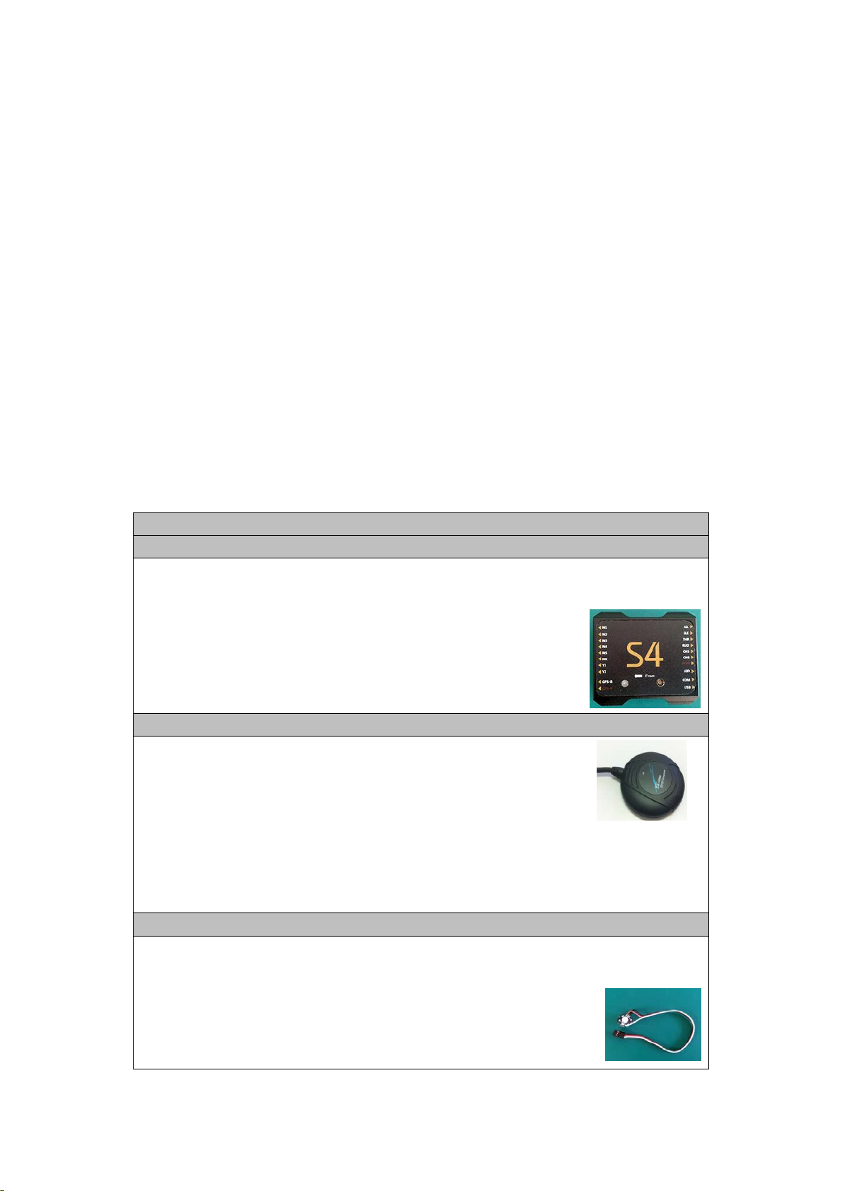
■Maincontrollerx1
TheMC(MainController)withitsintegralInertialMeasurementUnit(IMU)combinesandcommunicates
withtheothermodulesandexternalelectronicdevicestocarryoutitsfunctionasacompleteautopilot
system.
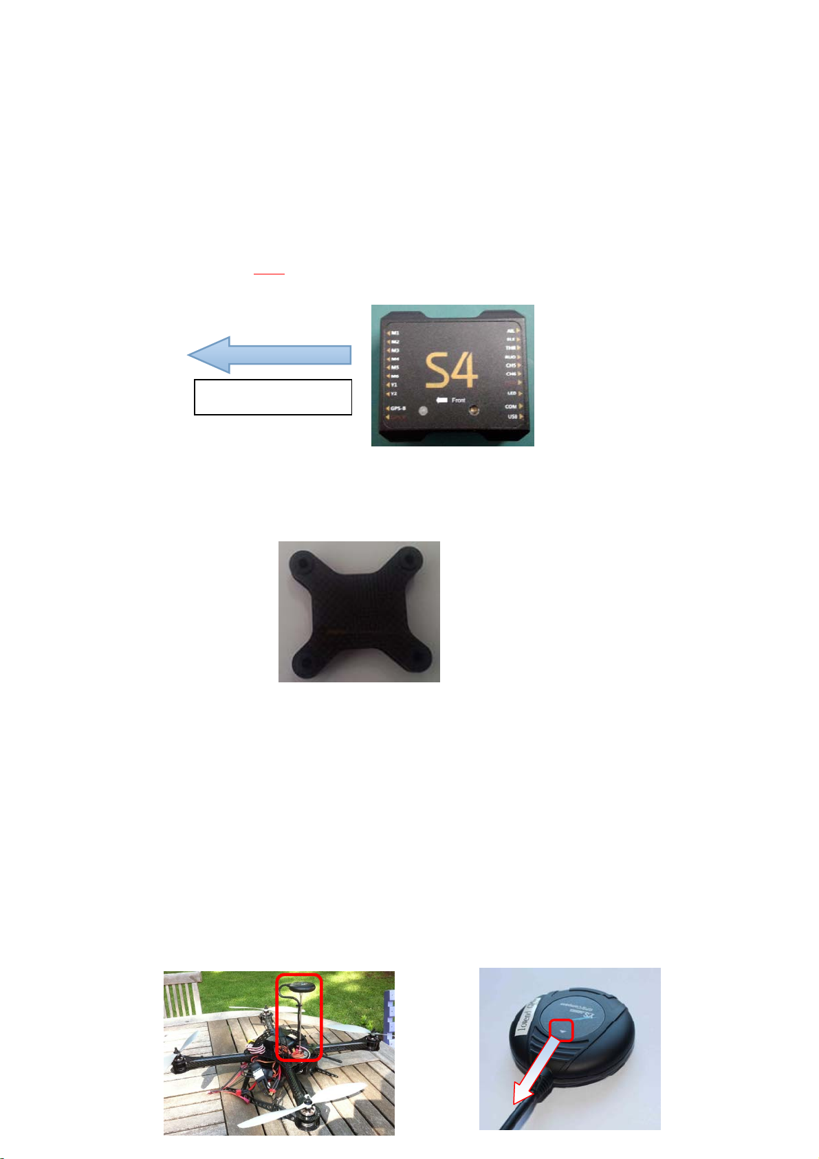
■GPS+COMPASSx1
TheGPS/Compassmoduleisforsensingtheorientationoftheaircraftbyreadingits
positionanddirection
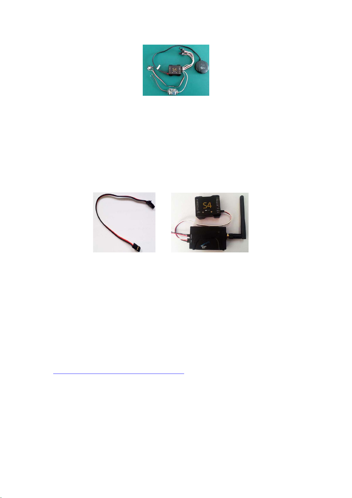
■LEDx1
TheLEDindicatesthecurrentflightstatusofthecraft..Thelightshowsinformationsuchasflightmode,
numberofsatellitesinviewandbatteryused.

YS-S4 Multi-rotor Autopilot User Manual V1.4
5
■PowerModulex1
Suppliesregulatedpowerfortheautopilot
■GPSBracketx1
TheGPS+COMPASSissensitivetomagneticinterference.ThisbracketisusedtomounttheGPSmodule
wherenecessaryandtokeepitfarawayfromEMIsources.
■WarrantyInformationCardX1
ThisprovidesProductSerialNo.,PurchaseDate.PleasefillouttherelevantinformationandreturntoZero
UAVtoregisteryourproductwarranty.
Softwareavailableonwebsitefordownload:
□GCSSowareforAndroidSystem
□GSSoftwareforPCWindowsXP/7/SP3system
□FirmwareUpgradeSowareonPC.
□Firmwareupdatingassistant.
3. Functions
1) Supportedmultirotorlayouts:
QuadX4,Quad+4,HexaX6,Hexa+6.
2) Fourworkingmodes:
i. Manualflightstabilisation
ii. Manualaltitudehold
iii. Autohover
iv. Returnhomeandland.
3) Standardsafetyfeatureswhentheaircraftlosescontrol:
Failsafe:autoreturn‐homeandauto‐landing,failsafe:land,failsafe:auto‐hover
4) TheLEDindicatestheautopilot’scurrentstatus.(GPSlock,lowvoltagealert,
Attitudeerror,etc.)
5) Controlmethod:RCTransmitter
6) ParameteradjustmentbyAndroidPhone,TabletorPC
7) Firmwareupgradesupport:UpgradefirmwareviaUSBcabletoCOMport.
8) Receiversupport:AllPPMreceivers
9) Gimbalsupport:Servogimbal
YS-S4 Multi-rotor Autopilot User Manual V1.4
6
4. Installation
4.1YS‐S4ModuleInstallation
1) TheYS‐S4Moduleshouldbeplacedlevelonthemainbodyoftheaircraft.
2) ForbestresultsinstallattheCenterofGravity(CoG)oftheaircraft.
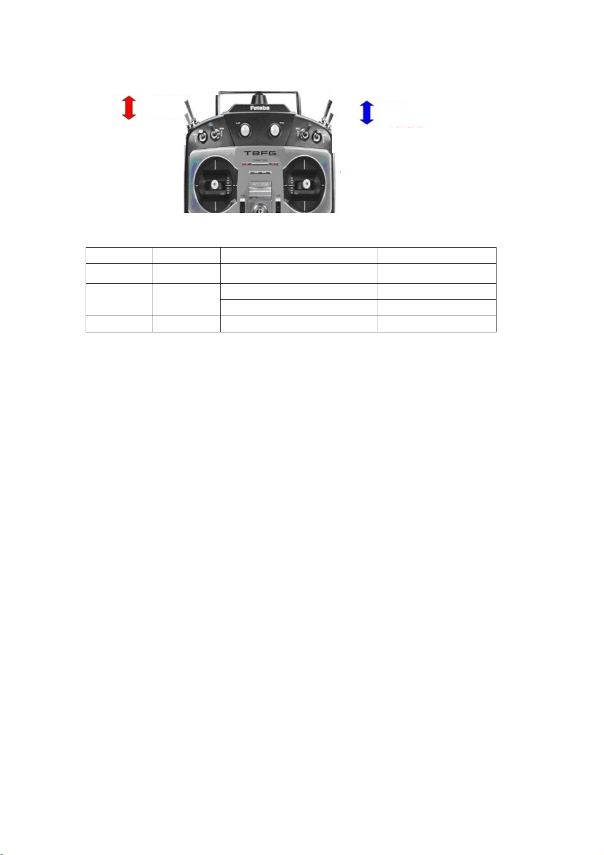
3) The“FrontArrow”MUSTpointtowardstheheadoftheaircraft:
IMPORTANT:
TheYS‐S4willadapttomostaircrafttypeswithoutinnerdampening.Itmaynotadaptsatisfactorilytolarger
aircraftinwhichcasetheYS‐S4shouldbemountedontheoptionaldampeningstructureshownbelowand
availablefromZeroUAV.
YS‐S4dampeningstructure
4.2GPSModuleInstallation
1) Ensurethatthestickerfacesupandthearrowpointstowardstheheadoftheaircraft.Otherwisetheaircraft
mayflyincircleswheninauto‐hovermode.
2) TheGPSmoduleshouldbeinstalledonalevelGPSstand,mountedhigherthantheelectricalcomponentson
theaircraft.Thisensuresminimalmagneticfieldeffectfromtheotheron‐boardcomponents,suchaspower
cables,transmitters,motors,ESCsandcamera.
Arrowtowards
aircrafthead
Towards aircraft nose

YS-S4 Multi-rotor Autopilot User Manual V1.4
7
5. Connections
5.1
Assembly
IMPORTANT
a. Ensuretheoriginalfactorysuppliedpowermoduleisused.Themanufacturerholdsnoresponsibilityifthe
S4isburntoutbyusinganyotherpowermodule.
b. ThePowersupplymoduleandtheWI‐FImodulemustconnecttoa3S‐6SLIPObattery.Thevoltagerange
wouldthereforebe10.8V‐25.5V.Normallythiswouldbeyourmainflightbattery.
c. TheRCreceiver(PPMsupported)ispowereddirectlyfromtheMC.DONOTpowerthereceiverwithany
additionalmoduleortheYS‐S4unitmaybeburntout.
d. MotorsandESCs(EspeciallywhenseveralESCsaretogether),cancauseseriousmagneticinterferenceso
theGPSmodulemustbeasfarawayfromtheseaspossible.Anon‐ferricbracketmustbeusedwiththearrowon
theGPSfacingforward.Alsothebatteryconnectioncarriesahighcurrentandmayresultinastrongmagnetic
field.KeepthebatterywiresasfarawayaspossiblefromtheGPSmoduleotherwiseyouraircraftmayflyin
circles!
e. Ifusingaservogimbal,makesuretheSERVOsarepoweredseparately.
f. WHITEcorewireisalwaysthesignalline,theREDcorewireispositive;theBLACKcorewireisground(0v).

YS-S4 Multi-rotor Autopilot User Manual V1.4
8
g. OnlytheUSBinterfacecanbeusedforParameterSettingandFirmwareUpgrade.TheCOMportisalsoan
interfacetoconnecttoaWI‐FImodule.
h. TheYS‐S4DOESNOTsupportESCcalibrationTheESCsshouldbecalibratedindependentlyreferringtothe
manufacturersuppliedESCmanual.ItisagoodideatodisabletheESClow‐voltagecutout.WithmostESCsall
youneeddoisconfigurethemtoNiMH.
5.2HowtoConnecttheModules
1)Connectthepowersupplymodule
Asshownbelow,one3‐corecableisusedtoconnecttheS4tothepowerunit,theWHITE‐coreisup,the
RED‐coreisinthemiddleandtheBLACK‐coreisbelow.
TheREDandBLACKbarewiresshouldtobesolderedtothePositiveandNegativepoleofthebatterypack
connector(3S‐6SLipo).
2) ConnecttheLEDmodule
TheLEDmoduleshouldbeconnectedtotheLEDinterfaceoftheS4maincontrollerasshown.
3)ConnecttheGPSmodule
TheGPSmodulehasredandblackends;theREDendisconnectedtotheS4GPS‐Rinterface,andtheblackendto
theGPS‐Binterface.Thesideoftheslotfacesup.
4)Connectthereceiver
YS-S4 Multi-rotor Autopilot User Manual V1.4
9
Thereceivershouldbeconnectedasfollows:theWHITEwire(signal)isup,theREDwire(positive)isinthe
middle,andtheBLACKwire(ground)isatthebottom.TheESCwiresshouldbeconnectedinthesamewaybut
NB:IfyourESCshaveaBEC(supplyvoltageviaabatteryequivalencecircuit)thenyoumustremovetheredwire
fromeach.IfyouarenotsureabouttheBEC,removetheredwireanyway!
5)ConnecttheWI‐FIModule(extendedconnection)
TheWI‐FIdatacableisa3‐corecable,connecttheendwhichhasthelocktotheWI‐FImoduleandconnectthe
otherendtotheCOMinterfaceontheYS‐S4(whitewireisup,redisinthemiddle,blackisbelow).TheWI‐FI
moduleshouldbepoweredseparately;powersupplyrangeis3s‐6sLipo.
6. ConfigurationbeforeFlying
6.1
InstallPhoneGroundControlSoftware(GCS)
TousethePhoneGCS,youmustpurchasetheoptionalWI‐FImodule.Downloadthe“Phone‐GCS
Software‐YSS4V2”fromourofficialwebsite
http://www.zerouav.com/en/service/Download/Software/
TheAppmustbeinstalledtotheMobile‐phonememorycard.Itcanbeinstalledautomaticallybyselecting
INSTALLontheAPKfileonceinthefilemanager.

YS-S4 Multi-rotor Autopilot User Manual V1.4
10
S4V2‐GCS
StarttheGCS;youwillseetheserialnumberandfirmwareversionfortheautopilotontheinterfaceoncethe
datahasconnected.
AfterconnectingyourWI‐FItotheGCSsuccessfully,youcanalsoseethereal‐timeupdateddataonthe"Data"
Page.
6.2 TXSetup
1) Selectfixedwingmodelonyourtransmitter.Removeanychannelmixing.
2) FUTABARadio:AllchannelsshouldbeNormal(notreversed).
3) JR,JTm,SpektrumandWFLYRadios:Reverseallchannels.
Step1:SelectTwoSwitches
Ensureyourradiohastwosetsoftwo‐wayswitches.ProgrammeCH5andCH6totheseswitchestocontrolthe
flightmodes:
YS-S4 Multi-rotor Autopilot User Manual V1.4
11
Adjustyourtwo‐wayswitchendpointstocontroltheflightmodes:
CH5PositionCH6PositionGPSStatusWorkingMode
Position1Position1XManualStabilization
Position2Position1GPSNoLockManualAltitudeHold
GPSLock(above5satellites)AutoHover
XPosition2GPSLock(above5satellites)ReturnandLand
IMPORTANT:
ReturnandLandmodealwaystakespriority.InanymodetheautopilotwillperformtheReturnandLand
operationifCH6isswitchedtoposition2.
Step2Fail‐SafeSetup(F/S)
Thereare2waysofsettingupF/S:defaultmodeandoptionalmode
1)DefaultF/Smode
CheckwithyourRadiomanualonhowtosettheReceiverfailsafe.EnsurethatwhenyouturnOFFyourradio,
yourfailsafesettingsareasfollows:
CH5settoposition2
CH6settoposition2
THRset50%(mid‐point)
DefaultF/SonlyhasReturnandLandmodewhichmeanstheYS‐S4willcommandtheaircrafttoReturnandLand
automaticallyifthecommunicationbetweentheTXandtheautopilotisdisconnected.
2)OptionalF/SSetup
IMPORTANT
1) ThisonlyappliestoFUTABAtransmitters.
2) “OptionalF/S”isnotrecommendedforbeginnersbecausethesettingprocedureisverycomplicated.
EnsurethatwhenyouturnOFFyourradio,yourfailsafesettingsareasfollows:
CH5issettoposition2
CH6issetto50%(mid‐point)
CH5Position1—ManualStabilizationMode
CH5Position2—AutoMode
CH6Position1—Neutral
CH6Position2 —ReturnandLand

YS-S4 Multi-rotor Autopilot User Manual V1.4
12
THRissetto50%(mid‐point)
CheckwithyourRadiomanualonhowtosettheReceiverfailsafe.
HereyoucanchooseanyofthefollowingF/Smodes:AutoRTHandLand;AutoLandandAutoHover.Nowthe
YS‐S4autopilotwillcontroltheaircraftaccordingthepre‐programmedF/SmodeiftheaircraftlosestheTXsignal.
(setthisuponthePCsoftwareunder“FailSafe”options)
PleaserefertothisvideoforhelpsettingupyourTX:
http://www.tudou.com/programs/view/e1ai526Mbt4/
6.3 ParameterSetup
YS‐S4Parametersettingcanbeachievedusingamobilephoneortablet(mustbeconnectedtoWI‐FI)orbyusing
aPCtoadjusttheparameters.
6.3.1 PCParameterAdjustment
Pleasedownloadthespecial“PC‐ParameterSetupSoftware”fromtheZerowebsitebeforeparameter
configuration.
IMPORTANT
1) “PC‐ParameterSetupSoftware”isalsothefirmwareupgradetool;
2) S4willchoosedifferentworkingmodesifthesequenceusedinpowering‐onisdifferent:
IfyoupowertheS4firstandthenconnecttheUSBcableyouwillbein“ParameterSetup”Mode.
IfyouconnecttheUSBcablefirstandthenpowerontheS4thenyouarein“FirmwareUpgrade”Mode.
PLEASENOTETHEFOLLOWINGWHENSETTINGUPANDINSTALLINGTHES4:
Whenthecraftisontheground,powertheTXfirstandthenpowertheS4.PleaseMAKESUREpropellersare
removedbeforeconnectingthebatterytopreventinjuryfromthemotorsstartingunexpectedly.
a. PowertheYS‐S4firstandthen2secondslaterconnecttheYS‐S4moduletoyourPCviatheUSB
interface.MAKESUREtheTHRstickisatthebottom.ConnecttheminiUSBcable.
b. Selectandopensoftware“S4‐GCS‐USB.exe”,press“OpenUSB”andpressthe‘Read’button(Ifthis
failstryseveraltimes)todownloadyourYS‐S4modulecurrentaircraftconfiguration.
c. Press‘Save’button(Ifthisfailstryseveraltimes)touploadthenewestparameterstotheYS‐S4ifthe
parametershavebeenchanged.
d. Torestorethedefaultparameters,pushTHRsticktobottomandpress‘Default’button.
e. TheS4V2defaultparametersareshownbelow:

YS-S4 Multi-rotor Autopilot User Manual V1.4
13
RollsensitivityandPitchsensitivitywouldaffectthedegreeofcommandresponseinflight(Defaultvalueis45,
range0‐255),MotionCompensationcanincreasestabilitybutwoulddecreasethesensitivity(Defaultvalueis20,
range0‐255).
Set u
p
the
m
aximu
m
fli
g
ht s
p
eed.
Set up the Maximum rate of climb and descent.
Enter the voltage per cell required to activate a low voltage alert, for a
Li
p
o batter
y
this would be normall
y
b
e3.65v。
Roll/Pitch sensitivity is used to adjust the compensation angle of the PTZ
data for your Gimbal. Your can compensate high or low for aircraft
movement within a range from -127 to 127 (Note: You can enter a negative
value to reverse the direction of compensation).
The autopilot can calculate the low voltage alert according to the number of
cells entered. If your phone vibrates once every 2 seconds it is a reminder
that the power is getting low. When it vibrates continuously it means the
power is getting very low and you should land at once.
Enter this to match the frequency of your gimbal servos. 50Hz, 250Hz,
333Hz and 400Hz servos are supported.

YS-S4 Multi-rotor Autopilot User Manual V1.4
14
6.3.2 PhoneParameterAdjustment
Pressthe“Parameter”optionontheGCSwhentheWI‐FImoduleisconnectedanddataisbeingcommunicated.
Togetthecurrentparametersoftheaircraft,clicktheGetbuttontogetthecurrentparameters(Clickseveral
timesifitfails).
AfterchanginganyparametersettingsawayfromthecurrentsettingsyoumustclicktheSavebutton(clickseveral
timesifitfails),andtherevisedparameterstotheautopilotwillbesaved.
6.4 TXCalibration
TheremotecalibrationoftheYS‐S4canbeachievedintwoways:mobilephone(mustbeconnectedtotheWI‐FI)
orPCcalibration.
6.4.1 TransmitterchannelcalibrationbyPC
Step1:Selectthecorrectsticklayout
Enter your aircraft type.
The maximum height and distance allowed can be specified. The
maximum is 1500 meters, min 10 meters.
Set up Fail/Safe mode(Auto RTH and Land, Auto Land and Auto Hover are the
options)

YS-S4 Multi-rotor Autopilot User Manual V1.4
15
InthePCGCSselectthe"StickLayout"drop‐downmenu.The“HandMode”isyourtransmittermode(Mode1,
Mode2,Mode3etc.)
SelectthemodeaccordingtoyourpreferenceandthesticklayoutofyourTX.
Step2:Calibratethesticks
The‘AdjustTransmitter’windowwillappearonthePCGCS.Click‘OK’andmoveyourtransmitterstickwithin5
Secondstotheirmaximumpositionsasshowninthediagram:
Step3:Checkthatthestickdirectionasdepictedonthescreenmatchestheactualdirectionofmovementof
yoursticks.

YS-S4 Multi-rotor Autopilot User Manual V1.4
16
CheckthatthedisplayofeachstickshowsthatTXiscalibratedwell.Thisscreendisplaysthepositionofthesticks.
OntheleftistheRudderandElevator(Mode1depicted).OntherightistheaileronandTHRstick(Mode1
depicted).
WhenbothsticksareinthemiddlepositiontheyareshownasGREEN,anyotherpositionshowsREDexceptfor
whenthethrottlestickisatthebottomwhenitshowsasYELLOW.Whenthethrottleisinhoverposition
(normallyclosetothemiddleposition)itshowsGREEN,otherflyingstatusshowsRED.
6.4.2 TXCalibrationbyPhone
Step1Selectthecorrectsticklayout(Mode1,Mode2,Mode3etc.)
1) Clickthemenubuttononyourphonethenselect"Set”(seebelow)
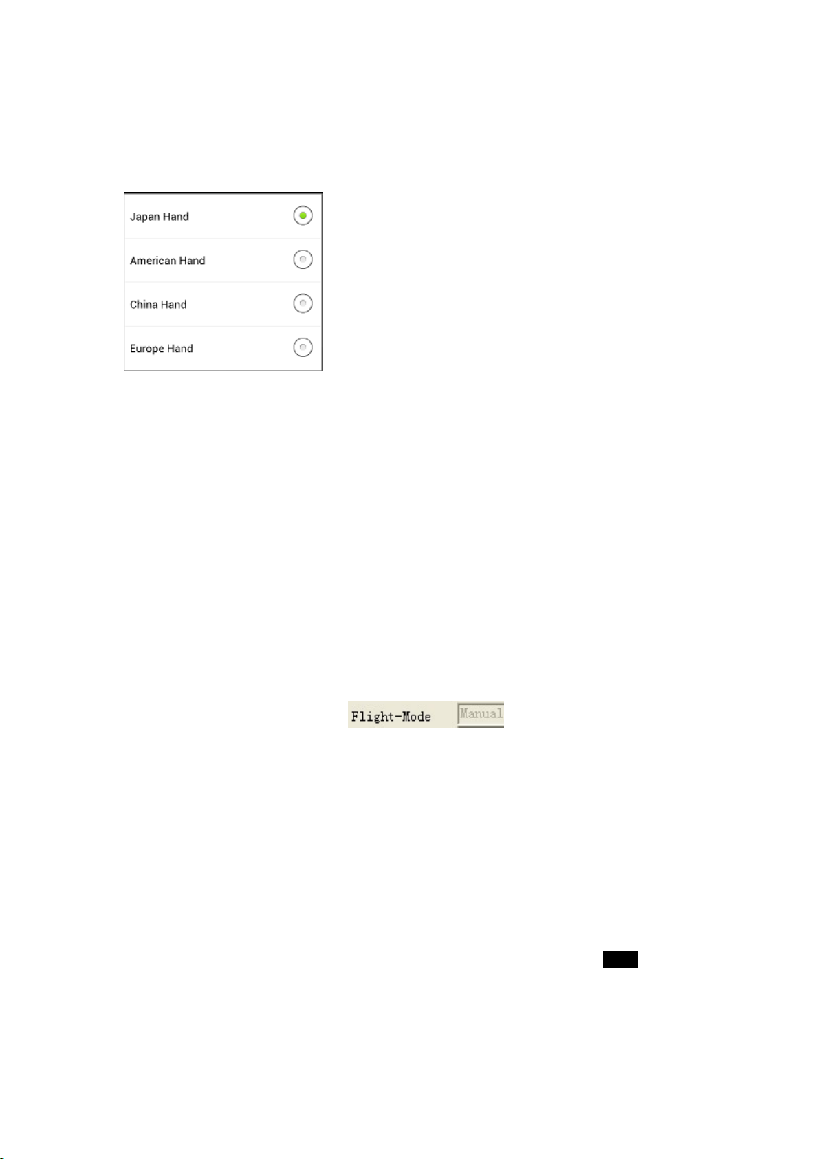
2) Inthe"Set"boxwhichopensselectthe"HandMode"drop‐downmenu.The“HandMode”isyour
transmittermode(Mode1,Mode2,Mode3etc.)
YS-S4 Multi-rotor Autopilot User Manual V1.4
17
3) Selectyourownoperationstyleinthehandmodemenu.Theillustrationshows“JapanHand”whichis
Mode1.
Step2Calibratethesticks
Clickthebutton“AdjustTransmitter”onGCS“Data”andclick"OK"inthedialogbox.Movebothstickstotheir
endpointsinacircularmotionwithin5Seconds.Theautopilotwillstorethemaximumandminimumendpoints
andalsothemidpointsofbothsticks.
6.5 Fail/SafeChecking
Step1CheckthatFlightModeschangeonTXcommand:
1) CheckFlightModesviatheConfigurationsoftware‘FlightMode’:
AssumingyourGPSmoduleisconnected;checkwhetherswitchingbetweenallworkingmodesisworking
normally.
Forexample:PlaceCH5atposition1andCH6atposition1,thePCGCS"data"pageshouldshowyourTXstatusas
"Manual",ChangeCH5toposition2forAutoHoverandsoon.Ifflightmodedoesnotchangewhenyoutoggle
theswitchespleasecheckyourhardwareconnectionsorRCTransmittersetup.
Step2:FailSafe(F/S)Checking
1) HowtocheckdefaultF/S
SWITCHOFFtheRCTransmitterwhilsttheautopilotisstillpoweredon;the‘Flight‐Mode’shouldswitchto
display"ReturnandLand",thethrottlestickindicatorshouldbeinthemiddleanddisplayedinGREEN.Ifitdoes
not,pleasesetupthefail‐safe(F/S)again.ItisstronglyrecommendedtousethedefaultF/S.
2) HowtocheckoptionalF/S

YS-S4 Multi-rotor Autopilot User Manual V1.4
18
SWITCHOFFtheRCTransmitterwhilsttheautopilotisstillpoweredon,the‘FlightMode’shouldswitchtodisplay
"ReturnandLand",“Land”or“Autohover”(theseoptionsarethechosenF/SsettingsfromyourPCGCS)the
throttlestickindicatorshouldbeinthemiddleanddisplayedinGREEN.Ifnot,pleasesetupthefail‐safe(F/S)
again.
7. AdjustmentOutdoors
7.1 GPS/CompassCalibration
WhenusingtheS4V2autopilotforthefirsttime,theGPS/COMPASSmustbecalibratedbeforearmingthe
motors.
IMPORTANT:
(1)Compasscalibrationdoesnotneedtobedoneeverytimeyouflybutshouldbedonewhencomponentsare
movedoriftheaircraftfliesinunexpectedways,likeincircles,forexample.
(2)ALWAYScarryoutthiscalibrationoutdoors,farawayfrommetallicobjects(cars,radiotowers,powerlines
etc.).
Therearetwowaystocalibratethecompass:bySmartphone(withWI‐FImodule)orbyPC.Thereare3stepsto
follow:
1.Levelcalibration
2.Verticalcalibration
3.SaveGPS/COMPASSdata.
YS-S4 Multi-rotor Autopilot User Manual V1.4
19
7.1.1 CompassalignmentwithoutSmartphone.
Step1
MoveCH5andCH6onthetransmittertoPosition1andmakesureChannel5&6switchesareinposition1
(ManualMode).Levelyourmulticopter.FlipCH5switchthreetimesquicklybetweenPosition1andPosition
2(1>2>1>2>1>2>1)andtheLEDturnsgreen.YouhaveenteredHorizontalCalibration.
Step2
Rotatethemulticoptercounterclockwise(orclockwise)threetimes.ENSUREthattheGREENLEDremainsON
duringthisprocedure.IfitturnsOFF,itmeanstheaircraftisnothorizontal.AdjustthepositionuntiltheGREEN
LEDisbackONandcontinuewiththerotationandputthemulticopterlevelagain.
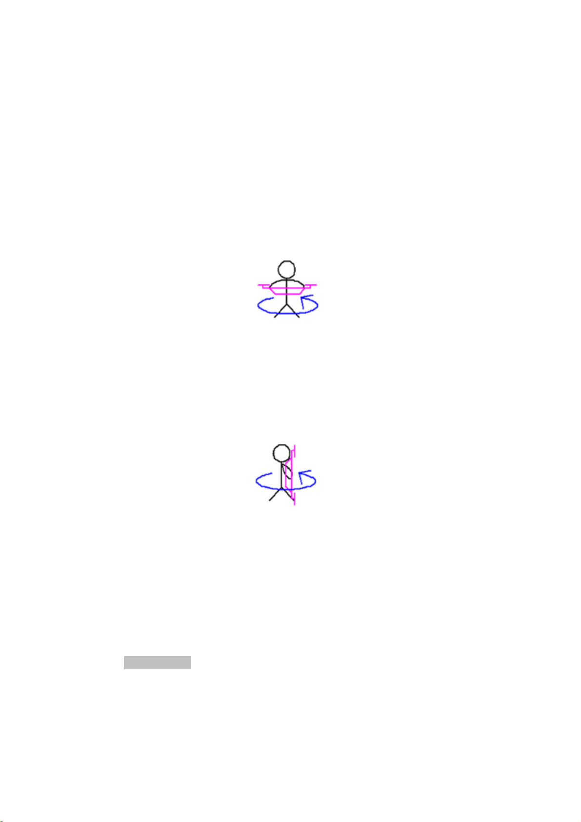
Step3
FlipCH5switchthreetimes(1>2>1>2>1>2>1)andtheLEDturnsoff.YouhaveenteredVerticalCalibration.
HoldthemulticopternosedownandtheLEDturnsgreen.
Rotatethemulticopter3timescounterclockwiseasshownbelow,alwayskeepingtheaircraftnosedown.Ensure
theGREENLEDremainsONduringtheturn.IftheLEDturnsOFF,adjusttheattitudeofthemulticopteruntilthe
GREENLEDisbackONandcontinuewiththerotationandputthemulticopterlevelagainwhenfinishedthe
rotation.TheLEDturnsoff.
Step4
FlipCH5switchthreetimes(1>2>1>2>1>2>1)quicklyandtheLEDturnsgreen.WaituntiltheLEDturnsoff.
Thatindicatesthecompasscalibrationisdone.
7.1.2 CompassalignmentusingSmartphone
Step1
Clickthe“MagneticCompass”buttononthePhoneGCS"Data"Page:

YS-S4 Multi-rotor Autopilot User Manual V1.4
20
Step2
Select"HorizontalAlignment"inthedialogbox,andthenclick"OK"buttontostartlevelcalibration.Ifyoudon't
wanttokeepcalibratingselect"Cancel"andconfirm“OK”.
Step3
Levelyouraircraftandcarefullyturnaroundhorizontallythreetimes.ENSUREthattheGREENLEDlightremains
ONduringthisprocedure.IfitturnsOFF,thatmeanstheaircraftisnothorizontal.Adjustthepositionuntilthe
GREENLEDisbackONandcontinuewiththerotation.
Step4
Select"VerticalAlignment"inthedialogbox,andclick"OK"buttontostarttheverticalcalibration.Ifyoudon't
wanttokeeponcalibratingselect"Cancel"andconfirm“OK”.
Step5
Carefullyrotatetheaircraft3timesasshownbelow,alwayskeepingtheaircraftnosedown.EnsuretheGREEN
LEDremainsONthroughouttheturn.IftheLEDturnsOFF,adjustpositionuntiltheGREENLEDisbackONand
continuewiththerotation
Table of contents


