ZGC IxL-II 10.20 User manual

Low Voltage Servo Drive Manuals
www.zgcmotors.com/
Low Voltage Servo Drive Manuals

Low Voltage Servo Drive Manuals
www.zgcmotors.com/
Notice before using
●The power supply voltage used by the low voltage servo driver is 20-90v dc.
Please install 20-90v DC power supply for the servo system. The specific voltage depends on the model.
It is strictly forbidden to connect the servo motor directly to the power grid.
●It is forbidden to connect the servo motor directly to the power grid, which is easy to damage the servo
motor. The servo motor cannot rotate without the support of the servo driver.
●Do not plug in or pull out the connector on the driver after power on. It is easy to damage the internal circuit
of the driver and the motor encoder by inserting or pulling the connector when it is charged eletricity.
●Please plug or pull the connector after the power is cut off.
Check the servo system after power off.
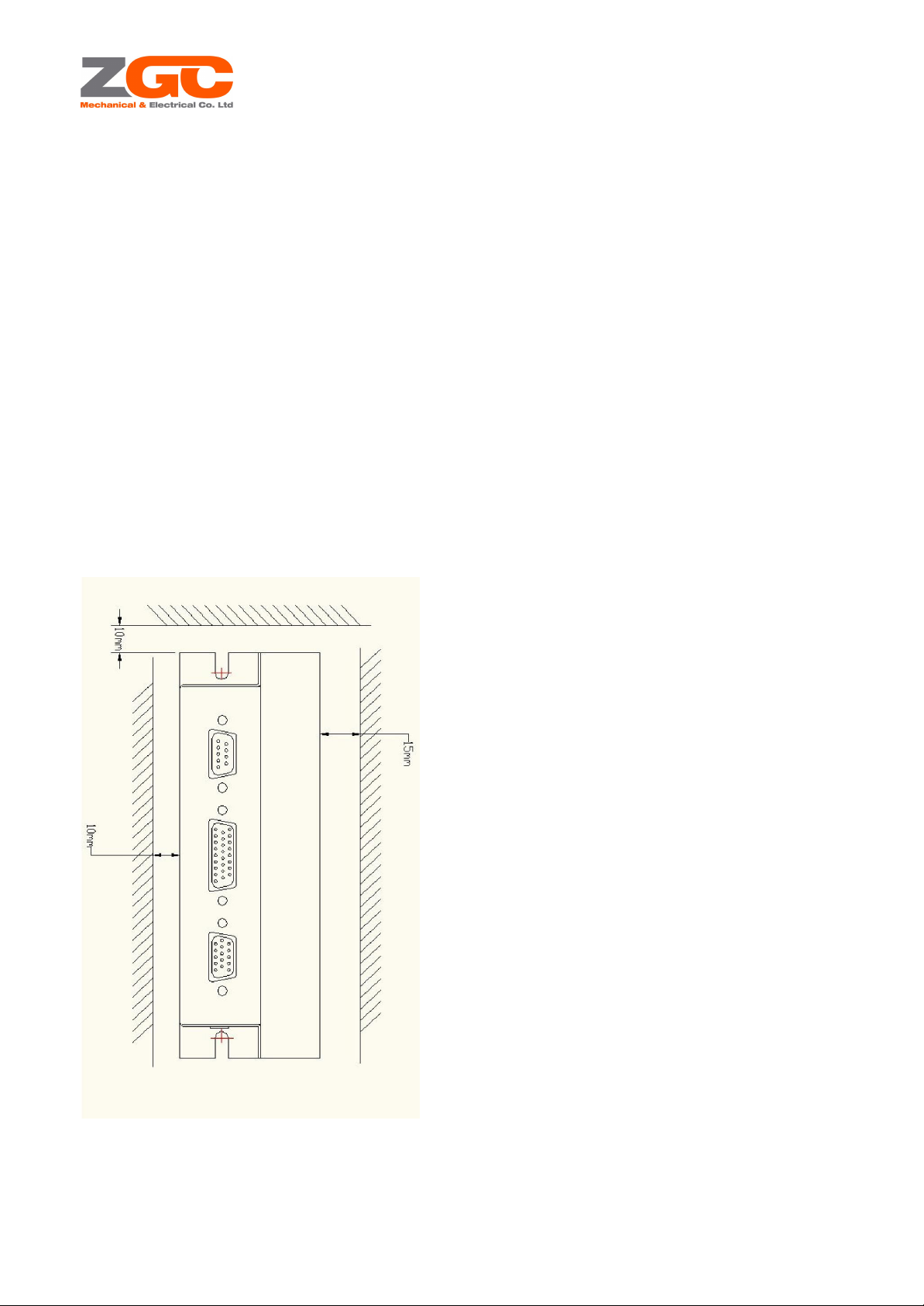
The installation interval between the servo driver and other equipment in the cabinet should be kept at more
than 10 mm.
The servo driver is easy to heat, so the installation layout that is near to heat source should be selected as
far as possible. The horizontal spacing between the servo driver and other equipment in the electric cabinet
should be more than 10 mm, and the longitudinal spacing should be more than 50 mm. The installation
environment should not be affected by condensation, vibration and impact.
Anti interference processing and grounding.
The interference on the signal line is easy to cause mechanical vibration and abnormal operation. The
following regulations must be strictly observed:
1. Separate the strong current cable and weak current cable.
2. Shorten the cable length as much as possible.
3. The installation of servo motor and driver shall adopt single point grounding, and the grounding
impedance shall be less than 10 Ω.
4. It is forbidden to use power input interference filter between servo motor and driver.
Leakage protector, quick response leakage protector should be used.
Use the quick response leakage protector or the PWM inverter specified by the supplier for leakage
protection. It is strictly forbidden to use the delay leakage protector.
Avoid extreme adjustments or changes.
It is not suitable to adjust or change the parameters of the servo driver, otherwise it is easy to cause severe
mechanical vibration and unnecessary property loss.
Do not use the power on / off to run the servo motor directly.
Frequent on / off of the power supply will lead to the rapid aging of the internal components of the servo
driver and reduce the service life of the driver. The command signal should be used to control the operation
of the servo motor.

Low Voltage Servo Drive Manuals
www.zgcmotors.com/
1. Product specifications and installation
1.1 confirmation of product arrival
When unpacking, please confirm the following items carefully:
Whether there is damage during transportation?
Is the driver model consistent with your order requirements?
Are the accessories complete or the following devices are installed in the packing box?
Item name
Quantity
Driver
1
25 core signal interface terminal
1
15 core encoder interface terminal
1
6
New mx3.0 terminals and pins
1
Main circuit terminal block
1
Power off brake terminal block
1
Note: please contact our company immediately if you find any of it missing.
1. 2 driver model and specification
1.2.1 Series servo driver specifications

Low Voltage Servo Drive Manuals
www.zgcmotors.com/
Item name
IxL-II 10.20
IxL-II 20.40
IxL-II 30.60
Power input voltage
20-60/90V DC
Maximum power input current
20 Arms
40Arms
60 Arms
Rated power
480W/800W
960W/1600W
1400W/2100W
Heat capacity coefficient
720 J/C
Maximum speed < 100RPM
Continuous output current
10Arms
20Arms
30Arms
Maximum speed continuous
current at maximum speed
8Arms
17Arms
26Arms
Maximum Output current
20 Arms
40 Arms
60 Arms
Maximum output voltage
Vin * 0.95 VDC
PWM frequency
10 KHz
Rated power efficiency
97%
Dimensions
SIZE 1
SIZE2
Weight
0.72KG
0.8KG
Cooling
Nature cooling

Low Voltage Servo Drive Manuals
www.zgcmotors.com/
Item name
IxL-II 50.100
IxL-II 80.160
IxL-II 150.300
Power input voltage
2 0 - 6 0 / 9 0 V D C
Maximum power input current
100 Arms
160A
300A
Rated power
2400W/4000W
4000W/7000W
5500W/1 1kW
Heat capacity coefficient
720 J/C
Maximum speed < 100RPM
Continuous output current
50Arms
80Arms
1 50Arms
Maximum speed continuous
current
at maximum speed
45Arms
70Arms
130Arms
Maximum Output current
100 Arms
160 Arms
300 Arms
Maximum output voltage
Vin * 0.95 VDC
PWM frequency
10KHz
Rated power efficiency
97%
Dimensions
SIZE 3
SIZE 4
Weight
1.86KG
3.0KG
Cooling
Nature cooling

Low Voltage Servo Drive Manuals
www.zgcmotors.com/
1.3
Driver electrical characteristics
Item
Function
Control
control mode
Speed control (PV), torque control (PT), position control
(PP), IP, CSP, CSV, CST
Support motor
Permanent magnet synchronous motor, brushless DC motor,
brushless DC motor
Position control
accuracy
±1Pulse (16bits)
Speed control
accuracy
±0.05%
Control input and
output signal
Analogy input
Two analog inputs, - 10V - + 10V
Digital input
8-channel digital input, 12-30vdc
Digi tal out put
4 digital output, open collector output
communication
interface
RS-232/485
Standard Modbus Protocol
CanOpen
Standard CANopen protocol, cia301 / 402
EtherCAT
Standard COE protocol
Encoder interface
Encoder port E1
Incremental encoder, SSI / bissb / bissc absolute encoder,
NRZ Tamakawa absolute encoder, Hall signal position
feedback
indicator light
Working status display
Reflect the current working state of the driver and alarm
indication code
Environment
Place of use
Indoor, no direct sunlight, no dust, no corrosive gas, no
combustible gas, no oil mist, no water vapor, etc
Operating ambient
temperature
-When the temperature is between 20 ℃and 50 ℃, it can
be used with derating when the temperature is higher than
40 ℃
Altitude
The altitude of the place of use is lower than 1000m, and the
altitude of the place of use is higher than 1000m
humidity
Below 95% RH, no condensation
Vibration
Less than 0.5g (4.9M / S2), less than 10Hz
Storage temperature
-40℃—70℃
Strrucuture
Cool ing
Nature cooling
Protection level
IP20
Installation method
Wall mounted

Low Voltage Servo Drive Manuals
www.zgcmotors.com/
1.3.1 attenuation of ambient temperature and maximum continuous output current the maximum continuous
output current of the driver will decrease with the increase of ambient temperature,
Users should consider reducing the maximum continuous output current of the driver. The variation of
specific ambient temperature and maximum continuous output current is shown in the figure.
1.4
Drive Size1 dimensions
Dimension size 1

Low Voltage Servo Drive Manuals
www.zgcmotors.com/
Dimension size 2
Dimension size 3

Low Voltage Servo Drive Manuals
www.zgcmotors.com/
Dimension size 4
1.5 Installation precautions
The servo driver is a base mounted servo driver. If the installation is not correct, there may be faults. Please
install correctly according to the following precautions.
Please install it in a well ventilated place. In order to facilitate the heat dissipation of the drive, the vertical
installation mode should be generally adopted;
The allowable ambient temperature of the driver is 0 ℃- 50 ℃, but if the ambient temperature is higher

Low Voltage Servo Drive Manuals
www.zgcmotors.com/
than 40 ℃, the maximum continuous output current should be reduced by 20% for every 10 ℃increase,
and the ventilation and heat dissipation should be strengthened;
The humidity of the installation site should be lower than 95% without condensation;
It is not allowed to be installed in places with dust and metal powder;
It is not allowed to be installed in places with corrosive and explosive gas;
It is installed in the place where the vibration is less than 0.5g (4.9M / S2), and the vibration frequency is less
than 10Hz;
Install in a place without direct sunlight;
Using under altitude is lower than 1000m, when it is higher than 1000m, the maximum continuous output
current of the driver should be reduced by 3% for every 100m increase.
(9) When the continuous operating current of Size1 / size2 driver exceeds 15a, size3 driver exceeds 30A
and size4 driver exceeds 50a, it is necessary to provide external heat sink or install the driver on the metal
shell, and the heat sink silica gel or heat pad should be coated between the driver and the shell
1.6
Installation of drive
The installation space requirements of Size1 / size2 driver are shown in the figure

Low Voltage Servo Drive Manuals
www.zgcmotors.com/
The installation space requirements of Size3 / size4 driver are shown in the figure
Note: the size3 / size4 driver needs external radiator or external shell for heat dissipation due to high current.
When installing, pay attention to installing external radiator, and apply heat dissipation silicone or paste heat
pad between the driver and external radiator

Low Voltage Servo Drive Manuals
www.zgcmotors.com/
When multiple controllers are installed in the mechanical device, they should be installed side by side and
equipped with air inlet, air outlet and special cooling fan.
The Size1 / size2 driver is shown in the figure
SIZE3/SIZE4:
Note: the size3 / size4 driver needs external radiator or external shell for heat dissipation due to high
current. When installing, pay attention to installing external radiator, and apply heat dissipation silicone or

Low Voltage Servo Drive Manuals
www.zgcmotors.com/
paste heat pad between the driver and external radiator.
2.Wiring
2.1 wiring precautions
2.1.1 Wiring safety precautions
Wiring must be carried out by qualified personnel, otherwise there is a risk of electric shock;
Please make sure that the input power supply is completely disconnected before wiring, otherwise there is
a risk of electric shock;
The grounding terminal of the controller must be reliably connected with the ground wire of the
corresponding device (the ground wire should use more than 2.5mm2 copper core wire, and the grounding
resistance should be less than 10 Ω), otherwise there is a risk of electric shock;
Do not short circuit between the lines, otherwise there is a risk of fire and damage to the equipment;
It is strictly forbidden to connect the input power to the output side of the driver, otherwise the equipment
may be damaged;
All wiring connections must be reliably and firmly connected, otherwise there is a risk of damage to the
equipment;
The power supply of the control panel terminal shall not be higher than the specified range (DC 22v-90v),
otherwise the equipment may be damaged;
The exposed part of the wire at each wiring connection must be wrapped with insulating tape, otherwise
there is a risk of short circuit and damage to the equipment; (9) after completing the wiring, please check
whether the wiring is correct.
2.1.2 Wiring electrical precautions
It is not suitable to pass the power line and signal line through the same pipe or bind them together. When
wiring, the power line and signal line should be separated by more than 10cm.
The signal line and encoder feedback line shall be twisted pair with overall shielding, and the shielding
layer shall be connected to the connector shell. Wiring length: the maximum length of command signal
input line is 3M, and the maximum length of encoder feedback line is 20m.
Even if the power supply is turned off, there may still be high voltage in the servo driver. Please check the
wiring or work after 5 minutes of turning off the power.
Please do not turn on or off the power frequently. If you need to turn on or off the power repeatedly, it
should be controlled below once a minute. There is a capacitor installed inside the servo driver, when the
power is turned on, a large charging current will flow (charging time is tens of milliseconds); therefore, if the
power is turned on / off frequently, the components inside the servo driver will accelerate aging.
2.1.3 Recommended specification table of wires for wiring.
Drive model
Main curcuit cable(mm2)
Note
IxL-II 1020
2
It is suggested that the
conductor for main circuit
using High temperature
resistant wire
IxL-II 2040
4

Low Voltage Servo Drive Manuals
www.zgcmotors.com/
IxL-II 3060
6
IxL-II 50100
10
IxL-II 80160
16
IxL-II 150300
25
2.2
Electrical wiring diagram
2.2.1 SIZE1
Model external terminal definition
2.2.2 SIZE2
Model external terminal definition

Low Voltage Servo Drive Manuals
www.zgcmotors.com/
2.2.3 SIZE3
Model external terminal definition
2.2.4 SIZE4
Model external terminal definition

Low Voltage Servo Drive Manuals
www.zgcmotors.com/
2.3 Main circuit terminal P1
SIZE1/2 Drive main circuit terminal:
PIN
Name
Function
Description
J1
PE
Ground wire
J2
VP+
Power supply positive
20-90VDC
J3
RP
Power supply negative
J4
C
Motor U-phase input / brush
positive
RED
J5
B
Motor V-phase input
YELLOW
J6
A
Motor w-phase input / brush
negative ground wire
BLUE
SIZE3/4 Drive main circuit terminal
PIN
Name
Function
Description
J1
VP+
Power supply positive
20-90VDC
J2
RP
Power supply negative
J3
C
Motor U-phase input / brush
positive
RED
J4
B
Motor V-phase input
YELLOW
J5
A
Motor w-phase input / brush
negative ground wire
BLUE
2.4 Brake holding / brake terminal P2
Pin
name
type
function
1
K(N.O)
Relay normally open
interface
When power failure braking is needed, connect
the power failure brake of motor
2
R(Com)
Relay common terminal
3
B(N.C)
Relay normally closed
interface
Note: the max imum be aring current of internal re lay is 2A. If th e co nti nuous current is
grea ter th an 2a, plea se use exte rnal relay to transfe r, oth erwise there is a risk of damag e
to inte rnal rela y.

Low Voltage Servo Drive Manuals
www.zgcmotors.com/
2.5 Control signal terminal U1
Pin
name
type
function
01
IO_COM+
IO Input power
Input common
02
USRC _DI1
Digital input
Servo ON,Out DI effective
03
USRC _ AI1 _N
Analog input negative
Torque / speed limit input
12
USRC_AI1_P
Analog input positive
04
ORD_PUL_L
Pulse input interface
Command pulse signal input,
Input current: > 10mA
05
ORD _ SIG _L
Pulse input interface
06
ORD _ PUS _ POW
Pulse input power
supply
07
ORD_SIG_H
Pulse input interface
13
ORD_PUL_H
Pulse input interface
08
USRC_DI3
Digital input
Alarm cleared, external Di active
09
USRC_DO3
Digital output
Servo alarm output,<50mA
10
USRC _AI0 _N
Analog input negative
Current reference input / speed reference
input
11
USRC_AI0_P
Analog input positive
14
USRC_DI2
Digital input
Positive direction drive inhibit input

Low Voltage Servo Drive Manuals
www.zgcmotors.com/
15
USRC_DI4
Digital input
Negative direction drive inhibit input
16
USRC_DI5
Digital input
Home origin signal, external Di is enabled
effectively
17
USRC_DO2
Digital output
Positioning end / speed reaching output,
< 50mA
18
USRC_DO4
Digital output
spare
19
USRC_DI7
Digital input
Motor stop quickly
20
GND_DIG
Digitally ground
21
USRC_DI8
Digital input
Start motor returns to zero, external Di is
effectively enabled
22
+15V _DIG
Power output
<100mA
23
MOTOR _PTC
Analog input
Motor temperature sensor positive
24
USRC_DI6
Digital input
Control mode switching
25
IO_COM-
IO output power
supply
Output common
26
USRC_DO1
Digital output
Servo ready for output, < 50mA
2.5.1 Digital Di wiring

Low Voltage Servo Drive Manuals
www.zgcmotors.com/
2.5.2 Digital DO Wiring
2.5.3 Analogy AI Wiring
+/-10V Connection mode of analog command:
0-10V Analog quantity + direction signal command wiring mode:

Low Voltage Servo Drive Manuals
www.zgcmotors.com/
2.5.4 Pulse input wiring
Differential pulse input wiring:
This manual suits for next models
2
Table of contents
Popular Servo Drive manuals by other brands

Fastech
Fastech S-SERVOII operating manual

Leadshine
Leadshine HBS Series Hardware installation manual

Omron
Omron G5 Series Startup guide

Rockwell Automation
Rockwell Automation Allen-Bradley Ultra3000 Migration guide

Technosoft
Technosoft iPOS4808 BX-CAT-STO Technical reference

Moons'
Moons' SSM23C user manual