ZGR VERSATILE RT User manual

Operation Manual
ZGR VERSATILE RT - 10 KVA
Online Three-phase UPS
www.zigor.com

ZGR VERSATILE RT - 10 KVA
Manual de operaciones
www.zigor.com
2
INDEX
1PRECAUTIONS.....................................................................................................................................................4
General precautions.....................................................................................................................................4
Storage precautions.....................................................................................................................................5
Environmental precautions...........................................................................................................................5
Precautions during transportation................................................................................................................6
Precautions on receiving the unit.................................................................................................................6
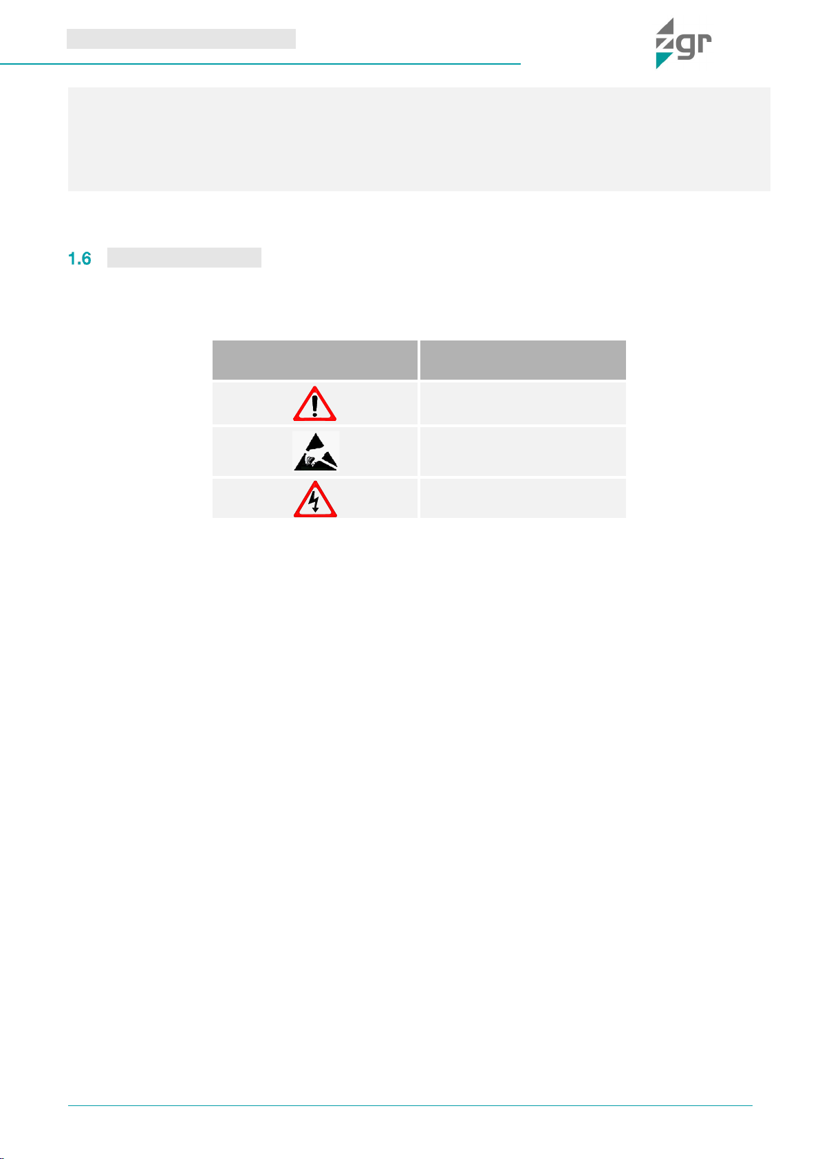
Symbol Description......................................................................................................................................7
2GENERAL DESCRIPTION.....................................................................................................................................8
Introduction ..................................................................................................................................................8
Main characteristics .....................................................................................................................................8
Construction of ZGR VERSATILE RT - 10 KVA ...........................................................................................9
3ZGR VERSATILE RT - 10 KVA OPERATION.......................................................................................................10
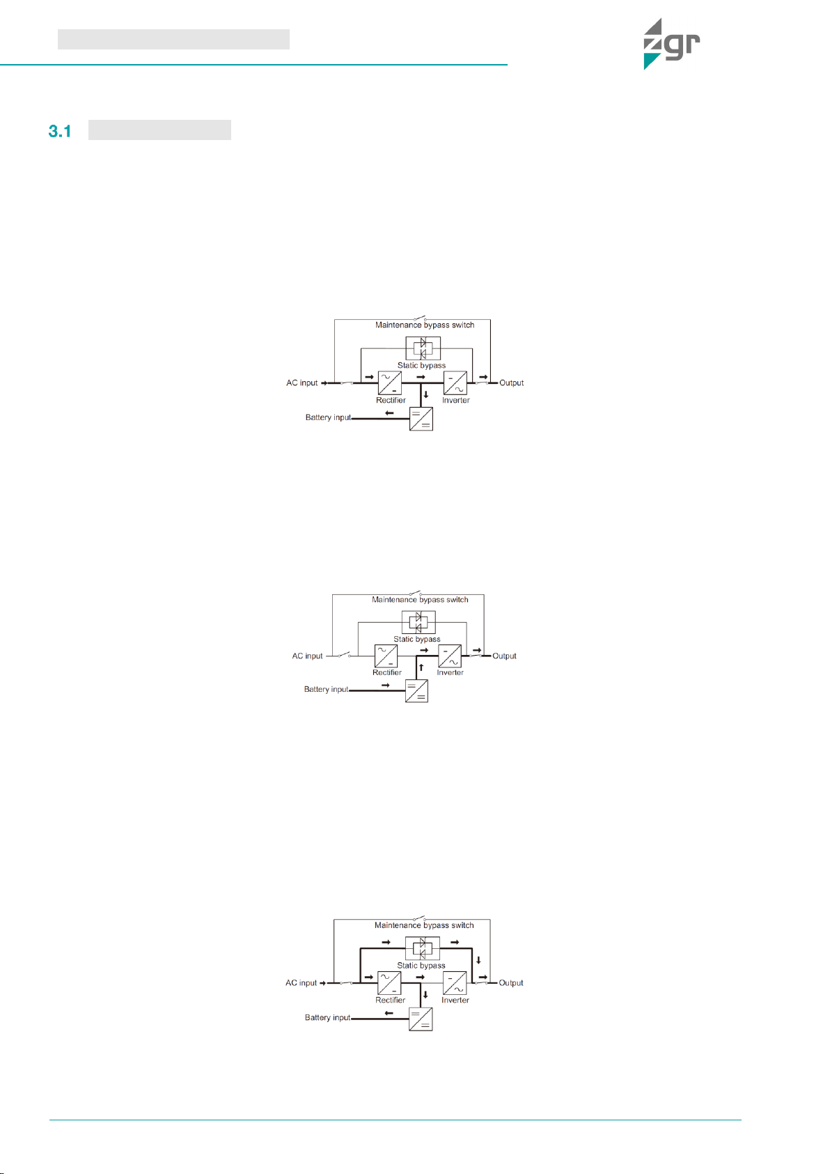
Operation Modes........................................................................................................................................10
3.1.1 Normal mode..........................................................................................................................................10
3.1.2 Battery mode (Stored Energy Mode) .....................................................................................................10
3.1.3 Bypass mode..........................................................................................................................................10
3.1.4 ECO Mode..............................................................................................................................................11
3.1.5 Parallel redundancy mode (system expansion) .....................................................................................11
Working Mode and transferring .................................................................................................................11
3.2.1 Transfer to bypass if overload................................................................................................................11
3.2.2 Normal mode to battery mode...............................................................................................................11
3.2.3 Go to bypass mode due to over temperature........................................................................................11
3.2.4 Output short circuit ................................................................................................................................12
3.2.5 Battery self-Test.....................................................................................................................................12
Turn on/off UPS..........................................................................................................................................12
3.3.1 Connecting with Utility ...........................................................................................................................12
3.3.2 Black (Cold) start procedure ..................................................................................................................13
3.3.3 Inverter Off..............................................................................................................................................13
3.3.4 Disconnecting with Utility.......................................................................................................................13
Control panel and monitorization...............................................................................................................14
3.4.1 LCD control panel ..................................................................................................................................14
3.4.2 Control panel menu................................................................................................................................14
3.4.3 Control panel interfaces.........................................................................................................................14
3.4.4 Status and operation modes..................................................................................................................20
Events and status list .................................................................................................................................20
4INSTALLATION ...................................................................................................................................................22
Unpack checking........................................................................................................................................22
Mechanical installation...............................................................................................................................22
Electrical installation...................................................................................................................................23
4.3.1 External Protective Devices ...................................................................................................................23
4.3.2 Power Cables connection......................................................................................................................23
4.3.3 Battery connection.................................................................................................................................26
Connection of the UPS communication cables.........................................................................................27

ZGR VERSATILE RT - 10 KVA
Manual de operaciones
www.zigor.com
3
4.4.1 USB communication port definition.......................................................................................................27
4.4.2 RS232 communication port definition ...................................................................................................27
UPS in parallel............................................................................................................................................28
4.5.1 Cabinet installation.................................................................................................................................28
4.5.2 Parallel cable installation........................................................................................................................29
4.5.3 Initial startup procedure for parallel system...........................................................................................29
5TROUBLESHOOTING.........................................................................................................................................30
Malfunctions of ZGR VERSATILE RT - 10 KVA.........................................................................................30
6MAINTENANCE ..................................................................................................................................................31
Battery maintenance..................................................................................................................................32
7TECHNICAL SPECIFICATIONS..........................................................................................................................33
8STANDARDS.......................................................................................................................................................35
9WARRANTY........................................................................................................................................................36
© 2022, ZIGOR
Reservados todos los derechos. No está permitida la reproducción total o parcial de este Manual de Operación, ni su
transmisión de ninguna forma o por cualquier medio, ya sea electrónico o mecánico, por fotocopia, registro u otro
procedimiento de almacenamiento o recuperación de información sin permiso del editor.
El contenido de este manual es exacto en el momento en que se procede a su impresión. Pero, con la intención de cumplir
con el compromiso de una política de continuos desarrollos y mejoras, el fabricante se reserva el derecho de cambiar las
especificaciones del producto, su funcionamiento, o los contenidos del Manual de Operación sin previo aviso.

ZGR VERSATILE RT - 10 KVA
Manual de operaciones
www.zigor.com
4
1PRECAUTIONS
General precautions
For your own safety and that of the unit, you must read and understand the instructions contained in this
document before starting work.
Keep these instructions in a place accessible to all the personnel who work with the unit so that they can be
consulted.
Only expert and duly authorised personnel may operate our units.
Danger warnings. When handling or accessing the interior of the ZGR VERSATILE RT - 10 KVA,
please remember that some parts may be live. Pay special attention to soldering points, printed
circuits, connecting terminals, relay contacts, etc. Before opening the equipment, disconnect the
voltage of all poles (both alternating and direct) and wait at least 5 minutes for the internal condensers
to discharge.
Arbitrary modifications are forbidden. The unit must not be subjected to any modification regarding its
construction or safety without express consent. Any modification will free ZIGOR of any responsibility
for any damage caused as a result of the modification. In particular, all repair work, soldering of printed circuit
boards and replacing of components, modules and printed circuit boards, without the express authorisation of
ZIGOR, is forbidden. Should spare parts be used, only ZIGOR original parts shall be utilised.
Use the unit for the purpose for which it was designed. The system supplied must be used only for the
purpose for which it was designed. Any other use is strictly forbidden. ZIGOR cannot accept responsibility for any
damage that might result from its use for any other purpose. In such cases, the user shall assume exclusive
responsibility for any risk. The use for which the unit was designed is defined in the documentation. The system
shall be exposed only to admissible environmental conditions. These are defined in the technical details provided
for the equipment.
ZIGOR accepts no responsibility for any inadequate, negligent or incorrect installation of the equipment.
Please follow the indications set out below to operate under conditions of complete safety:
•The System must be checked once the installation has been completed by a qualified technician and
before being put into operation. Should these indications not be adhered to, the warranty shall be
considered null and void.
•These units do not contain parts usable for other purposes by the user.
•Do not power up the device before a technician has checked it.
•Do not power the equipment before there has been a check by a technician.
•For safety reasons, please ground the UPS before turning it on.
•Given the risk of electric shock or burns, do not try to open the device.
•The unit does not contain any user repairable or replaceable elements. In the case of any malfunction or
problems operating the unit, please contact ZIGOR.
•Do not place the system near power magnets as this might cause a malfunction.
•Do not block or cover the ventilation grills in the housing.
•The ZGR VERSATILE RT - 10 KVA is designed in accordance with current Spanish legislation. Check
these regulations against those corresponding to the country in which the unit is to be installed and
against the most restrictive regulations of the electricity supplier.
•All user controls are accessible from the exterior.
•Work inside the cabinet should be undertaken only by qualified personnel who are familiar with the safety
measures to be applied and the specific technical characteristics of the unit.
WARNING
This supply equipment contains a lethal voltage. Comply with the instructions set out in this manual to avoid any
risk of electrical shock.

ZGR VERSATILE RT - 10 KVA
Manual de operaciones
www.zigor.com
5
•Even though all the safety systems are in place, before touching any working parts, you must check that
they are not live.
•This system has been designed for industrial use and not for domestic-commercial use.
•If any liquid is spilt accidentally on the System, disconnect this and consult ZIGOR personnel.
•During assembly work, start-up or maintenance, wear goggles to avoid any damage to your eyes due to
accidental electric arcing.
•Use only insulated tools.
•The unit must be protected against rain and excess humidity and installed in a clean atmosphere, without
inflammable liquids, gases or oxidising substances.
•The battery may pose a risk of electric shock or burns due to its high short circuit current.
•If the batteries lose electrolyte or are physically damaged, they must be placed in a container in resistant
to corrosive liquids (acids or alkaline according to the type of battery) and prepared in accordance with
local regulations.
•If the electrolyte comes into contact with the skin, the affected area must be washed immediately with
clean water.
•Only authorized personnel should repair or install the batteries.
•Should you have any problems with the contents of this manual, you must ask ZIGOR for assistance.
Storage precautions
The store where the material is kept must protect the material from the elements, risk of flooding or contact with
water.
The material shall be protected from any risk of overheating due to exposure to direct sunlight or through
windows.
The recommended storage temperature is from 15ºC to 25ºC. An increase of 10ºC can reduce the service life of
the battery by 50%. The recommended relative humidity is from 30% to 90%.
To avoid any risk of mechanical shock, do not stack the packages. These must be placed in accordance with the
silkscreen printed details on the boxes used for packaging.
Environmental precautions
WARNING
Any failure to respect these precautions may render the product warranty null and void.
Dispose of the packaging in an ecological way: ZIGOR, based on the exceptions detailed
in the First Additional Provision of Law 11/1997 on commercial or industrial packaging,
informs that the final holder of the waste of used containers and packaging, as responsible
for them, you must deliver them in appropriate conditions for reuse, to an authorized
recuperator, recycler or re-valuer.
The subsets of the system are recyclable products and cannot be treated as household / municipal waste at
the end of its useful life.
To preserve the environment, manage them in accordance with current environmental regulations and
requirements in each country or community. In case of doubt, consult the manufacturer.

ZGR VERSATILE RT - 10 KVA
Manual de operaciones
www.zigor.com
6
Precautions during transportation
Please transport the UPS system only in the original package to protect against shock and impact. The procedure
to transport of the UPS to the final location should follow the procedure:
1. Use a pallet truck to transport the UPS to the installation position.
2. Check the UPS packing.
3.
4. Check the appearance to see if the UPS is damaged or not during the transportation, do not switch on the
UPS if any damage found. Please contact the dealer right away.
5. Check the accessories according to the packing list and contact the dealer in case of missing parts.
Precautions on receiving the unit
Visually check that the UPS location is adequate by checking its characteristics (clean, free of leaks with good
ventilation); the floor must be level and have sufficient load resistance for the equipment.
Checking the material
Do not lean the UPS when moving it out from the packaging.
On receiving the material, a visual inspection should be made in order to detect any anomalies that may have
occurred during transport.
List and check all the items indicated on the delivery note. Should any component be missing, notify the
forwarding agent within the established deadline.
Extract all parts from the packaging and examine the unit for any damage caused during transport.
Report any damage to the forwarding agent and ZlGOR.
Check that the material delivered corresponds to the delivery note. Check the manufacturer's label placed at the
rear or on one side of the unit.
Responsibility for the loss or damage of Products shall transfer to the Customer from the moment ZIGOR, places
these at his disposal in the place indicated by the Customer.
Correct product disposal: This electrical-electronic device (AEE) is marked with the symbol
of compliance with the European Directive 2012/19 / EU (WEEE) regarding used electrical
and electronic equipment (Waste electrical and electronic equipment WEEE, RD 110/2015).
The Directive provides the general framework valid throughout the European Union for the
removal and reuse of waste from EEE.
To dispose of this product and ensure its proper management, follow the current local
environmental legislation and regulations. In this way it will contribute to conserve the
environment.
Correct disposal of batteries: Used batteries are reusable consumer products and a recycling
process must be carried out.
Used batteries that do not go through the recycling process must be disposed of according to
the instructions regarding special waste, in accordance with the regulations and environmental
requirements in force in each country or community. This requirement applies in the European
Union and in those places where separate collection systems are available.
In case of doubt, consult the manufacturer.
In this way it will contribute to conserve the environment.

ZGR VERSATILE RT - 10 KVA
Manual de operaciones
www.zigor.com
7
Symbol Description
The safety symbols cited in this manual are shown in table 1-1, which are used to inform readers of safety issues
that should be obeyed when installation, operation and maintenance.
SECURITY SYMBOL
INDICATION
Attention
Sensitive to electric shock
Risk of electric shock
Table 1-1 Symbols meaning
From then on, the customer will have 24 hours to make any claim under guarantee for any anomaly in the
amount or quality of the products received, providing details of the material received in bad condition after
reporting this circumstance on the forwarding agent's delivery note on reception.
Should the customer not report any defect within 24 hours, it will be understood that he has accepted delivery
of the unit.

ZGR VERSATILE RT - 10 KVA
Manual de operaciones
www.zigor.com
8
2GENERAL DESCRIPTION
Introduction
ZGR VERSATILE RT - 10 KVA is a three-phase in single phase out high frequency online UPS which provides
10kVA of capacity. These equipments are modularized and adopt the N+X redundancy. It can flexibly increase the
number of the UPS modules according to the load capacity which is convenient for flexible allocation and
gradually investment. It is our bet on 10 kVA power and compact Tower / Rack convertible format that best
ZGR VERSATILE RT - 10 KVA series seeks to optimize your investment in a UPS and, among other possible
functionalities, allows connection to both single-phase and future expansion to three-phase.
It is designed for paralleling up to 4 units to enable a gradual upgrade according to your protected power needs
thanks to Double Conversion technology and a high efficiency up to 93.5%.
The UPS can solve most of the power supply problems, such as blackout, over-voltage, under-voltage, voltage
sudden drop, oscillating of decreasing extent, high voltage pulse, voltage fluctuation, surge, inrush current,
harmonic distortion (THD), noise interference, frequency fluctuation, etc..
This UPS can be applied to different applications from computer device, automatic equipment, communication
system to industry equipment.
Main characteristics
•Convertible 3:1 / 1:1
•Online double conversion with DSP control
•Power factor of 1.0
•Low input and output current distortion
•Efficiency up to 94 %
•Parallelable up to 4 units
•Active ECO function: Minimize UPS self-consumption and improves efficiency up to 98%
•Allows common battery in parallel mode
•r display and LED indicators
•Compatible with generator sets
•Standard models are designed for external long autonomy battery
•Configurable battery charge voltage and current
•Configurable battery voltage (16, 18, 20 batteries , PF 0.8/0.9/1.0 respectively)
•Periodic battery test configurable
•Cold start and Auto Restart function

ZGR VERSATILE RT - 10 KVA
Manual de operaciones
www.zigor.com
9
Construction of ZGR VERSATILE RT - 10 KVA
Hereafter, front and rear views of ZGR VERSATILE RT - 10 KVA (Fig. 2-2, Fig. 2-3 and Fig. 2-1):
Fig. 2-1 Side View
Fig. 2-2 Front View
Fig. 2-3 Rear View
The elements and connections available in the rear panel of the equipment are (Fig. 2-3):
1. Fixing screw hole Handles
2. Handles
3. LCD Display
4. Input Terminal
5. Parallel Port 1
6. Parallel Port 2
7. Battery Terminal
8. EPO port
9. Aux input for Output switch status (PDU)
10. Aux input for Maintenance switch status (PDU)
11. Fan
12. BMS (optional)
13. Intelligent Slot (SNMP card/ Relay card)
14. RS232 port
15. RS485
16. Output Terminal
17. Aux. output circuit breaker (16A)
18. Aux.output (16A)

ZGR VERSATILE RT - 10 KVA
Manual de operaciones
www.zigor.com
10
3ZGR VERSATILE RT - 10 KVA OPERATION
Operation Modes
ZGR VERSATILE RT - 10 KVA is a double-conversion on-line UPS that may operate in the following alternative
modes:
3.1.1 Normal mode
The rectifier/charger derives power from the AC mains and supplies DC power to the inverter while floating and
boosting charge the battery simultaneously. Then, the inverter converts the DC power to AC and supplies to the
load (Fig. 3-1).
Fig. 3-1 Normal mode
3.1.2 Battery mode (Stored Energy Mode)
If the AC mains input power fails, the inverter, which obtains power from the battery, supplies the critical AC load.
There is no power interruption to the critical load. The UPS will automatically return to Normal Mode when AC
supply recovers (Fig. 3-2).
Fig. 3-2 Battery mode
3.1.3 Bypass mode
If the inverter is out of order, or if overload occurs, the static transfer switch will be activated to transfer the load
from the inverter supply to bypass supply without interruption to the critical load (Fig. 3-3).
In the event that the inverter output is not synchronized with the bypass AC source, the static switch will perform
a transfer of the load from the inverter to the bypass with power interruption to the critical AC load. This is to avoid
paralleling of unsynchronized AC sources. This interruption is programmable but typically set to be less than an
electrical cycle e.g. less than 15 ms (50 Hz) or less than 13,33 ms (60 Hz).
Fig. 3-3 Bypass mode

ZGR VERSATILE RT - 10 KVA
Manual de operaciones
www.zigor.com
11
3.1.4 ECO Mode
When the UPS is at AC Mode and the requirement to the load is not critical, the UPS can be set at ECO mode in
order to increase the efficiency of the power supplied. At ECO mode, the UPS works at Line-interactive mode, so
the UPS will transfer to bypass supply (Fig. 3-4).
When the AC is out of set window, the UPS will transfer from bypass to Inverter and supplies power from the
battery, and the LCD will show all related information on the screen.
Fig. 3-4 ECO mode
3.1.5 Parallel redundancy mode (system expansion)
To achieve a higher capacity and / or increase reliability, the outputs of up to four UPS modules can be
programmed to operate in parallel. The built-in parallel controller in each UPS ensures automatic load sharing.
Working Mode and transferring
Usually, the UPS should be set to work in AC mode, so it will transfer to battery mode automatically without
interruption when AC fails. When the UPS is overloaded, it will transfer to bypass mode without interruption. When
the inverter is defective or over temperature occurred inside the UPS, the UPS will transfer to bypass mode if the
bypass is normal.
3.2.1 Transfer to bypass if overload
When the load of UPS is beyond normal range and lasts for the time set, it will transfer to bypass mode and beeps
twice every second, and then the load is powered by AC directly. Please decrease the load immediately until the
alarm is eliminated. The UPS will start the inverter after 5 minutes.
In order to protect the load and the UPS, it is required to set the limitation times of transferring to bypass mode
due to overload in 1 hour. If it exceeds the limitation times set, the UPS will keep in bypass mode.
3.2.2 Normal mode to battery mode
The UPS will go to battery mode if the AC is failed. The UPS will shut down automatically if batteries are drained.
When AC recovers, the UPS will start the inverter automatically.
3.2.3 Go to bypass mode due to over temperature
The temperature inside UPS may be high if ambient temperature is high or the ventilation is poor, then the UPS
will go to Bypass mode, fault indicator will be on (red), the LCD will display that the inner temperature is high, long
beeps will come.
If so, please cut off the input power of the UPS, move objects that affecting the ventilation far from the UPS if any
or increase the distance between the UPS and the wall. Wait until the UPS temperature becomes normal then
WARNING
Due to this UPS system is based on 3phase input and 1phase output , in case of failure and bypass transfer,
total load energy will go through phase 1 (A), so the wiring and protections must be sized properly.

ZGR VERSATILE RT - 10 KVA
Manual de operaciones
www.zigor.com
12
restart it.
3.2.4 Output short circuit
When the UPS output is in short circuit, the UPS will cut off the output, fault indictor will be on (red), the LCD will
display output is in short circuit, long beeps come.
If so, please disconnect the load in short circuit, cut off the UPS input power and wait for 10mins, the UPS will
shut down automatically or press the off button to shut down in after10s. Before restarting the UPS, please make
sure that the short circuit problem has been solved.
3.2.5 Battery self-Test
when the UPS has no need of the battery self-
batteries can do the self-test automatically per 30 days. Three kinds of Battery Self-test Time can be chose as
below.
1. When choosing 10 s, UPS can transfer to Battery Mode automatically per 30 days. And the Battery Self-
test Time is 10 seconds.
2. When choosing 10 m, UPS can transfer to Battery Mode automatically per 30 days. And the Battery Self-
test Time is 10 minutes.
3. When choosing EOD UPS can transfer to Battery Mode automatically per 30 days. And the Battery Self-
test Time is EOD.
Turn on/off UPS
3.3.1 Connecting with Utility
•according to the user s manual.
•Switch on the UPS
The internal fan of the UPS starts spinning, the UPS is performing self-diagnostics until buzzer beeps twice to
show the UPS is normal. Then, the UPS goes to bypass supply, Utility LED and Bypass LED turn green, the
supplied by the inverter now.
No matter the UPS is operated normally or not, the LCD display will indicate current status. The top lines display
the UPS operational status and the bottom lines indicate alarm conditions when they occur.
PRECAUTION
Make sure grounding is properly done.
PRECAUTION
Check to see if the load is safely connected with the output of the UPS. If the load is not ready to receive power
from the UPS, make sure that it is safely isolated from the UPS output terminals

ZGR VERSATILE RT - 10 KVA
Manual de operaciones
www.zigor.com
13
3.3.2 Black (Cold) start procedure
Fig. 3-5 Cold Start
•Turn on the battery switch.
•The battery will feed the Auxiliary power board.
•Press ON button for Cold Start (Fig. 3-5).
When battery normal, rectifier starts operation, 30 s later, inverter starts and operates, INV and output light up.
3.3.3 Inverter Off
rter LED will
extinguish, the bypass LED on, then the UPS turns to bypass supply.
the output of the UPS is off, fan stop spinning. After 60 seconds, all the LED on the LCD display extinguish.
3.3.4 Disconnecting with Utility
completely and fan stops spinning in 60 seconds. If there are external battery packs connected, please also turn
the battery breaker
PRECAUTION
Follow these procedures when the input AC Utility Failure, but battery is normal
PRECAUTION
Wait for approximately 30 seconds before you press the black start key
PRECAUTION
This procedure should be followed to completely shut down the UPS and the LOAD. After all power switches,
isolators and circuit breakers are opened, there will be no output.
PRECAUTION
Wait for about 5 minutes for the internal D.C. bus bar capacitors to be completely discharged.

ZGR VERSATILE RT - 10 KVA
Manual de operaciones
www.zigor.com
14
Control panel and monitorization
To get the UPS completely monitored by the software, you just simply connect RS232 or USB cable to each
end of the computer and the UPS respectively.
3.4.1 LCD control panel
Fig. 3-6 LCD control panel
1. LED indicator
2. LCD Display Board
3. Scroll button
4. OFF button
5. ON button
6.
NOTE: Key ROTATE (): Press for 10 seconds to rotate LCD.
3.4.2 Control panel menu
1Main menu switching
Pressing the left/right arrow and ENT button can switch among alarm info, running parameter and
function settings. Press ENT to enter alarm info, running parameters or function settings. To enter function
settings, double pressing on ENT is required.
2Submenu switching
1) Press the arrow button can view the details after entering the running function interface, and
press ESC to return to main menu.
2) Press the arrow button can view the details after entering the function settings interface, press
the ESC to return to main menu
3) Parameter which has been selected and changed will be highlighted. Press arrow button to
change the value and press ENT to confirm it. Once confirmed, it will not be highlighted.
4) Press the arrow button can view the detailed alarm info after entering the alarm info interface,
press the ESC to return to main menu
3Priority of info displayed on LCD
1) If there is alarm but no valid operation on buttons, the alarm info with top priority will be shown on
LCD automatically
2) the LCD is displaying the submenu of running parameters, such
as output current, these parameters will be always displayed on the LCD if no further operation on
buttons. If the LCD is not displaying the submenu of running parameters, it will return to main
menu in 30s as long as any operation on buttons
3.4.3 Control panel interfaces
1) MAIN: The main interface below comes out when the power is connected or the system is cold start (Fig.
3-7). Shows UPS status graph.

ZGR VERSATILE RT - 10 KVA
Manual de operaciones
www.zigor.com
15
Fig. 3-7 Main interface
Press to scroll between menu options (Fig. 3-8).
Press for 2 sec to enter detailed information menu
Fig. 3-8 Basic status interface
2) DATA: This menu shows input and output detailed information (Fig. 3-9).
Fig. 3-9 Data menu
In this page is real time input data. Press button to roll between screens.
Input/Output/Battery/Load/Innner temperature
3) OUTPUT: Press key for short time to move to the second page, the second page of Data is Output
data. (Fig. 3-10).

ZGR VERSATILE RT - 10 KVA
Manual de operaciones
www.zigor.com
16
Fig. 3-10 Output menu
4) BATTERY: Press key for short time to move to the third page, the third page of data is Battery data.
(Fig. 3-11).
Fig. 3-11 Data/Battery menu
5) LOAD: Press key for short time to move to the fourth page, the fourth page of data is Load data (Fig.
3-12).
Fig. 3-12 Data/Load menu
6) INSIDE: Press key for short time to move to the fifth page, the fifth page of data is Inside data.
7) INFO: Press key for long time to exit Data, and press key for short time move to Info, this page
displays the version of the LCD/LED, DSP and the UPS type. (Fig. 3-13).
Fig. 3-13 Info menu
8) SETTING-User: Press key for short time to move to the setting page, then press OFF key (Fig. 3-14)
to enter setting-user page. Press key to change item, press OFF key to enter item and press key to
change value, press OFF key confirm the setting.

ZGR VERSATILE RT - 10 KVA
Manual de operaciones
www.zigor.com
17
Fig. 3-14 Setting menu
Press OFF key to enter test now Test Now, press to select test value and press OFF to confirm. The
Battery manual test command can test battery discharge for 10 s, 10 min and to End of Discharge EOD.
(Fig. 3-15).
Fig. 3-15 Setting/Test Now menu
9) MAINTENANCE: Press + OFF key to enter maintenance and display a password window. This setting
is only accessible by authorized personal. Contact ZIGOR for training. (Fig. 3-16).
Fig. 3-16 Setting/Maintenance menu
10) MAINTENANCE SYSTEM: Press OFF key to enter item and confirm value, press change value (Fig.
3-17).
Work mode: Normal, Paralado, ECO
V_Output Grade: 220/230/240 V
F_Output Grade: 50 and 60 Hz
F_mode: CVCF and Non-CVCF (Fecuency converter)
Test type: 10 s, 10 min and EOD
Test Cycle: 1~30 days
Equipment ID: Device address is 1~15, it is the MODBUS device address used for RS232 & RS485
communication ports. ①Press to set the address 1~15. When battery temperature sensor is open,
c
parallel ID. ②
parallel ID setting. (Note: Under single UPS mode, until this device address setting save and exit, single

ZGR VERSATILE RT - 10 KVA
Manual de operaciones
www.zigor.com
18
UPS setting is done.)
Temp. Sensor SW: ON or OFF. OFF means turn off the sensor switch, ON means turn on the sensor
switch, send query command to sensor with address 11,12 every second.
Fig. 3-17 Setting/Maintenance - System menu
11) MAINTENANCE BYPASS: Press OFF key to enter item and confirm value, press change value (Fig.
3-18).
This menu defines how the static bypass will work. This limits will will lock/unlock bypass transfer.
Fig. 3-18 Setting/Maintenance - Bypass menu
12) MAINTENANCE BATTERY: Press OFF key to enter item and confirm value, press change value
(Fig. 3-19).
Number: 16/18/20 PCS Total (Note: there are 8/9/10pcs between Bat+ / BatN string BatN / Bat-
string)
Capacity: 7~2000Ah
Boost charge: Enable or disable
Group: 1~8
V-Boost: 2,30~2,40, step is 0.01V
V-Float: 2,20~2,29, step is 0.01VV-EOD:1,75V o 1,80V
I-Maxcharge: 1~10A
Fig. 3-19 Setting/Maintenance –Battery menu
13) MAINTENANCE PARALLEL: This item can be selected after the work mode is set to parallel. Press

ZGR VERSATILE RT - 10 KVA
Manual de operaciones
www.zigor.com
19
OFF key to enter item and confirm value, press change value (Fig. 3-20).
ID: 1~4. UPS ID define parallel order.
Number: 1~4, UPS parallel max number.
Redu. Num: 1~3, redundancy UPS number.
Fig. 3-20 Setting/Maintenance - Parallel menu
14) RECORD: Displays event records and fault records (Fig. 3-21).
Fig. 3-21 Record menu
15) RECORD-EVENT: Press to select Up or Down or Delete. Press OFF key to confirm (Fig. 3-22).
Fig. 3-22 Record - Events menu
16) RECORD-FAULTS: Press to select Up or Down or Delete. Press OFF key to confirm (Fig. 3-23).
Fig. 3-23 Record - Faults menu

ZGR VERSATILE RT - 10 KVA
Manual de operaciones
www.zigor.com
20
3.4.4 Status and operation modes
This section lists the status messages and the operation modes that the UPS might display (Table 3-1).
Nº
MESSAGE
LED
FAULT
BYPASS
BATTERY
INVERTER
1
Initialized
Off
Off
Off
Off
2
Standby mode
Off
Off
X
Off
3
No output
Off
Off
X
Off
4
Bypass mode
Off
On
X
Off
5
Utility mode
Off
Off
X
On
6
Battery mode
Off
Off
On
Off
7
Battery self-diagnostics
Off
Off
On
Off
8
Inverter is starting up
Off
X
X
Off
9
ECO mode
Off
X
X
X
10
EPO mode
On
Off
X
Off
11
Maintenance bypass mode
Off
Off
Off
Off
12
Fault mode
On
X
X
X
Table 3-1 Status and operation modes (“
Events and status list
When an alarm or event occurs in the equipment, it will be registered and will be showed in the control panel.
Below a list of possible events of the system is described (Table 3-2):
ITEM
UPS ALARM WARNING
BUZZ
LED
1
Rectifier Fault
Beep continuously
Fault LED lit
2
Inverter fault
Beep continuously
Fault LED lit
3
Inverter Thyristor short
Beep continuously
Fault LED lit
4
Inverter Thyristor broken
Beep continuously
Fault LED lit
5
Bypass Thyristor short
Beep continuously
Fault LED lit
6
Bypass Thyristor broken
Beep continuously
Fault LED lit
7
Fuse broken (Reserved)
Beep continuously
Fault LED lit
8
Parallel relay fault
Beep continuously
Fault LED lit
9
Fan fault
Beep continuously
Fault LED lit
10
Reserved
Beep continuously
Fault LED lit
11
Auxiliary power fault
Beep continuously
Fault LED lit
Table of contents
Other ZGR UPS manuals
Popular UPS manuals by other brands

Samsung
Samsung 93PM installation manual

Eaton
Eaton Power Xpert 9395P-600/600 Installation and operation manual

MAKELSAN
MAKELSAN LEVELUPS Series user manual

DKC
DKC INFO400 user manual

SynQor
SynQor 3-Phase UPS-1500 Series Operator's guide

Xtreme Power Conversion
Xtreme Power Conversion P90g Series User & installation manual