ZGR INFLUENCE User manual

Operation Manual
ZGR INFLUENCE 10 - 40 KVA
Online three-phase UPS
www.zigor.com


ZGR INFLUENCE 10 - 40 KVA
Operation manual
www.zigor.com
1
INDEX
1PRECAUTIONS.....................................................................................................................................................3
General precautions.....................................................................................................................................3
Storage precautions.....................................................................................................................................4
Environmental precautions ..........................................................................................................................5
Precautions on the transportation of the unit..............................................................................................5
Precautions on receiving the unit................................................................................................................. 6
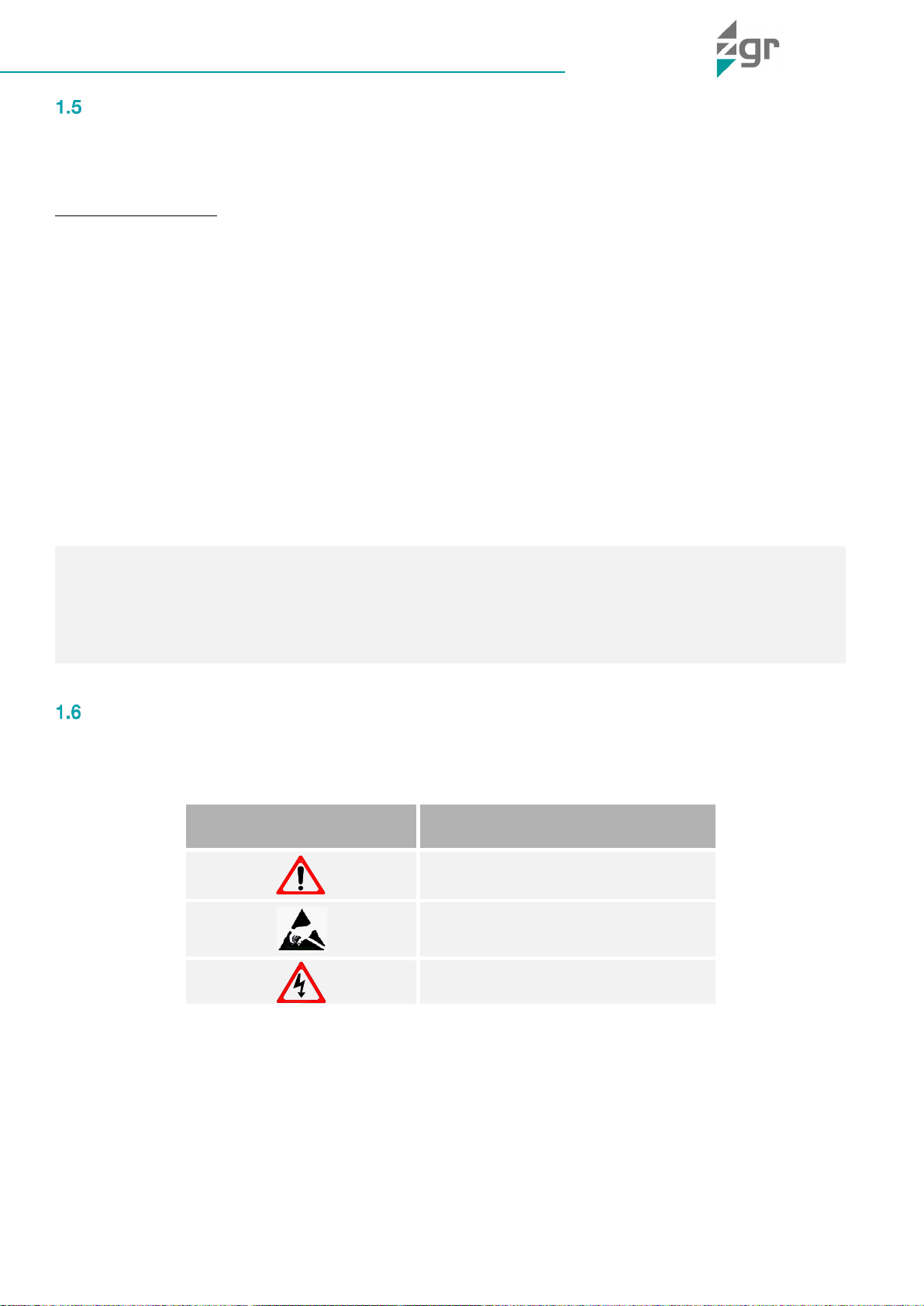
Symbol Description......................................................................................................................................6
2GENERAL DESCRIPTION.....................................................................................................................................7
Introduction..................................................................................................................................................7
Main characteristics.....................................................................................................................................7
Construction of ZGR INFLUENCE 10 - 40 KVA...........................................................................................8
3OPERATION OF ZGR INFLUENCE 10 - 40 KVA..................................................................................................9
Operation Modes .........................................................................................................................................9
3.1.1 Normal mode............................................................................................................................................9
3.1.2 Battery mode (Stored Energy Mode) .......................................................................................................9
3.1.3 Bypass mode .........................................................................................................................................10
3.1.4 ECO Mode..............................................................................................................................................10
3.1.5 Maintenance mode (Manual Bypass).....................................................................................................10
Turn on/off UPS .........................................................................................................................................11
3.2.1 Initial power-up procedure.....................................................................................................................11
3.2.2 Test procedure.......................................................................................................................................12
3.2.3 Maintenance bypass..............................................................................................................................12
3.2.4 Cold Start procedure..............................................................................................................................13
3.2.5 Shut down procedure ............................................................................................................................14
4Control panel and monitorization .......................................................................................................................15
LCD screen.................................................................................................................................................15
4.1.1 System status menu...............................................................................................................................16
4.1.2 Run.info menu........................................................................................................................................17
4.1.3 Alarm menu............................................................................................................................................18
4.1.4 Setting menu..........................................................................................................................................20
4.1.5 Maint menu ............................................................................................................................................20
4.1.6 Functions menu......................................................................................................................................21
Events and status list.................................................................................................................................22
4.2.1 Operational Status and Mode(s) ............................................................................................................22
4.2.2 Fault Information ....................................................................................................................................22
5INSTALLATION...................................................................................................................................................24
Unpack checking .......................................................................................................................................24
Mechanical installation...............................................................................................................................24
Electrical installation ..................................................................................................................................25
5.3.1 External Protective Devices ...................................................................................................................25
Connection of Power Cables.....................................................................................................................25
5.4.1 Recommended cross-sectional areas for power cables.......................................................................26
Power cable connection.............................................................................................................................26

ZGR INFLUENCE 10 - 40 KVA
Operation manual
www.zigor.com
2
5.5.1 Common input connection.....................................................................................................................27
Battery connection.....................................................................................................................................28
UPS parallel Installation .............................................................................................................................29
5.7.1 Cabinet installation.................................................................................................................................30
5.7.2 Parallel cable installation........................................................................................................................30
5.7.3 Parallel setting........................................................................................................................................30
Communications ........................................................................................................................................32
5.8.1 USB communication port definition.......................................................................................................32
5.8.2 RS232 communication port ...................................................................................................................33
5.8.3 RS485 communication port definition....................................................................................................34
5.8.4 BAT_T communication port definition....................................................................................................35
5.8.5 Dry contact port communication port definition....................................................................................35
5.8.6 REPO instruction....................................................................................................................................36
UPS remote access....................................................................................................................................36
6OPTIONS.............................................................................................................................................................38
SNMP card.................................................................................................................................................38
Relay card ..................................................................................................................................................38
7TROUBLESHOOTING.........................................................................................................................................39
Malfunctions of ZGR INFLUENCE 10 - 40 KVA.........................................................................................39
Recommended spare parts........................................................................................................................40
8MAINTENANCE...................................................................................................................................................41
Battery maintenance ..................................................................................................................................43
9TECHNICAL SPECIFICATIONS ..........................................................................................................................45
10 STANDARDS..................................................................................................................................................47
11 WARRANTY....................................................................................................................................................48
© 2022, ZIGOR
All rights reserved. The total or partial reproduction of this User Manual, or its transmission of any type or by any means, be
this mechanical or electronic, by means of photocopies, registration or other information storage or recovery procedure,
without the permission of the editor, is totally forbidden.
The contents of this manual are exact at the time it was printed. However, with the intention of complying with our aim of
continuous development and improvement, the manufacturer reserves the right to change the specifications of the product,
its operation or the contents of the Operating Manual without prior warning.

ZGR INFLUENCE 10 - 40 KVA
Operation manual
www.zigor.com
3
1PRECAUTIONS
General precautions
For your own safety and that of the unit, you must read and understand the instructions contained in this
document before starting work.
Keep these instructions in a place accessible to all the personnel who work with the unit so that they can be
consulted.
Only expert and duly authorised personnel may operate our units.
Danger warnings. When handling or accessing the interior of the ZGR INFLUENCE 10 - 40 KVA,
please remember that some parts may be live. Pay special attention to soldering points, printed
circuits, connecting terminals, relay contacts, etc. Before opening the equipment, disconnect the
voltage of all poles (both alternating and direct) and wait at least 5 minutes for the internal condensers
to discharge.
Arbitrary modifications are forbidden. The unit must not be subjected to any modification regarding its
construction or safety without express consent. Any modification will free ZIGOR of any responsibility
for any damage caused as a result of the modification. In particular, all repair work, soldering of printed circuit
boards and replacing of components, modules and printed circuit boards, without the express authorisation of
ZIGOR, is forbidden. Should spare parts be used, only ZIGOR original parts shall be utilised.
Use the unit for the purpose for which it was designed. The system supplied must be used only for the
purpose for which it was designed. Any other use is strictly forbidden. ZIGOR cannot accept responsibility for any
damage that might result from its use for any other purpose. In such cases, the user shall assume exclusive
responsibility for any risk. The use for which the unit was designed is defined in the documentation. The system
shall be exposed only to admissible environmental conditions. These are defined in the technical details provided
for the equipment.
ZIGOR accepts no responsibility for any inadequate, negligent or incorrect installation of the equipment.
•The System must be checked once the installation has been completed by a qualified technician and
before being put into operation. Should these indications not be adhered to, the warranty shall be
considered null and void.
•These units do not contain parts usable for other purposes by the user.
•Do not power up the device before a technician has checked it.
•Given the risk of electric shock or burns, do not try to open the device.
•Work inside the cabinet should be undertaken only by qualified personnel who are familiar with the safety
measures to be applied and the specific technical characteristics of the unit.
•The unit does not contain any user repairable or replaceable elements. In the case of any malfunction or
problems operating the unit, please contact ZIGOR.
•Do not place the system near power magnets as this might cause a malfunction.
•Do not block or cover the ventilation grills in the housing.
•The ZGR INFLUENCE 10 - 40 KVA is designed in accordance with current Spanish legislation. Check
these regulations against those corresponding to the country in which the unit is to be installed and
against the most restrictive regulations of the electricity supplier.
•All user controls are accessible from the exterior.
•Should you have any problems with the contents of this manual, you must ask ZIGOR for assistance.
WARNING
This supply equipment contains a lethal voltage. Comply with the instructions set out in this manual to avoid any
risk of electrical shock.

ZGR INFLUENCE 10 - 40 KVA
Operation manual
www.zigor.com
4
•This system has been designed for industrial use and not for domestic-commercial use.
•Even though all the safety systems are in place, before touching any working parts, you must check that
they are not live.
•If any liquid is spilt accidentally on the System, disconnect it and call to ZIGOR support.
•During assembly work, start-up or maintenance, wear goggles to avoid any damage to your eyes due to
accidental electric arcing.
•Use only insulated tools.
•The unit must be protected against rain and excess humidity and installed in a clean atmosphere, without
inflammable liquids, gases or oxidising substances.
•The battery may pose a risk of electric shock or burns due to its high short circuit current.
•If the batteries lose electrolyte or are physically damaged, they must be placed in a container in resistant
to corrosive liquids (acids or alkaline according to the type of battery) and prepared in accordance with
local regulations.
•If the electrolyte comes into contact with the skin, the affected area must be washed immediately with
clean water.
•For the sake of human being safety, please well earth the UPS before starting it.
•Do not throw batteries into a fire as they may explode.
•UPS models with internal batteries can be powered even when the UPS input is not connected to the
mains.
•Do not disconnect the input from the UPS and make sure the UPS is completely off before moving it or
reconfiguring the connection; otherwise, there is a risk of electric shock.
•Only authorized personnel should repair or install the batteries.
Storage precautions
The store where the material is kept must protect the material from the elements, risk of flooding or contact with
water.
The material shall be protected from any risk of overheating due to exposure to direct sunlight or through
windows.
The recommended storage temperature is from 0ºC to 40ºC. An increase of 10ºC can reduce the service life of the
battery by 50%. The recommended relative humidity is from 5% to 95%.
When the UPS or batteries are stored, it is recommended to connect them to the network for at least 12 hours
every 3 months to prevent the battery from draining excessively.
To avoid any risk of mechanical shock, do not stack the packages. These must be placed in accordance with the
silkscreen printed details on the boxes used for packaging.
WARNING
Any failure to respect these precautions may render the product warranty null and void.

ZGR INFLUENCE 10 - 40 KVA
Operation manual
www.zigor.com
5
Environmental precautions
Precautions on the transportation of the unit
Please transport the UPS system only in the original package to protect against shock and impact. The procedure
to transport of the UPS to the final location should follow the procedure:
1. Use a pallet truck to transport the UPS to the installation position.
2. Check the UPS packing.
3. packaging.
4. Check the appearance to see if the UPS is damaged or not during the transportation, do not switch on the
UPS if any damage found. Please contact the dealer right away.
5. Check the accessories according to the packing list and contact the dealer in case of missing parts.
Dispose of the packaging in an ecological way: ZIGOR, based on the exceptions detailed
in the First Additional Provision of Law 11/1997 on commercial or industrial packaging,
informs that the final holder of the waste of used containers and packaging, as responsible
for them, you must deliver them in appropriate conditions for reuse, to an authorized
recuperator, recycler or re-valuer.
The subsets of the system are recyclable products and cannot be treated as household / municipal waste at
the end of its useful life.
To preserve the environment, manage them in accordance with current environmental regulations and
requirements in each country or community. In case of doubt, consult the manufacturer.
Correct product disposal: This electrical-electronic device (AEE) is marked with the
symbol of compliance with the European Directive 2012/19 / EU (WEEE) regarding used
electrical and electronic equipment (Waste electrical and electronic equipment WEEE, RD
110/2015).
The Directive provides the general framework valid throughout the European Union for the
removal and reuse of waste from EEE.
To dispose of this product and ensure its proper management, follow the current local
environmental legislation and regulations. In this way it will contribute to conserve the
environment.
Correct disposal of batteries: Used batteries are reusable consumer products and a recycling
process must be carried out.
Used batteries that do not go through the recycling process must be disposed of according to
the instructions regarding special waste, in accordance with the regulations and environmental
requirements in force in each country or community. This requirement applies in the European
Union and in those places where separate collection systems are available.
In case of doubt, consult the manufacturer.
In this way it will contribute to conserve the environment.

ZGR INFLUENCE 10 - 40 KVA
Operation manual
www.zigor.com
6
Precautions on receiving the unit
Visually check that the warehouse location is adequate by checking its characteristics (clean, free of leaks with
good ventilation); the floor must be level and have sufficient load resistance for the equipment.
Checking the material
Do not lean the UPS when moving it out from the packaging.
On receiving the material, a visual inspection should be made in order to detect any anomalies that may have
occurred during transport.
List and check all the items indicated on the delivery note. Should any component be missing, notify the
forwarding agent within the established deadline.
Extract all parts from the packaging and examine the unit for any damage caused during transport.
Report any damage to the forwarding agent and ZlGOR.
Check that the material delivered corresponds to the delivery note. Check the manufacturer's label placed at the
rear or on one side of the unit.
Responsibility for the loss or damage of products shall transfer to the Customer from the moment ZIGOR, places
these at his disposal in the place indicated by the Customer.
Symbol Description
The safety symbols cited in this manual are shown in Table 1-1, which are used to inform readers of safety issues
that should be obeyed when installation, operation and maintenance.
SECURITY SYMBOL
INDICATION
Attention
Sensitive to electrostatic discharge
Risk of electric shock
Table 1-1 Symbols meaning
From then on, the customer will have 24 hours to make any claim under guarantee for any anomaly in the
amount or quality of the products received, providing details of the material received in bad condition after
reporting this circumstance on the forwarding agent's delivery note on reception.
Should the customer not report any defect within 24 hours, it will be understood that he has accepted delivery
of the unit.

ZGR INFLUENCE 10 - 40 KVA
Operation manual
www.zigor.com
7
2GENERAL DESCRIPTION
Introduction
ZGR INFLUENCE 10 - 40 KVA consists on a small-sized UPS, in tower format and available in 10K, 15K, 20K,
30K and 40K models with three-phase input and output.
ZGR INFLUENCE 10 - 40 KVA incorporates the most advanced DSP (Digital Signal Processor) technologies, 3-
be configured and monitored UPS status in an
intuitive way and direct without the need for external software.
Moreover, it is parallelable up to 4 units with common battery setup, being one of the market smaller footprint
solutions.
ZGR INFLUENCE 10 - 40 KVA can solve most of the power supply problems, such as blackout, over-voltage,
under-voltage, voltage sudden drop, oscillating of decreasing extent, high voltage pulse, voltage fluctuation,
surge, inrush current, harmonic distortion (THD), noise interference, frequency fluctuation, etc..
This UPS can be applied to different applications from computer device, automatic equipment, communication
system to industry equipment. They are available in a Dual Input version that allows a three-phase auxiliary
bypass grid.
Main characteristics
•3 Phase In / 3 Phase Out
•Online double conversion with DSP control
•Dual input (optional)
•Power factor of 0,9
•Low input and output current distortion
•Efficiency of 94,5 %
•Parallelable up to 4 units
•Active ECO function: Minimize UPS self-consumption and improves efficiency up to 98%
•Allows common battery in parallel mode
•
•Compatible with generator sets
•Integrated Input/output/bypass MCB protections
•Standard models are designed for external long autonomy battery
•Configurable battery charge voltage and current
•Periodic battery test configurable
•Cold start and Auto Restart function
•Compatible with Ni-Cd / LiIon (on demand)
•Internal batteries (optional)
•Communications: 2 independent bays for smart cards and dry contacts

ZGR INFLUENCE 10 - 40 KVA
Operation manual
www.zigor.com
8
Construction of ZGR INFLUENCE 10 - 40 KVA
Outlook views of ZGR INFLUENCE 10 - 40 KVA (Fig. 2-1 y Fig. 2-2):
Fig. 2-1 Front view
ZGR INFLUENCE 10 - 40 KVA
Fig. 2-2 Side view
ZGR INFLUENCE 10 - 40 KVA
(1) LCD display
(2) RS485 port (service port)
(3) Drycontact port
(4) Parallel port 1
(5) USB comm. port
(6) Parallel port 2
(7) RS232 comm. port
(Only used on internal battery models)
(9) Remote EPO port
(10) Mains breaker
(11) Terminal block
(12) Cold Start button
(13) History logger port
(14) Intelligent slot 1
(15) Maint. Bypass breaker
(16) Intelligent slot 2
(17) Output breaker
(18) Earth terminals
Fig. 2-3 Rear view
ZGR INFLUENCE 10 20 KVA
(terminal block without cover)
Fig. 2-4 Rear view of
ZGR INFLUENCE 30 40 KVA
(terminal block without cover)
Connections avalilable on rear panel for ZGR INFLUENCE 10 20 KVA (Fig. 2-3), and ZGR INFLUENCE 30 40
KVA (Fig. 2-4).

ZGR INFLUENCE 10 - 40 KVA
Operation manual
www.zigor.com
9
3OPERATION OF ZGR INFLUENCE 10 - 40 KVA
Operation Modes
This UPS adopts advanced three-stage charging method:
1st stage: high current constant current charging to guarantee to charge back to 90%;
2nd-stage: Constant Voltage in order to vitalize battery and make sure batteries are fully charged
3rd stage: floating mode.
With this 3-stage charging method, it extends the life of the batteries and guarantees fast charging.
Besides, the ZGR INFLUENCE 10 - 40 KVA is a double-conversion on-line UPS that may operate in the following
alternative operation modes.
3.1.1 Normal mode
The rectifier/charger derives power from the AC Mains and supplies DC power to the inverter while floating and
boosting charge the battery simultaneously. Then, the inverter converts the DC power to AC and supplies to the
load (Fig. 3-1).
Fig. 3-1 Normal mode
3.1.2 Battery mode (Stored Energy Mode)
If the AC mains input power fails, the inverter, which obtains power from the battery, supplies the critical AC load.
There is no power interruption to the critical load. The UPS will automatically return to Normal Mode when AC
recovers (Fig. 3-2).
Fig. 3-2 Battery mode

ZGR INFLUENCE 10 - 40 KVA
Operation manual
www.zigor.com
10
3.1.3 Bypass mode
If the inverter is out of order, or if overload occurs, the static transfer switch will be activated to transfer the load
from the inverter supply to bypass supply without interruption to the critical load (Fig. 3-3).
In the event that the inverter output is not synchronized with the bypass AC source, the static switch will perform
a transfer of the load from the inverter to the bypass with power interruption to the critical AC load. This is to avoid
paralleling of unsynchronized AC sources. This interruption is programmable but typically set to be less than an
electrical cycle e.g. less than 15 ms (50 Hz) or less than 13,33 ms (60 Hz).
Fig. 3-3 Bypass mode
3.1.4 ECO Mode
When the UPS is at AC Mode and the requirement to the load is not critical, the UPS can be set at ECO mode in
order to increase the efficiency of the power supplied (Fig. 3-4). At ECO mode, the UPS works at Line-interactive
mode, so the UPS will transfer to bypass supply. When the AC is out of set window, the UPS will transfer from
bypass to Inverter and supplies power from the battery, and then the LCD shows all related information on the
screen.
Fig. 3-4 ECO mode
3.1.5 Maintenance mode (Manual Bypass)
A manual bypass switch is available to ensure continuity of supply to the critical load when the UPS is out of order
or in repair and this manual bypass switch bears for equivalent rated load (Fig. 3-5).

ZGR INFLUENCE 10 - 40 KVA
Operation manual
www.zigor.com
11
Fig. 3-5 Maintenance mode
Turn on/off UPS
3.2.1 Initial power-up procedure
1. Set the Power Switch (Fig. 3-6).
Fig. 3-6 Power switch of the UPS
** This switch is dedicated to cut off internal battery current drain during storage or transpor. It is used only by
internal battery UPS models. If external battery cabinet is used, this switch must be always ON.
WARNING
Make sure grounding is properly done.
WARNING
Check to see if the load is safely connected with the output of the UPS. If the load is not ready to receive power
from the UPS, make sure that it is safely isolated from the UPS output terminals.

ZGR INFLUENCE 10 - 40 KVA
Operation manual
www.zigor.com
12
2. Switch ON battery breaker.
3. Switch ON Mains input switch (I/P Switch) (Fig. 3-7).
If the Rectifier input is within voltage range, the rectifier will start up in 30 seconds then the inverter will start up.
During Rectifier start up, the UPS will remains in Static Bypass mode. (bypass LED will light up)
When complete, it continues on Battery Charging mode and Inverter start-up.
Fig. 3-7 UPS input switch
If all procedure is OK, UPS will finally transfer from Bypass mode (yellow LED off) to Inverter mode. (ONLINE
green LED)
No matter whether the UPS can work normally or any issue is detected, all the status will be shown on the LCD
display.
4. Verify all your loads are ready and turn ON output breaker.
3.2.2 Test procedure
UPS in fully stable ONLINE working mode and fully charged batteries:
1. Switch off the mains power to UPS to simulate utility failure, the rectifier will turn off and the battery
should feed energy through the inverter without interruption. At this time, the on battery mode yellow LED
should be turned on and battery will be on discharging mode..
2. Switch on the MAINS to simulate utility recovery, the rectifier will restart automatically after 20 seconds
and the inverter will supply to the load. It is suggested to use Dummy loads for testing. The UPS can be
loaded up to its maximum capacity during load test.
3.2.3 Maintenance bypass
To supply the load via Mains, you may simply active the internal mechanical bypass switch.
When maintenance bypass cover is removed, UPS will transfer to bypass mode automatically.
WARNING
If the UPS is operating normally, It may take about 60 seconds to perform full self-test completely.
WARNING
The loads are not protected by the UPS when the internal mechanical bypass system is active.
Any mains fluctuation, interference, energy loss,... will be applied directly to loads.

ZGR INFLUENCE 10 - 40 KVA
Operation manual
www.zigor.com
13
3.2.3.1 Switch to mechanical maintenance bypass
1. Open the cover of maintenance switch, the UPS turns to bypass mode automatically.
2. Turn ON Maintenance breaker.
3. Turn OFF Battery breaker if full UPS isolation is nedded.
4. Turn OFF Mains breaker.
5. Turn OFF Output breaker.
At this time the bypass source will supply to the load through the MAINTENANCE breaker.
3.2.3.2 Switch to normal operation (from mechanical bypass)
1. Turn ON Battery, and following turn ON Output breaker.
2. Turn ON Mains breaker and wait until fully start-up process.
3. Switch OFF the maintenance bypass breaker and put maintenance switch cover.
At this time the bypass source will supply to the load through the MAINTENANCE breaker.
3.2.4 Cold Start procedure
1. Turn ON Power Switch on rear panel. (power will feed from battery to internal electronics.
(Only valid for internal battery UPS. On external battery models this switch needs to be always ON)
2. Turn ON Battery breaker.
3. Turn ON Output breaker.
4. Trigger the Cold start button, position 11 of the below drawing (Fig. 3-8).
Fig. 3-8 Cold Start
When battery is under normal working ranges, rectifier starts operation, 30s later, ithen nverter starts and
operates. UPS will be working on battery discharging mode (yellow LED On).
WARNING
If the UPS is running normally, for more security, it is recommended to transfer to static bypass initialy by LCD
-5.
WARNING
Never attempt to switch the UPS back to normal operation until you have verified that there are no internal UPS
or externa faults.
WARNING
Follow these procedures when the input AC Utility Failure, but battery energy is available.

ZGR INFLUENCE 10 - 40 KVA
Operation manual
www.zigor.com
14
3.2.5 Shut down procedure
3.2.5.1 Online mode
1. Turn OFF Power Switch on rear panel. (power will feed from battery to internal electronics.
(Only valid for internal battery UPS. On external battery models this switch needs to be always ON)
1. Turn OFF Battery breaker. (UPS could notify battery fault alarm)
2. Turn OFF Mains breaker. (UPS could notify alarma during internal electronics discharge)
3. Turn OFF Output breaker. (Loads will be powered off)
4. Normally the primary input distribution panel is often located far away from the UPS area, so a label
should be posted to advise service personnel that the UPS circuit is under maintenance.
3.2.5.2 Battery mode
1. Turn OFF Power Switch on rear panel. (power will feed from battery to internal electronics.
(Only valid for internal battery UPS. On external battery models this switch needs to be always ON)
2. Turn OFF Battery breaker. (UPS could notify battery fault alarm)
3. Turn OFF Output breaker. (Loads will be powered off)
4. If other breakers are not previously turned OFF, now you can do it.
5. Normally the primary input distribution panel is often located far away from the UPS area, so a label
should be posted to advise service personnel that the UPS circuit is under maintenance.
WARNING
This procedure should be followed to completely shut down the UPS and the output loads.
After all power switches, isolators and circuit breakers are opened, there will be no output.
WARNING
Wait for about 5 minutes for the internal DC bus bar capacitors to be completely discharged to avoid any
electric shock risk.

ZGR INFLUENCE 10 - 40 KVA
Operation manual
www.zigor.com
15
4Control panel and monitorization
LCD screen
1. status LED
* UPS fail
* Bypass mode
* Battery mode
* Inverter ON
2. LCD touch screen
Fig. 4-1 LCD Control panel
The elements of the control panel are (Fig. 4-1):
1. LED ( )
2. LCD display
In the LCD screen the following elements and areas are shown (Fig. 4-2):
Fig. 4-2 Distribution of the control panel window
From any window, click the main block to enter the main data display window, click return to return to the
previous window, click home page to return to the main page.
WARNING
The display could show different texts and translation depend on selected language, and could show more
functions than those described in this manual.
Contact ZIGOR service support for help.

ZGR INFLUENCE 10 - 40 KVA
Operation manual
www.zigor.com
16
4.1.1 System status menu
This menu displays the UPS operating flow chart, and there are the data entrance of input, output,
battery (Fig. 4-3).
Fig. 4-3 Sys. status menu
4.1.1.1 Bypass submenu
Click the bypass block to enter the bypass data display window (Fig. 4-4).
Fig. 4-4 Bypass submenu
4.1.1.2 Mains submenu
Click on the mains icon to enter the mains data window (Fig. 4-5).
Fig. 4-5 Mains submenu

ZGR INFLUENCE 10 - 40 KVA
Operation manual
www.zigor.com
17
4.1.1.3 Output submenu
Click the output block to enter the output data display window (Fig. 4-6).
Fig. 4-6 Output submenu
4.1.1.4 Battery submenu
Click the battery block to enter the battery data display window (Fig. 4-7).
Fig. 4-7 Battery submenu
4.1.2 Run.info menu
Click on «Run.info» icon to enter to detail working information page (Fig. 4-8).
Fig. 4-8 Runn. Info menu

ZGR INFLUENCE 10 - 40 KVA
Operation manual
www.zigor.com
18
Click on the Run time icon to enter the status data window, can see the breaker status (Fig. 4-9).
Fig. 4-9 Status data window
Click on the ENV data icon to enter the status data window, the user can see the temperature data after
connected to temperature sensor (Fig. 4-10).
Fig. 4-10 Temperature data window
4.1.3 Alarm menu
It allows viewing the alarms and history of the UPS, and activating or deactivating the buzzer (Fig. 4-11).
Fig. 4-11 Alarm menu
This manual suits for next models
5
Table of contents
Other ZGR UPS manuals