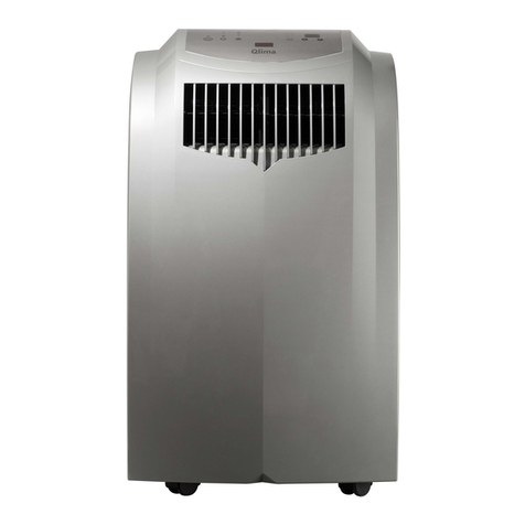
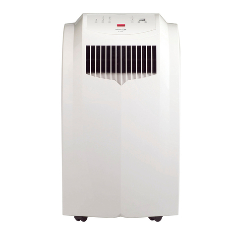
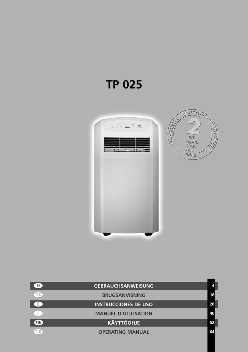
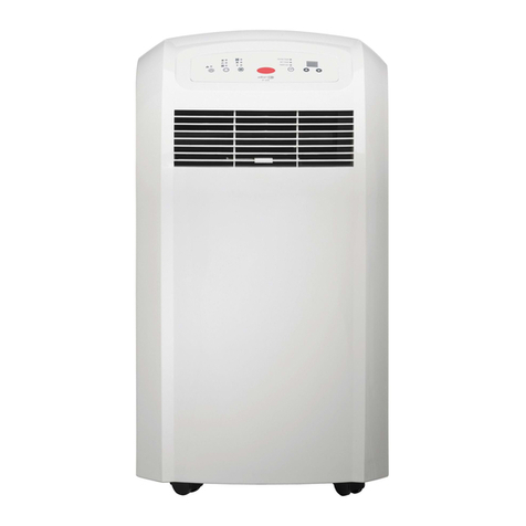
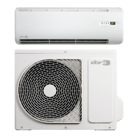
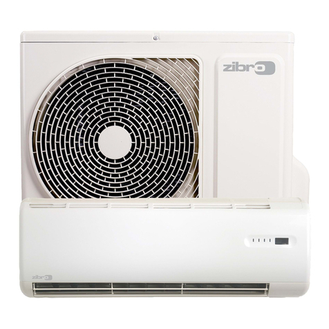
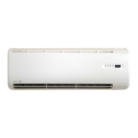
Zibro PX 643 User manual

4
20
36
52
68
84
100
116
BEDIENUNGSANLEITUNG
BRUGSANVISNING
INSTRUCCIONES DE USO
MANUEL D'UTILISATION
OPERATING MANUAL
ISTRUZIONI D’USO
GEBRUIKSAANWIJZING
INSTRUKCJA OBSŁUGI
2
6
5
3
4
>
1
:
PX 643

1. READ THE DIRECTIONS FOR USE FIRST.
2. IN CASE OF ANY DOUBT, CONTACT YOUR DEALER.
4
68
IMPORTANT
COMPONENTS
Control Panel
Air outlet
Carrying handle
Caster wheels
Water container
Air filter
Air inlet
Exhaust air outlet
Cord storage
Water stopper /
drainage point
Connection tube
Cabinet cover for
quick connector
shielding
Bracket
Spanners
Remote control
Screws
Protection caps for
connector
A
B
C
4
E
F
G
H
I
J
K
L
M
N
O
P
Q
M
5
O
P
Q
7
6
9
L
J
4
B
1
3
K
N
8
(8x)
(2x)

4
69
Dear Sir, Madam,
Congratulations on the purchase of your air conditioner. In addition to air cooling, this air
conditioner has three other functions: air dehumidification, air circulation and air filtration.
The mobile air conditioner is easy to operate and move. You have acquired a high quality
product that will provide you with many years of pleasure, on condition that you use it
responsibly. Reading these instructions for use before operating your air conditioner will
optimise its life span.
We wish you coolness and comfort with your air conditioner.
Yours sincerely,
PVG International B.V.
Customer service department

ASAFETY INSTRUCTIONS
Install the device only when it complies with local regulations, by-laws and
standards. The unit is only suitable for use in dry locations, indoors. Check the
mains voltage and frequency. This unit is only suitable for earthed sockets,
connection voltage 220-240 V. / 50 Hz.
Before connecting the unit, check the following:
• The voltage supply must correspond with the mains voltage stated on the
rating label.
• The socket and power supply must be suitable for the current stated on the
rating label.
• The plug on the cable of the device must fit into the wall socket.
• The device must be placed on a flat and stable surface.
The electricity supply to the device must be checked by a recognised professional
if you have any doubts regarding the compatibility.
•This device is manufactured according to CE safety standards. Nevertheless,
you must take care, as with any other electrical device.
• Do not cover the air inlet and outlet grill.
• Empty the water reservoir before moving the unit.
• Never allow the device to come into contact with chemicals.
• Never spray the unit with or submerge in water
• Do not insert objects into the openings of the unit.
• Always remove the plug from the electric power supply before cleaning or
replacing the unit or components of the unit.
• Never use an extension cable to connect the device to the electric power
supply. If there is no suitable, earthed wall socket available, have one
installed by a recognised electrician.
• For safety reasons take care when children are in the surrounding of the
device, as with any other electrical device.
• Have any repairs only carried out by a recognised service engineer or your
supplier. Follow the instructions for use and maintenance as indicated in the
user manual of this device.
• Always remove the plug of the unit from the wall socket when it is not in use.
•A damaged power cord or plug must always be replaced by a recognised
electrician or your supplier.
GIMPORTANT
The device MUST always have an earthed connection. If the power
supply is not earthed, you may not connect the unit. The plug must
always be easily accessible when the unit is connected. Read these
instructions carefully and follow the instructions.
4
70

4
71
BINSTALLATION
The indoor and outdoor units are portable and can easily be moved from one
room to another. They are connected to each other by a 2.5 meter flexible tube.
Ensure that the units are positioned upright and on a level surface.
When handling the units, take the following into account:
INSTALLATION OF THE INDOOR UNIT
Place the loose filters in the filter holder of the indoor unit.
• Take the filter holder out of the air conditioner
• Open the filter holder and place the active carbon filter (black) and 3M™
Filtrete™ filter (white) in the filter holder.
• Place the filter fixing component back in the holder.
• Place the filter holder back in the air conditioner.
Please keep a distance of at least 50 cm between the indoor unit and the wall
or other objects to ensure proper air circulation.
Do not operate the unit inside the bathroom, shower, or in any other very
humid environment.
GWARNING
The air must flow freely through the indoor unit. Any blockage can lead
to damage or improper operation of the air conditioner.
3
2
1
GWARNING
Before using the air conditioner it should be left in an upright position
for at least 2 hours.
GWARNING
• Don’t lift, or move by pushing, the air conditioner at the back side,
but always at the front side (see pictures).
GATTENTION!
• Never use the device with a damaged power cord, plug, cabinet or
control panel. Never trap the power cord or allow it to come into
contact with sharp edges.
• Failing to follow the instructions may lead to nullification of the
guarantee on this device.
50 cm
50 cm

INSTALLATION OF THE OUTDOOR UNIT
The outdoor unit can be placed on the floor (of a balcony) or hung on a wall. The
location for the outdoor unit has to be well ventilated (to exhaust heat) and
reachable from the indoor; such as under a window, on a veranda or in a corridor.
The outdoor unit does not necessarily have to be mounted to the bracket. The
maximum distance from the top of the outdoor unit to the floor is 150 cm.
Please keep a distance of at least 5 cm between the outdoor unit air inlet and wall
or other objects and a distance of at least 120 cm between the outdoor unit
exhaust air outlet and wall or other objects to ensure proper air circulation. If
possible, put the outdoor unit in the shade.
Condensated water will be evaporated by the outdoor unit. Excessive humidity
can create a water flow through the outdoor unit. Take care of proper water
drainage to avoid leaking of water to inconvenient places. Ensure that the
outdoor unit is positioned upright and on a level surface.
A. Placing the outdoor unit just outside.
The outdoor unit can be set on the floor or on any other surface. Ensure that
water can be drained from the outdoor unit.
B. Hanging the outdoor unit on a wall.
Drill eight holes in the wall where the outdoor unit has to be mounted
(Note: The maximum distance from the top of the outdoor unit to the floor
is 150 cm).
Firmly screw the mounting bracket Mto the wall.
Make sure that the two spacers are mounted on the lower part of the
outdoor unit keeping the unit vertically parallel to the wall.
Hang the outdoor unit.
To avoid damaging the connection tube, leave the window ajar.
Close the window or door as much as possible to prevent outside air from
entering the room.
GWARNING
• The air must flow freely through the outdoor unit. Any blockage can
lead to damage or improper operation of the air conditioner.
• Take care to prevent any bow or bend in the connection tube.
•The condensation water must flow freely. Blockage of the drainage
tube can result in water leakage or improper operation of the unit.
Avoid leakage/flowing from water to inconvenient places.
•Be aware for danger caused by falling of the outdoor unit.
6
5
4
3
2
1
4
72
120 cm (min.)
5 cm (min.)
120 cm (min.)
5 cm (min.)
150 cm
(max.)

4
73
COPERATION
1. CONNECTING TO THE MAIN
Insert the plug in the wall socket. Then press to switch the unit on or off. A
buzzer will beep, and the LCD will display 12:00 o’clock as default.
2. SETTING THE CLOCK
Press the push button for 3 seconds to set the clock. The 2 left digits of the
4 digits on the LCD-display will flash.
Press or to adjust the hour.
Press momentarily, the 2 right digits of the 4 digits will flash.
Press or to adjust the minutes of the clock.
Press the push button for 3 seconds again to activate the clock.
3. TEMPERATURE SETTING UP/DOWN
If you want to change the set temperature press or to set the temperature.
The 2 digit display will indicate the set temperature.
4. MODE SWITCH
Push the button successively until the icon representing the desired mode is
appearing (=> Cool => Fan => Cool => etc).
On the LCD-display you will see: Cooling
Fan only
Each time the unit starts, it starts operating in coolmode with a set temperature
of 22°C. The fan speed will be selected automatically.
5. FAN SPEED SETTING
If you prefer a constant fan speed instead of the auto fan speed, push the
push button successively; the fan icon on the LCD-display will rotate
accordingly.
• Fast - for the turbo speed
• Normal - for the medium speed
•Slow - for the slow speed
• Alternating - for the auto fan speed (In the cooling mode only!)
GNOTE
Reaching the set temperature is up to surrounding room conditions.
5
4
3
2
1
88::8888
8888::88

6. TIMER SETTING
The timer can be set in the following configurations:
ON
Programming the timer for ON - when the unit is OFF.
Press the push button; the 2 left digits of the 4 digits on the LCD display
are flashing.
Press or to adjust the hour.
Press the push button again, the 2 right digits of the 4 digits are flashing.
Press or to adjust the minutes of the clock in intervals of 5 minutes.
The timer is set. After 10 seconds the time display returns.
The circular time scale will be on between the ON programmed times until 24:00.
The flashing bar on the time scale indicates the real time and moving a phase
every 30 minutes ahead until it reaches the ON timer time, then the black
segments in the circular time scale will disappear.
OFF
Programming the timer for OFF - when the unit is running.
Press the push button; the 2 left digits of the 4 digits on the LCD display
are flashing.
Press or to adjust the hour.
Press the push button again, the 2 right digits of the 4 digits are flashing.
Press or to adjust the minutes of the clock in intervals of 5 minutes.
The timer is set. After 10 seconds the time display returns.
The circular time scale will be on between the present time to the OFF
programmed time. The flashing bar on the time scale indicates the real time and
moving a phase every 30 minutes ahead until it reaches the OFF timer time, then
the black segments in the circular time scale will disappear.
4
3
2
1
4
3
2
1
4
74
88::8888
8888::88
88::8888
8888::88

4
75
Repeat OFF & ON
Programming the timer for repeat OFF & ON - when the unit is running.
Press the push button; the 2 left digits of the 4 digits on the LCD display
are flashing.
Press or to adjust the hour.
Press the push button again, the 2 right digits of the 4 digits are flashing.
Press or to adjust the minutes of the clock in intervals of 5 minutes.
The timer is set. After 10 seconds the time display returns.
Repeat the above procedure while the digits are still flashing for setting the
ON.
The circular time scale will be on between the 00:00 time to the timer time off,
and from the time on till 24:00. The flashing bar on the time scale indicates the
real time and moving a phase every 30 minutes ahead. The unit will operate
according to the timer setting daily.
Repeat ON & OFF
Programming the timer for repeat ON & OFF - when the unit is not running.
Press the push button; the 2 left digits of the 4 digits on the LCD display
are flashing.
Press or to adjust the hour.
Press the push button again, the 2 right digits of the 4 digits are flashing.
Press or to adjust the minutes of the clock in intervals of 5 minutes.
The timer is set. After 10 seconds the time display returns.
Repeat the above procedure while the digits are still flashing for setting the
OFF.
The circular time scale will be OFF between the 00:00 time to the timer time ON,
and from the time OFF until 24:00. The flashing bar on the time scale indicates the
real time and moving a phase every 30 minutes ahead. The unit will operate
according to the timer setting daily.
After a power failure (e.g. after plug out of the wall socket) you have to program
the timer setting again.
5
4
3
2
1
5
4
3
2
1
88::8888
8888::88
on
off
88::8888
8888::88

7. CANCELLING THE TIMER FUNCTION
In order to cancel the timer programming press the push button momentarily,
then it will return to the time display. The daily mode will be cancelled as well.
The black segments in the circular time scale will disappear.
8. AIRFLOW
Direct the airflow by adjusting the grill on top of the air conditioner. Move the
grill, by pushing or pulling, in the middle (see illustration). This to avoid a false
position of the grill. Adjusting the airflow is as well possible by moving the
direction of the vertical louvers.
9. SLEEP MODE FUNCTION
The sleep mode function adjusts the set temperature of the unit to the thermal
needs of the body falling asleep as follow:
• In the COOL or AUTO COOL mode
The set temperature will increase 1ºC after 1 hour and a further 1ºC after 2
hours.
• No FAN mode under SLEEP mode operation
• Default fan speed: LOW
Press the push button to operate the sleep mode.
Press the push button again in order to cancel the sleep mode.
10. DEHUMIDIFICATION
Under normal circumstances the condensation water is pumped to the outdoor
unit through the connection tube. When the waterflow is blocked or the position
of the outdoor unit is to high, water may accumulate in the indoor water
container of the unit.
See chapter E for instructions regarding drainage of the internal water container.
DAIR FILTER
This air conditioner is equipped with a 3 layer filter to clean the circulated room
air.
a. Screen filter; to remove bigger dust particles.
b. 3M™ Filtrete™ filter; to remove unhealthy particles from the air such as
pollen, bacteria, animal dander and dust.
c. Active carbon filter; to remove odours.
GNOTE!
The active carbon filter and the 3M™ Filtrete™ filter are delivered in a
plastic packaging. Don’t forget to install these filters. These filters take
away unhealthy particles out of the room environment.
2
1
4
76

4
77
The filter frame on the backside of the unit can be opened. The active carbon
filter and 3M™ Filtrete™ filter can be installed or removed. The screen filter is
part of the filter frame (see illustration).
a. The screen filter has to be cleaned regularly with a vacuum cleaner to avoid
blocking of the air flow.
b. The positive/negative electrostatically charged 3M™ Filtrete™ filter is recom-
mended to be changed every 3 months. Unusual dirt, construction work, pets,
the presence of smoke and running the air-conditioning unit continuously
can shorten the life time of the 3M™ Filtrete™ filter.
New filter Recommended change of filter
c. The active carbon filter can be cleaned with a vacuum cleaner when dusty but
has to be changed at the same time as the 3M™ Filtrete™ filter.
Filter installation:
Slide out the filter frame from the unit.
Separate the filter fixer from the filter frame (see fig. 1).
Remove the active carbon filter and the 3M™ Filtrete™ filter from its plastic
bag.
Insert the active carbon filter into the filter frame (see fig. 2).
Insert the 3M™ Filtrete™ filter into the filter frame (see fig. 3).
Fix the filter by reassembling the fixer into the filter frame (see fig. 4).
GNOTE!
• Remove the 3M™ Filtrete™ filter and active carbon filter before
seasonal storage and install new filters at the beginning of the new
season. The old filters can be disposed in the ‘Non-biological garbage
container’.
• Replacement filter packages are available at your dealer.
•To run the unit without active carbon filter and/or 3M™ Filtrete™
filter does not bring any harm to the air conditioner. In that case
odours and unhealthy dust are not removed from the circulated air.
6
5
4
3
2
1
fig. 1
fig. 4
fig. 2
fig. 3

EEMPTY INTERNAL WATER CONTAINER
When the water flow to the outdoor unit is blocked, or the position of the
outdoor unit is too high, water may accumulate in the internal water container of
the unit. When the internal water container is full the backlight on the LCD-
display will be flashing. The unit will switch off automatically. To empty the water
container do the following:
Switch off the unit and remove the plug from the wall socket.
Do not move the unit. Doing this can result in water leakage, damaging your
floor or carpet.
Place the water container 5on the floor underneath the permanent
drainage point J.
Remove the water stopper Jand rubber plug from the drain and let the
water run out. The water container has to be emptied several times before all
water will be drained (ca. 1,5 liters).
Replace the rubber plug and water stopper J, put the plug into the wall
socket, and switch the unit on. The warning signal should be off.
FREMOTE CONTROL
The unit responds to all signals that are sent by the remote control O. There will
be a beep sound from the unit after receiving the signal. The operation of the
unit (see chapter C) by remote control, is almost identical to the operation by the
circular control panel.
The only exception is the clock function.
Instead of the common push button for setting the actual time and for pro-
gramming the timer, there are 3 push buttons on the remote control as follows:
• - for setting the actual time
•TIMER ON - for programming the time for the unit ON
• TIMER OFF - for programming the time for the unit OFF
GNOTE!
When the air conditioner is in use, under normal circumstances the
condensed water will be discharged through the outdoor unit 8.
5
4
3
2
1
4
78

4
79
G(DIS)CONNECTING THE INDOOR AND OUTDOOR UNIT
(FOR QUALIFIED PERSONNEL)
DISCONNECTING
Switch off the unit, remove the plug from the mains and leave it idle for at
least 30 minutes.
Open the cabinet cover for quick connector shielding L.
Disconnect the electric cable (A).
Disconnect the drain tube (C).
Remove the metal brackets which are holding the tubes and wire.
Remove the isolation material from the connectors.
Disconnect the refrigerant tubes (B and D) using the spanners Nprovided.
The terminals are fitted with automatic self-sealing valves to prevent the
refrigerant from leaking. Loosen the nuts quickly, so the seal is made
promptly. During the operation take extreme care not to break or bend the
refrigerant tubes.
Screw the protection caps for the connectors Qonto the ends of the
refrigerant tubes connectors.
CONNECTING
Pass the connection tube through the hole (at least Ø 50 mm) in the wall.
Remove the protection caps from the ends of the refrigerant tubes.
Reconnect the refrigerant tubes (B and D) according to the marking (tighten
the nuts quickly to make a good seal), the drain tube (C) and the electrical
cable (A).
Put the isolation material around the connectors / tubing again.
Put back the metal brackets which are holding the tubes and wire.
5
4
3
2
1
GIMPORTANT
• Never store the indoor/outdoor unit disconnected.
• Do not operate the indoor unit if the quick-connectors are
disconnected. This might cause harm to people and property.
8
7
6
5
4
3
2
1

Close the cabinet cover for quick connector shielding L.
Store the protection caps Qin a safe place.
HCLEANING
Clean the housing with a soft, damp cloth. Never use aggressive chemicals, petrol,
detergents or other cleansing solutions. Clean the screen filter regularly with a
vacuum cleaner. See also chapter D “Air filter”.
ISTORAGE
Empty the internal water container (refer to Chapter E).
Clean the screen filter (refer to Chapter H). Remove 3M™ Filtrete™ filter and
active carbon filter.
• Remove the 3M™ Filtrete™ filter and active carbon filter before seasonal
storage and install new filters at the beginning of the new season. The
old filters can be disposed in the ‘Non-biological garbage container’.
•Replacement filter packages are available at your dealer.
Put the unit in air circulation mode for a few hours to ensure that the inside
becomes completely dry.
Store the cable as shown. Protect the unit against dust and store in a dry
place, not accessible to children.
4
3
2
1
GNOTE!
Never use the air conditioner without the screen filter.
GWARNING!
First of all switch off the unit and pull the plug out of the wall socket.
GIMPORTANT
Always ensure that the quick-connection openings are clean. Attach the
caps to quick-connectors whenever they are opened.
GWARNING
After connecting the refrigerant tubes, take care that these are well
isolated again. If this is not done properly, damage because of
condensation water can occur!
7
6
4
80

4
81
JTROUBLE SHOOTING
Never try to repair or dismantle the air conditioner yourself. Incompetent repairs
result in loss of warranty and can endanger the user.
Problem Cause Solution
No power supply.
Connect to a functioning outlet
and switch on.
Is the LCD light flashing.
Empty the internal water
container (refer to Chapter E).
Timer function is active.
De-activate Timer function (refer
to Chapter C).
In direct sunlight. Close curtains.
Windows or doors open, many
people or heat sources in room.
Close doors and windows, or
place an extra air conditioner.
Dirty filter.
Clean or replace filter (refer to
Chapter D).
Air inlet or air outlet blocked. Remove blockage.
Room temperature lower than
selected value.
Change temperature selection.
The unit is noisy. Unit stands uneven.
Place on even surface (less
vibrations).
The compressor
does not work.
Overheat protection probably
activated.
Wait 3 minutes until the
temperature has decreased, and
turn on the unit again.
Distance too big.
Remote control signal not
detected by control panel.
Batteries empty. Replace the batteries.
The outdoor unit is placed to
high.
The maximum distance from the
top of the outdoor unit to the
floor is 150 cm (Refer to chapter
B).
The connection tube is bent to
sharp.
Do not bent the connection tube
to sharp. Let the condensation
water flow freely.
The internal
water tank runs
full to fast.
The unit does
not function.
The unit does
not seem to
perform.
Remote control
does not
function.
Make sure the remote control is
correctly aimed at the control
panel.
GNOTE!
Do not store the units disconnected, to prevent leakage of refrigerant.

KGUARANTEE CONDITIONS
The air conditioner is supplied with a 24-month guarantee, commencing on the
date of purchase. All material and manufacturing defects will be repaired or
replaced free of charge within this period. The following rules apply:
1. We expressly refuse all further damage claims, including claims for collateral
damage.
2. Repairs to or replacement of components within the guarantee period will
not result in an extension of the guarantee.
3. The guarantee is invalidated if any modifications have been made, non
genuine parts are fitted or repairs are carried out by third parties.
4. Components subject to normal wear, such as the filter, are not covered by the
guarantee.
5. The guarantee is valid only when you present the original, dated purchase
invoice and if no modifications have been made.
6. The guarantee is invalid for damage caused by neglect or by actions that
deviate from those in this instruction booklet.
7. Transportation costs and the risks involved during the transportation of the
air conditioner or air conditioner components shall always be for the account
of the purchaser.
8. Refrigerant loss and/or leakage because of incompetent (dis)connecting the
units is not covered by the guarantee conditions applicable to this product.
To prevent unnecessary expense, we recommend that you always first carefully
consult the instructions for use. Take the air conditioner to your dealer for repairs
if these instructions do not provide a solution.
4
82

4
83
LTECHNICAL DATA
* EN 14511
** Moisture removal at 32°C, 80% RH
Waste electrical products should not be disposed with household waste. Please
recycle where facilities exist. Check with your local authority or retailer for
recycling advice.
PX 643
Cooling capacity * kW 4.3
C
2.8
Power consumption kW 1.5
Current (nom.) A7.4
Power supply V/Hz/PH 220 – 240 / 50 / 1
Air flow (nom.) (indoor unit) m3/h 550
Dehumidifying capacity ** L/24h 50
For rooms up to m3140
Refrigerant type/gr R-407c /1000
Thermostatic range °C 18-32
Noise level indoor unit dB 49-60
Noise level outdoor unit dB 58
Dimensions indoor unit (W x D x H) mm 540x500x800
Dimensions outdoor unit (W x D x H) mm 500x340x580
Net. weight indoor unit kg 37
Net. weight outdoor unit kg 14
rotary
Pressure suction / discharge bar 7 / 30
3 (2 + 1 turbo)
Length connection tube m2.5
IP 21
IP 24
Fan speeds
Unit protection indoor
Unit protection outdoor
Model
EE Class *
EER *
Compressor type

iÖSTERREICH
PVG Austria VertriebsgmbH
Salaberg 49
3350 HAAG
tel: +43 7434/44867
fax: +43 7434/44868
email: [email protected]
eBELGIË
PVG Belgium NV/SA
Industrielaan 55
2900 SCHOTEN
tel: +32 3 326 39 39
fax: +32 3 326 26 39
email: [email protected]
qSCHWEIZ
PVG Schweiz AG
Genuastrasse 15
4142 MÜNCHENSTEIN
tel: +41 61 337 26 51
fax: +41 61 337 26 78
email: [email protected]
2DEUTSCHLAND
PVG Deutschland GmbH
Beiersdorfstraße 4
46446 EMMERICH
tel: +49 2821 76713
fax: +31 412 648385
email: [email protected]
6DANMARK
PVG Scandinavia A/S
Niels Bohrsvej 10
6100 HADERSLEV
tel: +45 73 53 02 02
fax: +45 73 53 02 04
email: [email protected]
5ESPAÑA
PVG España S.A.
Pol. Ind. San José de Valderas II
Comunidad ”La Alameda”
C / Aurora Boreal, 19
28918 LEGANÉS (Madrid)
tel: +34 91 611 31 13
fax: +34 91 612 73 04
email: pvgspain@zibro.com
3FRANCE
PVG France SARL
4, Rue Jean Sibélius
B.P. 185 - 76410
SOTTEVILLE SOUS LE VAL
tel: +33 2 32 96 07 47
fax: +33 2 32 96 07 77
email: [email protected]
4UNITED KINGDOM
Lister Gases
Bridge Street
Holloway Bank, Wednesbury
West Midlands WS10 OAW
Tel.: +44 121 506 1818
Fax: +44 121 505 1744
email: gases@lister.co.uk
>ITALIA
PVG Italy SRL
Via Niccolò Copernico 5
50051 CASTELFIORENTINO (FI)
tel: +39 571 628500
fax: +39 571 628504
email: [email protected]
uNORGE
Sunwind - Gylling A/S
Rudsletta 71-75 / P.O. Box 64
N-1309 RUD
tel: +47 67 17 13 70
fax: +47 67 17 13 80
email: [email protected]
1NEDERLAND
PVG International B.V.
P.O.Box 96
5340 AB OSS
tel: +31 412 694694
fax: +31 412 622893
email: [email protected]
9PORTUGAL
Gardena, Lda
Recta da Granja do Marquês
ALGUEIRÃO
2725-596 MEM MARTINS
tel: + 35 21 92 28 530
fax: + 35 21 92 28 536
email: pvgint@zibro.com
:POLSKA
PVG Polska Sp. z. o. o.
Kolonia Promna 58
26-803 PROMNA
tel: +48 48 615 16 33
fax: +48 48 615 16 33
email: pvgpoland@zibro.com
DISTRIBUTED IN EUROPE BY PVG INTERNATIONAL B.V.
PVG Traffic gsc©050317 man_PX643
Table of contents
Other Zibro Air Conditioner manuals
Popular Air Conditioner manuals by other brands

Daikin
Daikin R-410A Technical manual

Retro Aire
Retro Aire R30C Installation, operation & maintenance manual

Fujitsu
Fujitsu ASYG 09 LLCA installation manual

Carrier
Carrier Fan Coil 42B Installation, operation and maintenance manual

LG
LG L5UC728FA0 installation manual

Fujitsu
Fujitsu AOU48RLXFZ1 installation manual