ZIEHL Pt 100 User manual

datum / name ) : 27.01.05 Fz Z. Nr.: 1173 0750
Page
1
von 6 Type: TR 111 V
ZIEHL industrie-elektronik GmbH + Co KG, Daimlerstr.13, D-74523 Schwäbisch Hall, Tel.: +49 791 504-0, Fax: -56, e-mail: info@ziehl.de
Operating manual
Pt 100-Temperature-Relay TR 111 V
MINIPAN®digital panel meters, temperature- and mains controlling,
special purpose instruments for customer requirements www.ziehl.com
- Archive document
www.ziehl.de

datum / name ) : 27.01.05 Fz Z. Nr.: 1173 0750
Page
2
von 6 Type: TR 111 V
ZIEHL industrie-elektronik GmbH + Co KG, Daimlerstr.13, D-74523 Schwäbisch Hall, Tel.: +49 791 504-0, Fax: -56, e-mail: info@ziehl.de
Aplication and short description
Temperature-Relays TR 111 V can be used as limit-switches or 2-point controllers with high
repeat accuracy.
3 measuring-ranges, adjustable hysteresis and switching delay and the choice between
operating- and closed-current principle of the relay make it a very universal device.
Protection from over-temperature in processes, plants and machines.
Monitoring of temperatures in bearings.
Controlling of temperatures in processes and plants.
Overview of functions
Measuring input 1x Pt 100 (RTD) / 2-wire
3 or 4 measuring-ranges switchable
1 limit adjustable 0...100 %
switching delay adjustable 0,1...10 s
Output-relay 1 changeover-contact (co)
Operating- or closed-current-tprinciple selectable
with bridge
Switching off at sensor-shortcircuit or break
LEDs for display state of operation
Housing for mounting in switchgear cabinets or
fuseboxes, 35 mm wide
Mounting heigt 55 mm
Display and operating elements
1 Potentiometer for limit value
2 LED Power
3 Hysteresis
4 LED Relay on
5 Switching delay don/doff
6 Range selection
Connection plan

datum / name ) : 27.01.05 Fz Z. Nr.: 1173 0750
Page
3
von 6 Type: TR 111 V
ZIEHL industrie-elektronik GmbH + Co KG, Daimlerstr.13, D-74523 Schwäbisch Hall, Tel.: +49 791 504-0, Fax: -56, e-mail: info@ziehl.de
Detailed description
As standard, the TR 111 V thermostats operate according to the closed-current-principle. If a
temperature sensor is connected, the installed relay picks up (11-14 closed = ok).
The relay releases in the case of a sensor breakdown.
The thermostat signals and switches when the set limit is exceeded.
If the temperature at the sensor rises over the adjusted value, then the relay releases. The
switching status is signalled by a LED: relay picked up = LED on.
At operating-current-principle the function pf the relay is inverted. It picks up at over-
temperature (11-12 closed = ok).
Function Diagram

datum / name ) : 27.01.05 Fz Z. Nr.: 1173 0750
Page
4
von 6 Type: TR 111 V
ZIEHL industrie-elektronik GmbH + Co KG, Daimlerstr.13, D-74523 Schwäbisch Hall, Tel.: +49 791 504-0, Fax: -56, e-mail: info@ziehl.de
Important notes
To use the equipment flawless and safe, transport and store properly, install and start
professionally and operate as directed.
Only let persons work with the equipment who are familiar with installation, start and use and
who have appropriate qualification corresponding to their function. They must observe the
contents of the instructions manual, the information which are written on the equipment and
the relevant security instructions for the setting up and the use of electrical units.
The equipments are built according to EN and checked and leave the plant according to
security in perfect condition. To keep this condition, observe the security instructions with the
headline „Attention“ written in the instructions manual. Ignoring of the security instructions
may lead to death, physical injury or damage of the equipment itself and of other apparatus
and equipment.
If, in any case the information in the instructions manual is not sufficient, please contact our
company or the responsible representative.
Instead of the industrial norms and regulations written in this instructions manual valid for
Europe, you must observe out of their geographical scope the valid and relevant regulations
of the corresponding country.
Attention!
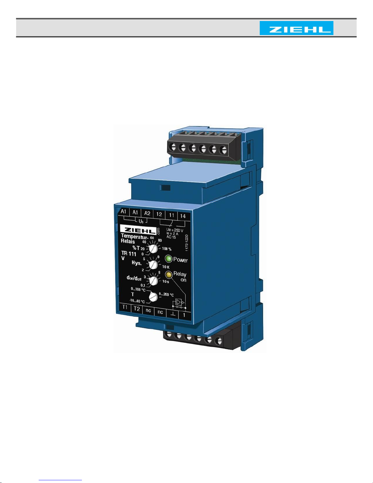
Before switching on make sure that the operational voltage Us of the lateral type plate
and the mains voltage are the same.
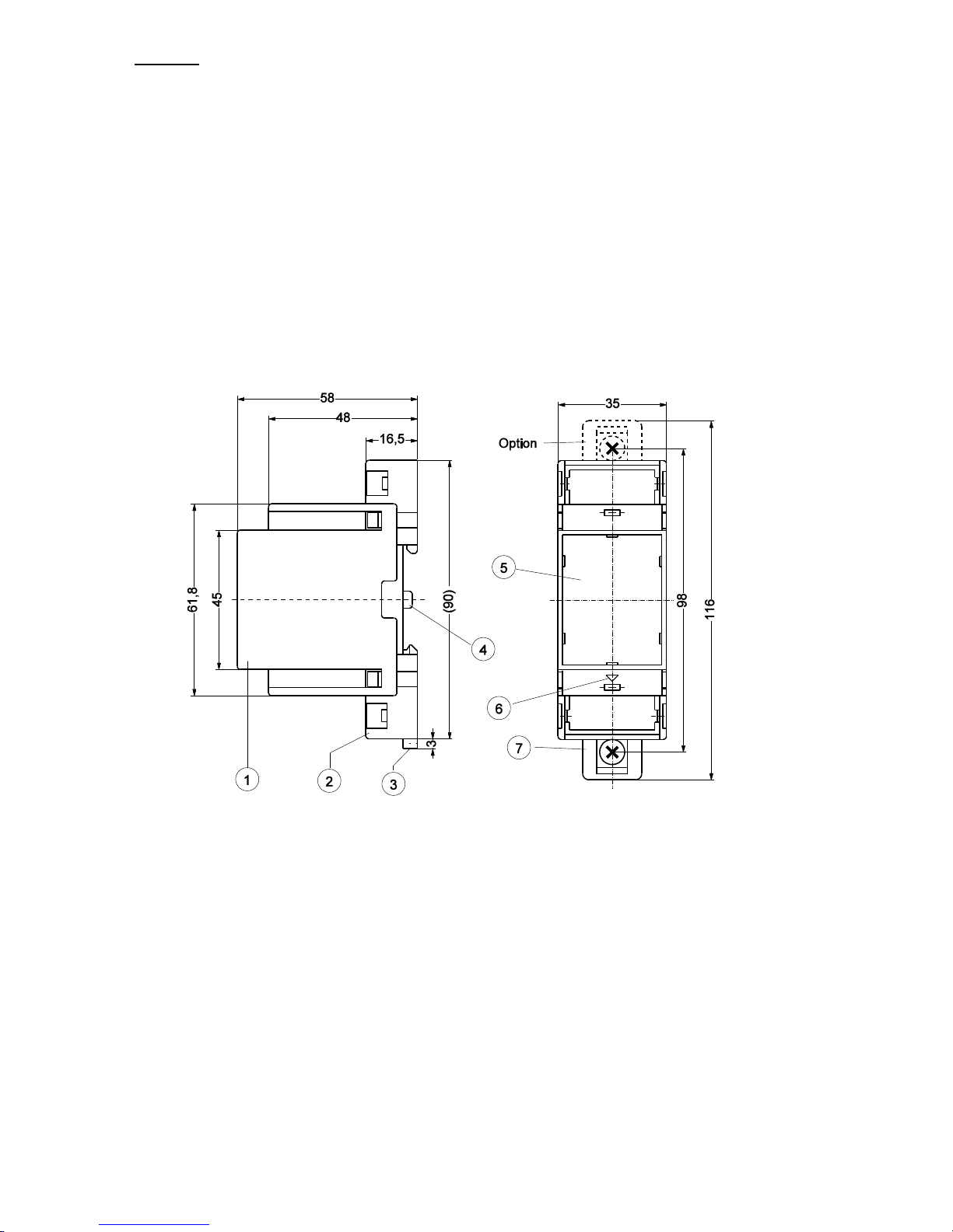
Assembly
mount on 35 mm mounting rail according to EN 60715
wall-mount with 2 x screws M4
connecting wires refer to the wiring diagram.
Putting into operation
•Connect Pt 100 sensor
•Switch on mains voltage
•Relay releases when set temperature is exceeded, the relevant LED is switched on.
Trouble shooting
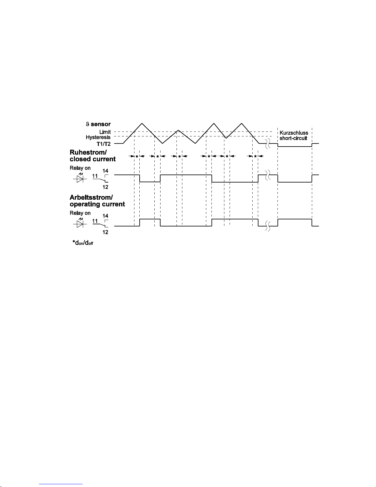
Die Funktion des Gerätes kann mit einem Pt 100 - Simulator oder nach der Widerstands-
tabelle für Pt 100 Sensor EN 60751 überprüft werden. Das Relais schaltet ab bei
überschreiten des eingestellten Grenzwertes, bei Sensorbruch oder Sensorkurzschluss.
(Ruhestrom)

datum / name ) : 27.01.05 Fz Z. Nr.: 1173 0750
Page
5
von 6 Type: TR 111 V
ZIEHL industrie-elektronik GmbH + Co KG, Daimlerstr.13, D-74523 Schwäbisch Hall, Tel.: +49 791 504-0, Fax: -56, e-mail: info@ziehl.de
Technical data
Power Supply (version see lateral type plate)
Supply Voltage Us AC 230 V 50/60 Hz
AC 24 V / DC 20...30 V without potentially separation
Tolerance Voltage Us AC : +10 % / -15 %
Frequency (AC) 48...62 Hz
Power Consumption < 3 VA
Sensor connection Pt 100 EN 60751
Sensor voltage <5 V
Sensor current <3 mA
Short circuit <15 Ω
Limit value
Measuring- ranges 3 or 4 ranges switchable
3 measuring-ranges -10...40 °C / 0...100°C / 0...200°C
Repead error app. 0,5 K
4 measuring-ranges 0...100°C / 100...200°C / 200...300°C / 300...400°C
Repead error app. 0,8 K
Error of setting ±5 K
Temperature-dependence ≤0,05 %/K
Hysteresis adjustable app. 2...10 K
Switching delay don/doff adjustable 0,1 s...10 s
Relay output 1 change-over contact (co)
Switching voltage max. AC 250 V
Switching current max. 5 A
Switching power AC cos = 1 max. 1250 VA (ohmic load)
max. 48 W at DC 24 V
Derating factor at cos 0,7 0,5
Rated operational current AC 15 Ie = 2 A Ue = 250 V
Rated operational current DC 13 Ie = 2 A Ue = 24 V
Ie = 0,2 A Ue = 125 V
Ie = 0,1 A Ue = 250 V
Recommended Fuse 3,15 A gl (slow)
Mechanical Contact Life 1 x 10⁷operations
Electrical Contact Life 1 x 10⁵operations at AC 250 V 5 A
2 x 10⁵operations at AC 250 V 3 A
6 x 10⁵operations at AC 250 V 1 A
Testing conditions EN 50178 / EN 60947
Rated insulation voltage Ui AC 250 V
Insulation EN 60664
Contamination Level 3
Rated impulse voltage 4000 V
Transformer EN 61558
EMC EN 50081-2/EN 50082-2
On period 100 %
max. ambient temperature -20 °C... +55 °C

datum / name ) : 27.01.05 Fz Z. Nr.: 1173 0750
Page
6
von 6 Type: TR 111 V
ZIEHL industrie-elektronik GmbH + Co KG, Daimlerstr.13, D-74523 Schwäbisch Hall, Tel.: +49 791 504-0, Fax: -56, e-mail: info@ziehl.de
Housing Design V2
Mounting height 55 mm
Width 2 TE
Dimensions (H x W x D) mm 90 x 35 x 58
Line connection solid wire 1 x 4 mm2
Stranded wire with insulated ferrules 1 x 2,5 mm2
Protection class housing IP 30
Protection class terminals IP 20
Attachment Mounting 35 mm standard rail according to EN 60715
Optional: Screw mounting M4
Weight approx. 130 g
Subject to technical modifications
Form V2 Dimensions in mm
1Oberteil / cover
2Unterteil / base
3Riegel / bar for snap mounting
4Plombenlasche / latch for sealing
5Frontplatteneinsatz / front panel
6Kennzeichen für unten / position downward
7Riegel bei Wandbefestigung mit Schrauben. Riegelbohrung Ø 4,2 mm / for fixing to wall
with screws, Ø 4,2 mm
This manual suits for next models
1
Table of contents
Other ZIEHL Thermostat manuals
Popular Thermostat manuals by other brands

Vaillant
Vaillant multiMATIC VRC 700 operating instructions

Honeywell
Honeywell CT8611 installation manual

IDEAL
IDEAL Touch user guide

White Rodgers
White Rodgers 1F93-380 installation manual

CHAFFOTEAUX
CHAFFOTEAUX EXPERT HD Assembly and operation instructions

Honeywell
Honeywell SERIES 2000 T7300D user manual