ZKTeco TS200 Series User manual

TS200 Series Tripod Turnstile User Manual
P a g e |1Copyright©2020 ZKTECO CO., LTD. All rights reserved.
Thank you for choosing our product. Please read the instructions
carefully before operation. Follow these instructions to ensure that the
product is functioning properly. The images shown in this manual are
for illustrative purposes only.

TS200 Series Tripod Turnstile User Manual
P a g e |1
About the Manual
This manual introduces the operations of TS200 Series Tripod Turnstile product.
All figures displayed are for illustration purposes only. Figures in this manual may not be exactly
consistent with the actual products.

TS200 Series Tripod Turnstile User Manual
P a g e |2
Document Conventions
Conventions used in this manual are listed below:
GUI Conventions
For Software
Convention
Description
Bold font
Used to identify software interface names e.g. OK,Confirm,Cancel
>
Multi-level menus are separated by these brackets. For example, File > Create >
Folder.
For Device
Convention
Description
< >
Button or key names for devices. For example, press <OK>
[ ]
Window names, menu items, data table, and field names are inside square
brackets. For example, pop up the [New User] window
/
Multi-level menus are separated by forwarding slashes. For example,
[File/Create/Folder].
Symbols
Convention
Description
This implies about the notice or pays attention to, in the manual
The general information which helps in performing the operations faster
The information which is significant
Care taken to avoid danger or mistakes
The statement or event that warns of something or that serves as a
cautionary example.

TS200 Series Tripod Turnstile User Manual
P a g e |3
Table of Contents
1 TECHNICAL SPECIFICATIONS................................................................................................................ 4
2 UNPACKING AND TESTING THE TRIPOD TURNSTILE.....................................................................5
ARM INSTALLATION.................................................................................................................................................... 5
POWER-ON TEST BEFORE INSTALLATION......................................................................................................................5
3 EQUIPMENT INSTALLATION................................................................................................................. 6
INSTALLATION CONDITIONS........................................................................................................................................ 6
CABLING.....................................................................................................................................................................7
INSTALLATION.............................................................................................................................................................8
4 CABLE DIAGRAM......................................................................................................................................9
FUNCTION DESCRIPTION OF THE TURNSTILE CONTROL BOARD.................................................................................... 9
CONNECTION DIAGRAM OF THE ACCESS CONTROLLER.............................................................................................. 10
DIP K1 SWITCH CONFIGURATION.............................................................................................................................10
4.3.1 SETTING THE TURNSTILE OPENING DURATION........................................................................................................ 10
4.3.2 DIRECTION INDICATOR..................................................................................................................................................11
4.3.3 CONTINUE PASSING FUNCTION.................................................................................................................................. 11
4.3.4 ALARM FUNCTION (OPTIONAL)................................................................................................................................... 11
5 EQUIPMENT PRECAUTIONS AND MAINTENANCE........................................................................12
PRECAUTIONS...........................................................................................................................................................12
MAINTENANCE......................................................................................................................................................... 13
6 TROUBLESHOOTING............................................................................................................................. 14
ATTACHMENT 1 FACTORY SETTINGS.......................................................................................................15
ATTACHMENT 2 CONNECTION DIAGRAM OF CONTROL BOARD AND ACCESS CONTROL
PANEL............................................................................................................................................................... 16

TS200 Series Tripod Turnstile User Manual
P a g e |4
Please read this document carefully before installation and using the device.
1Technical Specifications
Input Voltage
AC 100~120V
/200~240V,
50Hz /60Hz
Arm Length (mm)
500
Operating Environment
Indoor and
Outdoor
(shelter)
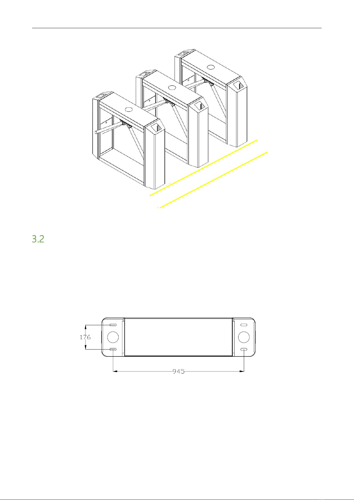
Dimension(mm) (Figure 1)
L = 1200, W = 280, H = 980
Operating Temperature
-28ºC ~ 60ºC
Package Size (mm)
L = 1275, W = 370, H = 1063
Operating Humidity
5% ~ 85%
Flow Rate
Max 30 passages / minute
Input Control Signal
Dry contact
Rated Power
18 W
Figure 1

TS200 Series Tripod Turnstile User Manual
P a g e |5
2Unpacking and Testing the Tripod Turnstile
Arm Installation
In order to prevent the arm from damaging during transportation, the arm will not be initially
installed to the devices.
Installation procedure
Put the arm kit into the hole of cabinet; make sure the screw holes match with mechanism core, then
tighten 3 hex screws, as shown in Figure 2-1.
Figure 2-1
Power-on Test before Installation
1. Please make sure that the power requirements are strictly met to avoid permanent damages to
the unit. Input voltage: AC 100~120V /200~240V.
Note: The tripod turnstile must be connected to the ground (earth).
2. Power on and wait 30s for the tripod turnstile to finish the self-check program.
3. Lift the arms manually, as shown in Figure 2-2.
4. Check whether the tripod turnstile and the LED indicators work properly.
If there is any problem, please contact the supplier.
There is a power
switch in the side
direction of this
power supply.
Earth wiring terminal
Lift upwards

TS200 Series Tripod Turnstile User Manual
P a g e |6
Figure 2-2
3Equipment Installation
Installation Conditions
The equipment must be installed on concrete ground, ensuring that expansion bolts can be secured
firmly.
You are suggested to install an assistant framework or fence to form a passageway, as shown in
Figure 3-1.
Figure 3-1
Notes:
1. When installing the tripod turnstile against the wall, please reserve a distance of at least 100 mm
in order to open the cover for future adjustment and maintenance.
2. The spare space from the end of the arm shall not be greater than 80 mm (see Figure 3-1).
3. You are also recommended to set a warning line for card swiping (see Figure 3-2). The warning
line prompts users to swipe cards in a particular area, which would greatly reduce the probability of
equipment failure caused by improper operations.
TS200 Series Tripod Turnstile User Manual
P a g e |7
Figure 3-2
Cabling
There are inlets in the bottom plate for cabling, as shown in Figure 3-3. Units of all data is millimeter.
Power supply and communication wire should go through the inlet. Cable protection covers are
suggested to use if it is surface mounted.
Warning: The tripod turnstile must be connected to the ground (earth); there is wiring interface
near the power switch.
Figure 3-3
TS200 Series Tripod Turnstile User Manual
P a g e |8
Installation
1. Drill holes.
Drill holes according to the locations of holes as shown in Figure 3-3.
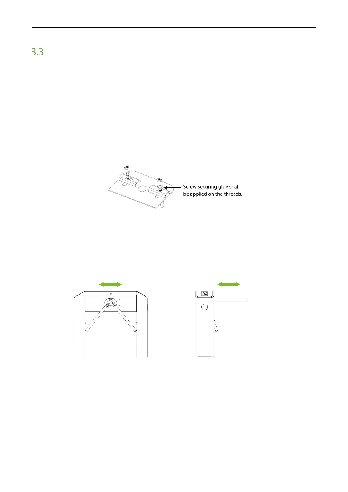
2. Fix the mounting plate to its original position.
Place the mounting plate properly, then apply screw securing glue on the surface and threads of the
expansion bolts, install four expansion bolts to secure the mounting plate, and use a horizontal ruler
to test the levelness of the mounting plate. If the mounting plate is not levelled, adjust it with the
gaskets provided. Note that all the four expansion bolts must be installed properly, as shown in
Figure 3-4.
Figure 3-4
3. Install the turnstile on the mounting plate and tighten the screws. Apply screw securing glue
before using and putting gaskets on the screws to adjust the direction of the turnstile. If the
tripod turnstile is not levelled, you can place gaskets to adjust, as shown in Figure 3-5.
Installation levelness Installation levelness
Figure 3-5

TS200 Series Tripod Turnstile User Manual
P a g e |9
4Cable Diagram
Function Description of the Turnstile Control Board
If you are using standard device that without RFID or Fingerprint reader, you need to connect access
control system to the main board, please check the content in this chapter carefully.
Turnstile control board’s diagram as shown in Figure 4-1.
Figure 4-1
TS200 Series Tripod Turnstile User Manual
P a g e |10
Note: The third party access control system lock relay trigger time should be 1 second or less than 1
second.
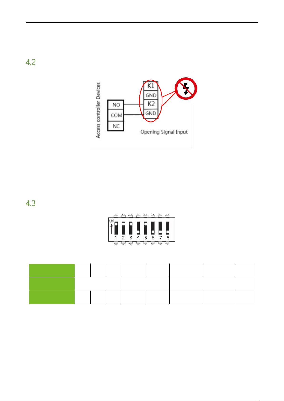
Connection Diagram of the Access Controller
Figure 4-2
Note: The lock relay duration of access controller device needs to be set to 1s. Forbidden using
electrically charged objects to connect to the port of Opening Signal Input, otherwise will damage
the control board.
DIP K1 Switch Configuration
Figure 4-3
Pin
1
2
3
4
5
6
7
8
Function Setting
Opening Duration
Direction Indicator
Continue Passing Function
Alarm
Default
1
1
1
0
1
0
0
0
0=ON 1=OFF
4.3.1 Setting the Turnstile Opening Duration
Opening duration refers to the period of time from opening to closing once the turnstile receives an
opening signal. In the DIP switch, number 1, 2, and 3 are used for duration settings. It can be set to
different values from 5s to 60s according to the following chart.

TS200 Series Tripod Turnstile User Manual
P a g e |11
Bit Setting
Duration
Bit Setting
Duration
111
5s
011
30s
110
10s
010
40s
101
15s
001
50s
100
20s
000
60s
Note: The turnstile’s opening duration is set to 5s by default.
4.3.2Direction Indicator
It is to indicate whether people can pass through the gate. The green arrow means passing is
allowed while the red cross "X" means that passing is prohibited. The indicator status can be set with
number 4 and 5 in the DIP switch. The descriptions of the bit settings are as follows:
11 = Passing is allowed in both directions.
10 = One-way forbidden; right passing is allowed.
01 = One-way forbidden; left passing is allowed.
00 = Both ways forbidden.
4.3.3Continue Passing Function
With the “Continue Passing” function, the turnstile could remember at most 20 swipes of one card at
one time and allows up to 20 people to pass so they don’t have to swipe card each time. This
function can be enabled or disabled with number 6 in the DIP switch. The descriptions of the bit
settings are as follows:
In the DIP switch, number 6 is used to enabled or disabled the Continue Passing Function; number
7 is used to set the initial value of Continue Passing Function.
Number
6
Number
7
Function
Opening Duration
0
Disabled
Disabled Continue Passing
Function
Please refer to section 4.3.1 Setting the
Turnstile Opening Duration.
1
1
Enabled Continue Passing
Function
The initial value is 16s, and the Opening
Duration = 16 + (N -1) * 6.
0
The initial value is 8s, and the Opening
Duration = 8+ (N -1) * 6.
4.3.4Alarm Function (Optional)
In the DIP K1 switch, number 8 is used to enabled or disabled the Alarm Function.
1= enabled

TS200 Series Tripod Turnstile User Manual
P a g e |12
0= disabled
Note: Please set to 0 when working normally, that is to say that Alarm Function is disabled.
5Equipment Precautions and Maintenance
Precautions
1. It is recommended to purchase additional accessories to use the product outdoors.
1) You may install cooling fans for the equipment if the working temperature is often above
50 ºC.
2) If the temperature is around or below -30ºC, you are recommended to install a heating
plate for the equipment. You might need to turn the power on multiple times to let the
device automatically heat up through the self-check program.
3) The service life of this equipment may be shortened if it works outdoors in coastal areas or
a region prone to acid rain.
2. If the power and signal cables are connected properly, this equipment can be immersed under
water at a depth of 250 mm, but it must not be powered on when it is immersed in water.
3. It is highly recommended to set a warning card-swiping line to remind passers-by to correctly
swipe cards at a reasonable distance from the device to prevent passers-by from being
squeezed.
4. It is recommended to place a warning sign at a conspicuous position, and prompt: "Please
swipe your card outside the warning line and pass in order. Thank you!”
The maximum stress tolerance of the tripod turnstile's arms
Please note that the maximum tolerance at the center and the ends of the arm is 80kg and 40kg,
respectively (See Figure 5-1). When the impact force on the tripod turnstile reaches the designed
limit, the arms will break down first to ensure that the body of the equipment is not damaged and
the passer-by is not injured.
Figure 5-1
In case of emergencies
Maximum stress
tolerance: 80 kg
Maximum stress
tolerance: 40 kg
TS200 Series Tripod Turnstile User Manual
P a g e |13
This equipment is designed to drop the arms automatically if there is power failure thus people can
pass freely. Also, there is an interface on the turnstile control board connecting with an emergency
switch (J6 Drop Arm) which keeps the tripod turnstile open in case of emergencies. Please lift the
arms manually after at least 6 seconds after power restoration.
Maintenance
Forming maintenance consciousness
The tripod turnstile needs to be maintained regularly and repaired once it is damaged. It is
recommended placing warning signs at conspicuous positions for alerting every passersby to pass
carefully and in good order. Reasonable maintenance consciousness helps to guarantee long-term
usage of the tripod turnstile.
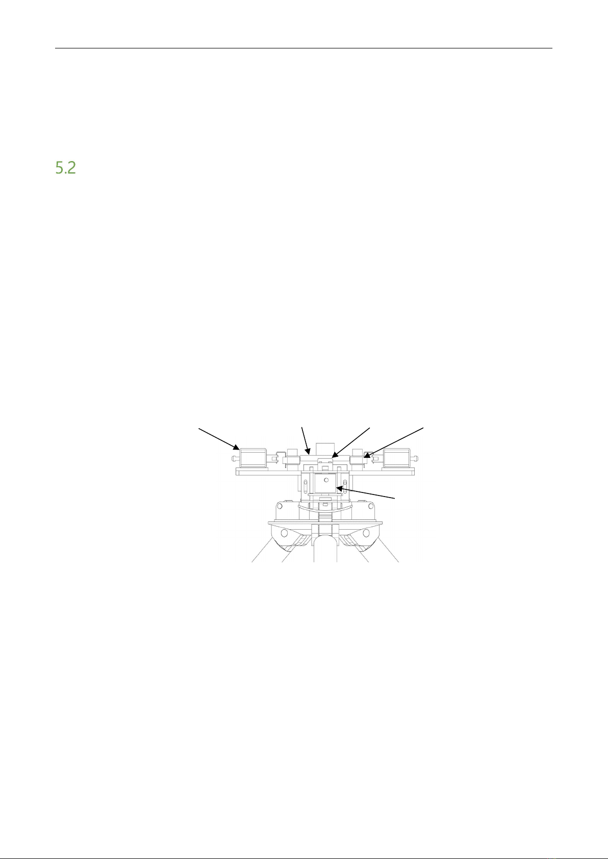
Regular maintenance
Cleaning and protection liquid dedicated for stainless steel are recommended to wipe the outer
shell of the equipment regularly. The tripod turnstile used outdoors or in an environment with lots
of dust must be maintained at least once a year, for example, clean up the dust and add appropriate
lubricating oil to the disk wheel. Please note that regular maintenance should only be performed
after power-off, as shown in Figure 5-2.
Turnstile-opening Solenoid
Lock Rod
Drop-arm
Solenoid
Position Sensor
Disk Wheel
Figure 5-2

TS200 Series Tripod Turnstile User Manual
P a g e |14
6Troubleshooting
Symptom
Troubleshooting
The indicator is not lit when the
equipment is powered on.
It may be caused by the power supply or circuit.
Check whether the connection cable and power cable are
damaged, or whether the wiring is loosed.
The arms of the tripod turnstile cannot
be lifted manually after the equipment
is powered on.
It may be caused by the problem of related components or
drop-arm solenoid.
Check whether the drop-arm solenoid is operating, and
check the working status of the solenoid, as shown in Figure
5-2.
The tripod turnstile does not grant an
access after successful authentication.
It may be caused by lack of permission or a circuit problem.
1. Check whether the user has the permission to pass.
2. Use a multimeter to check whether the NO and COM
ports of the access control system have a relay signal
output.
3. Short-circuit the ports "K1, GND" and "K2, GND"; if the
turnstile is successfully opened, the controller is not
normal.
In this case, please refer to Attachment 2 Connection
Diagram of Control board and Access Control Panel to
check the cable connection of the controller.
The turnstile allows people to
continuously passing one-way side.
1. Check the turnstile-opening solenoid.
2. Check if the access controller “Lock driving duration” is
set to 1s.
3. Check whether the turnstile-opening solenoid is
operating and check whether something is stuck at the
turnstile-opening solenoid, as shown in Figure 5-2.

TS200 Series Tripod Turnstile User Manual
P a g e |15
Attachment 1 Factory Settings
No.
Function
Default
1
Lock Driving Duration
5s
2
Door Sensor
None
3
Verification Interval
1s
4
Controller
Communication
TCP/IP: 192.168.1.201
5
Turnstile Opening
Duration
5s
6
Passing Direction
Indicator
Passing is allowed in both
directions
7
Continue Passing
Function
Disabled
8
Alarm Function
Disabled
Note: The Lock Driving Duration is 5 seconds by default. Please set it to 1 second. Do not connect
an electrically charged objects to any ports of Opening Signal Input, otherwise it will damage the
control board.

TS200 Series Tripod Turnstile User Manual
P a g e |16
Attachment 2 Connection Diagram of Control Board and
Access Control Panel
Warning: This is a class A product. In a domestic environment, this product may cause radio
interference so that the user may have to take adequate additional measures.
Table of contents
Other ZKTeco Camera Accessories manuals


Popular Camera Accessories manuals by other brands


Sony
Sony FDA-V1K operating instructions

EnerSys
EnerSys DataSafe HX Installation, operation and maintanance manual

Moog
Moog FusionDome FDW75C8N Installation and operation instructions

VERSATIVTECH
VERSATIVTECH Circuit Breaker Finder instruction manual
Pixel
Pixel ROOK instruction manual

KINGJOY
KINGJOY KINGJOY-VT-1500 user manual