Page 7
ENGLISH
Zodiac FloPro™E3 3-Speed Variable Pump |Installation & Operation Manual
Section 4. Operation
4.1 Start-up
CAUTION
Never run the pump without water. Running the
pump “dry” for any length of time can cause severe
damage to both the pump and motor and will void
the warranty.
If this is a new pool installation, make sure all piping
is clear of construction debris and has been properly
pressure tested. The lter should be checked for
proper installation, verifying that all connections and
clamps are secure according to the manufacturer’s
recommendations.
WARNING
To avoid risk of property damage, severe personal
injury or death, verify that all power is turned off
before starting this procedure.
1. Release all pressure from the system and open
the lter pressure release valve.
2. Depending on the location of the pump, do
one of the following:
- If the pump is located below the water level of
the pool, open the lter pressure release valve
to prime the pump with water.
- If the pump is located above the water level
of the pool, remove the lid and ll the basket
with water before starting the pump.
3. Prior to replacing the lid, check for debris
around the lid o-ring seat. Debris around the
lid o-ring seat will cause air to leak into the
system and will make it difcult to prime the
pump.
4. Hand-tighten the lid to make an air tight seal.
Do not use any tools to tighten the lid: hand-
tighten only. Make sure all valves are open
and the unions are tight.
5. Restore power to the pump.
6. Once all the air has left the lter, close the
pressure release valve.
7. The pump should prime. The time it takes
to prime will depend on the elevation and
length of pipe used on the suction supply
pipe. See Section 3.1.3.3, Installation
Recommendations, for proper elevation and
pipe size.
8. If the pump does not prime and all the
instructions to this point have been followed,
check for a suction leak. If there is no leak,
repeat Steps 2 through 7.
9. For technical assistance, call Zodiac Technical
Support at 1.800.688.152.
4.2 Operational Controls
IMPORTANT
Due to an undervoltage protection placed in the
software to protect the internal electronics, there
may be an error during motor startup. If this
situation occurs, simply let the motor sit without
power for approximately 3-5 minutes to allow the
capacitors to completely drain before restarting the
motor.
NOTE
- If power is removed, motor will return to the last
speed selected when power is restored.
- Motor will remember ON/OFF states.
- If there is a fault, Error LED will blink. See Section
6 more information on fault codes.
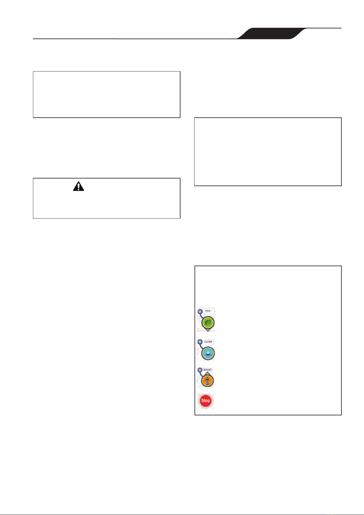
Normal Operation Mode
- For LOW speed, the LED will flash when selected
until the priming cycle is complete. Once complete,
the LED will be steadily lit.
- For MEDIUM speed, , the LED will flash when selected
until the priming cycle is complete. Once complete,
the LED will be steadily lit.
- For HIGH speed, , the LED will flash when selected
until the priming cycle is complete. Once complete,
the LED will be steadily lit.
- To turn OFF (LED will flash when selected)
On start up, the LED for the selected speed will flash for
approximately 1 minute as the pump goes through a priming
cycle. When the cycle is complete, the LED for the selected
speed will be steadily lit.
Figure 3. Normal Operation Mode Controls