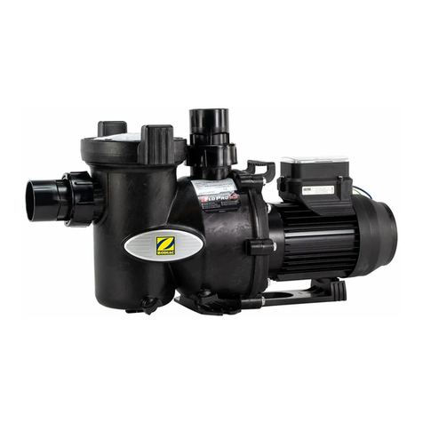
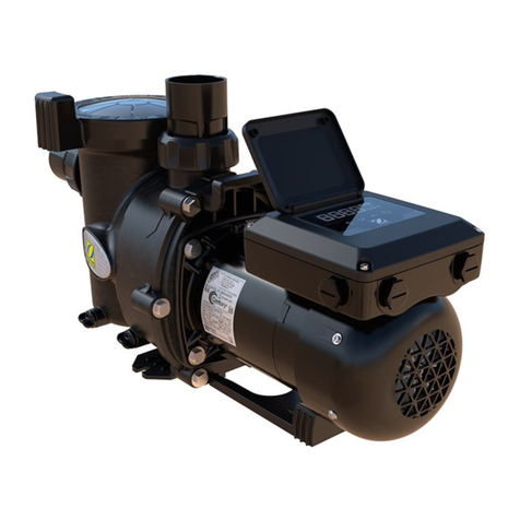
Zodiac FloPro e3 User manual

H0538700.C - 2017/01
More documents on:
www.zodiac-poolcare.com
Instruc ons for installa on and use - English
Filtra on pump
Transla on of the original instruc ons in french EN
FloPro™ e3


1
WARNINGS
• Failure to respect the warnings may cause serious damage to the pool equipment or cause serious
injury, even death.
• The appliance is intended to be used only for swimming pools and spas; it must not be used for any
purpose other than that for which it has been designed.
• It is important that the appliance is operated by people who are competent and qualifi ed (both physically
and mentally), a er having read the instruc ons for use. All persons not mee ng these criteria must
not approach the appliance in order to avoid exposure to dangerous elements.
• Keep the appliance out of the reach of children.
• The appliance must be installed according to the manufacturer’s instruc ons and in compliance with
local standards. The installer is responsible for installing the appliance and for compliance with na onal
installa on regula ons. Under no circumstances may the manufacturer be held liable in the event of
failure to comply with applicable local installa on standards.
• Incorrect installa on and/or use may cause serious damage to property or serious injuries (possibly
causing death).
• All equipment, even postage and packing paid, travels at the risks and perils of the recipient. The
la er shall issue reserves in wri ng on the carrier's delivery slip if damage is detected, caused during
transport (confi rma on to be sent to the carrier within 48 hours by registered le er). In the event that
an appliance containing coolant has been turned on its side, men on your reserva ons in wri ng to
the carrier.
• If the appliance suff ers a malfunc on, do not try to repair the appliance yourself. Instead contact a
qualifi ed technician for service.
• Refer to the warranty condi ons for details of the permi ed water balance values for opera ng the
appliance.
• Defea ng, elimina ng or shun ng any of the safety that may be a part of the device automa cally voids
the warranty, as does the use of unauthorized, third party replacement parts.
• Do not spray insec cide or any other chemical (infl ammable or non-infl ammable) in the direc on of the
appliance, as this may damage the body and cause a fi re.
• The power supply to the appliance must be protected by a dedicated 30 mA residual current device,
complying with the standards and regula ons in force in the country in which it is installed.
• Do not use and extension cord to plug the appliance into; plug it directly into a proper wall socket or
outlet.
• Before carrying out any opera ons, check that:
-The voltage indicated on the appliance informa on plate corresponds to the mains voltage,
-The power grid is adapted to the power requirements of the appliance, and is properly grounded.
-The plug (where applicable) is suitable for the socket.
• In the event of abnormal opera on or the release of odours from the appliance, turn it off immediately,
unplug it from its power supply and contact a professional.
• Before any access to the appliance for any required service or maintenance, ensure that it is switched
off and disconnected from the power supply.
• Do not disconnect and reconnect the appliance to the power supply when in opera on.
• Do not pull on the power cord to disconnect it from the power supply.
• Do not a empt to carry out any service or maintenance with wet hands or while the appliance is wet.
• Clean the terminal board or the power supply socket before connec on.
• For any component or sub-assembly containing a ba ery: do not recharge or dismantle the ba ery, or
throw it into a fi re. Do not expose it to high temperatures or direct sunlight.
• In stormy weather, unplug the appliance to prevent it from suff ering lightning damage.
• Do not immerse the appliance in water (with the excep on of cleaners) or mud.
• This appliance is compa ble with all types of water treatment used in swimming pools. Refer to the
Zodiac® warranty condi ons for details of the permi ed water balance values.
• Never run the pump dry or out of the water as this will invalidate the warranty.
Recycling
This symbol means that your appliance must not be thrown into a normal bin. It will be selec vely collected
for the purpose of reuse, recycling or transforma on. If it contains any substances that may be harmful to the
environment, these will be eliminated or neutralised.
Contact your retailer for recycling informa on.
EN

2
CONTENTS
❶ Specifi ca ons 3
1.1 I Descrip on 3
1.2 I Technical specifi ca ons 3
1.3 I Dimensions and marking 4
1.4 I Performance curves 4
❷ Installa on 5
2.1 I Selec ng the loca on 5
2.2 I Hydraulic connec ons 6
2.3 I Power connec ons 7
❸ Use 8
3.1 I Opera ng principle 8
3.2 I User interface presenta on 8
3.3 I Opera on 8
3.4 I Addi onal user func ons 9
❹ Maintenance 10
4.1 I Winterising 10
4.2 I Servicing 10
❺ Troubleshoo ng 11
5.1 I Appliance behaviour 11
5.2 I Error codes 12
• Before handling the appliance, it is essen al that you read this installa on and user manual,
as well as the "warnings and warranty" booklet delivered with the appliance. Failure to do so
may result in material damage or serious or fatal injury and will void the warranty.
• Keep and pass on these documents for later viewing throughout the appliance's service life.
• The distribu on or modifi ca on of this document in any way is prohibited, without prior
authorisa on from Zodiac®.
• Zodiac® is constantly developing its products to improve their quality. The informa on
contained herein may therefore be modifi ed without no ce.
Tip: to make it easier to contact your retailer
• Write down your retailer's contact details to help you fi nd them more easily and fi ll in the "product"
informa on on the back of the manual; your retailer will ask you for this informa on.

3
❶ Specifi ca ons
1.1 I Descrip on
1.2 I Technical specifi ca ons
Unit FloPro™ e3
Opera ng water temperature 2 to 35°C
Nominal voltage of motor 230 Vac-50 Hz
Motor power - phases 1P
Admissible varia on in motor voltage ± 10% (during opera on)
Motor output power (P2) HP 1
W 750
Maximum power at motor input (P1) W 1000
Maximum motor amperage A6.5
Cable cross-sec on
mm² 3x1.5
Lug
type 3G1.5
Electrical protec on A 10
Primary protec on 8A fuse 32x6.3mm
Motor protec on ra ng IPX5
Maximum pump fl ow m³/h 22.4
Pump fl ow rate at 10 meters of head m³/h 16.3 (at 2850 RPM)
Maximum pump pressure mH²O19.1
bar 1.9
Pump pipe connec on 2” threaded suc on/discharge
Ø63/50 mm union couplings
Maximum pump salinity 6g/L (6000 ppm)
Pipes Maximum suc on rate at
1.8 metres/second Maximum discharge rate at
2.4 metres/second
Ø 50 mm 14 m³/h 19 m³/h
Ø 63 mm 20 m³/h 27 m³/h
AFloPro™ e3 pump
BUnion connec on Ø63/50 mm x2
CPump base
EN

4
1.3 I Dimensions and marking
: Pool water inlet
: Pool water outlet
: Pre- fi lter cover
: User interface
: Pump motor
: Drain
Front Side
Weight: 10 Kg
1.4 I Performance curves
Manometric
head
Flow rate

5
❷ Installa on
2.1 I Selec ng the loca on
• The pump must be installed:
- before the fi lter, a hea ng and/or water treatment system,
- at a minimum distance of 3.5 metres from the edge of the pool, to avoid any water being sprayed onto the
appliance. Some standards allow for other distances. Refer to the regula ons in eff ect in the country of installa on.
- ideally 30 cm below the water level,
- out of an area subject to fl ooding, or on a base with drainage,
- in a ven lated area to allow the pump and motor to cool.
• The pump must not be installed:
- in an area subject to splashing or rain.
- more than 1 m above the water level.
- near a heat source or source of fl ammable gas.
- in an area that cannot be cleaned or kept free of leaves, dry foliage, and other poten ally fl ammable items.
• Easy access is required for maintenance work on the appliance.
• Place on a stable, level and solid surface (e.g. concrete fl oor).
• If necessary, use the bases (2 types of base, not supplied, available as an op on) to raise the pump to the level of the
exis ng pipes.
• Anchor the pump to the ground using the adapted founda on bolt.
EN

6
2.2 I Hydraulic connec ons
• Respect the direc on of hydraulic connec on (see § “1.3 I Dimensions and marking”).
• Choose the dimension of the pipes according to the size of the pool and respec ng the hydraulic rules which apply in
the country of installa on.
• Performance curves are available in § “1.4 I Performance curves” for the pipe dimensions.
• For hydraulic connec ons, use the Ø63/50 mm union couplings via bonding (provided) or the 2’’ threaded PVC
couplings directly screwed onto the pump.
• Fit a check valve if the fi lter is installed above the water level.
• Fit suc on and discharge isola on valves if the pump is installed below the water level.
• To help prevent diffi culty in priming, install the suc on pipe without high points, which can trap air.
• Check that the hydraulic correc ons are correctly ghtened and that there are no leaks.
• The pipes must be supported to prevent any risk of breakage due to the weight of the water.
: pump
: fi lter
: hea ng system
: water treatment system
• Use as few elbow joints as possible. If there needs to be more than 10 elbow joints on the hydraulic circuit, increase
the pipe diameter.
• Suc on pipe length = 4 x Ø • Suc on pipe too short
• Risk of cavita on
• Air reten on
• Risk of incorrect pre- fi lter fi lling

7
2.3 I Power connec ons
• Before any work on the appliance, you must disconnect the electricity supply to avoid the risk
of electric shock which may cause material damage, serious injury or even death.
• Only a qualifi ed and experienced technician is authorised to carry out any service, including
cabling work within the appliance or to replace the power cord.
• To prevent overhea ng of the terminal board, which could create a fi re hazard, check that all
terminals have been properly ghtened. Loose terminals will void the warranty.
• The appliance must be connected to the earth.
• Any unsuitable electrical connec on will invalidate the warranty.
• The appliance's electrical supply must be provided through a protec on and circuit breaking device (not supplied)
complying with the standards and regula ons in force in the country in which it is installed.
• Electrical protec on: by circuit breaker (D curve), with a 30 mA dedicated diff eren al circuit breaker (circuit breaker
or switch) at the head of the line.
• The power supply must correspond to the voltage indicated on the appliance's informa on plate.
• The power cord must be insulated and protected against abrasions and damage.
• Use the gland to pass the power cord into the appliance.
• The appliance and the swimming pool and any other electrical equipment must be connected to the earth.
2.4.2 Power supply and clock
Connect the pump to the contactor downstream of the swimming pool switch box's fi ltra on clock.
The fi ltra on unit clock directly controls the pump's electricity supply, which then starts.
2.4.3 Connec ng the motor's power supply
• Open the electrical connec on box by unscrewing the 3 screws on the user interface and l ng it to the side (pay
a en on to the wires underneath).
• Disconnect and remove the factory test power wires exi ng the connec on box where necessary.
• Run the power cord through the gland and connect it to the terminals in accordance with the power supply:
230 Vac - 50 Hz power supply = connec on to the (earth) and N-L terminals.
• Close the electrical connec on box, making sure that the seal is on place and ghten the 3 screws.
EN

8
❸ Use
3.1 I Opera ng principle
The fi ltra on pump forms the core of the pool and is essen al as it is used to circulate water through the pool’s diff erent
components, in par cular the fi lter.
Its motor drives the turbine in rota on, which drives the water. The large strainer of the pre- fi lter collects major debris
to prevent the fi lter from becoming clogged too quickly or from becoming damaged.
3.2 I User interface presenta on
Symbol Designa on
Key "ECO" speed ac va on
Speed reduc on in se ng mode
LED Flashing: in priming mode (approx. 2 minutes on start-up)
Fixed: speed in opera on
Key "CLEAN" speed ac va on
Recording of the current se ng (press for 10 seconds)
LED Flashing: in priming mode (approx. 2 minutes on start-up)
Fixed: speed in opera on
Key "BOOST" speed ac va on
Speed increase in se ng mode
LED Flashing: in priming mode (approx. 2 minutes on start-up)
Fixed: speed in opera on
Key Shutdown of the speed during opera on
LED Flashing: pump stopped, powered up
Fixed: pump in opera on
LED The number of fl ashes indicates the error in progress
3.3 I Opera on
• To prevent against any risk of explosion that may cause material damage, serious injury or
even death, make sure that the hydraulic circuit is free of any debris or blockage and is not
subject to excessive pressure.
• Never run the pump "dry" as this may damage it.
• The pre- fi lter strainer cover must be closed by hand (do not use any tools).
• Check that the hydraulic connec ons are correctly ghtened.
• Check that the pump is stable and level.
• The hydraulic circuit must be bled and not contain any foreign bodies.
• The pump pre- fi lter strainer cover must be correctly closed (by hand) and its gasket clean and in place.
• Check that the valves are open.
• Start up the pump by ac va ng a speed. The pump always starts in "priming" mode (2850 rpm for approx. 2 minutes).
• The pump is self-priming. However, you are strongly recommended to fi ll the pre- fi lter strainer with water before
star ng it up for the fi rst me to facilitate the procedure.
• The pump has a priming capacity up to 3 metres above the swimming pool water level and at sea level eleva on (if
the hydraulic circuit is perfectly sealed).
• Bleed any air present in the fi ltra on circuit using the bleed normally present on the fi lter (refer to the swimming pool
fi lter's manual).
• Check that there are no leaks on the hydraulic circuit.

9
3.4 I Addi onal user func ons
3.4.1 Using speeds
Speed Keys to start the speed Default speed
"ECO" speed 1400 rpm
"CLEAN" speed 2150 rpm
"BOOST" speed 2850 rpm
"PRIMING" speed Automa c at start-up 2850 rpm for 2 minutes
• When the pump is running, it displays the opera ng speed and an LED lights up above the key which
corresponds to the speed.
If the mains supply is disconnected (manually or via the fi ltra on clock) the pump will restart at the
last speed ac ve.
3.4.2 Modifying the speed confi gura on
- the speed you want to modify must be opera ng,
- press the key that corresponds to this speed for 5 seconds (the corresponding LED must fl ash).
- press or un l you reach the speed you want (increments of 50 rpm).
- Press and hold for 10 seconds to save.
3.4.3 Pump shutdown
• Press .
3.4.4 Pump reset
You may reset the pump to return it to "factory" confi gura on:
- make sure that the pump is powered up but stopped ("OFF" is displayed on the screen).
- press + + for 5 seconds un l the 3 corresponding LEDs fl ash once.
- release the keys: the pump is now reset.
EN

10
❹ Maintenance
4.1 I Winterising
• The pump must be fully wintered in the event of a risk of frost or extended electrical
disconnec on. If the pump freezes it may cause severe damage and invalidate the warranty.
• To avoid damaging the appliance with condensa on, do not fully cover it.
• If the pump is posi oned below the water level, close the isola on valves at suc on and discharge.
• Drain the pump (using the 2 bleed screws) and the hydraulic circuit, following the swimming pool manufacturer's
instruc ons.
• Remove the 2 bleed screws and keep them to reinstall them when the pump is put back into opera on.
• You are recommended to disconnect the electrical power cable then unscrew the hydraulic connectors to store the
pump in a dry place away from frost.
• Store the pump in a dry environment at a temperature that varies as li le as possible to prevent condensa on which
would damage the pump.
4.2 I Servicing
• It is recommended that the appliance undergo general servicing at least on a yearly basis
to ensure proper opera on, maintain performance levels and poten ally prevent certain
failures. These opera ons are carried out at the user's expense and certain opera ons must
be performed by a technician.
4.2.1 User maintenance
• Make sure that the pump and electrical compartment contain no foreign bodies.
• Clean the outside of the appliance, do not use solvent-based products.
• Clean the pre- fi lter strainer, the cover and the gasket regularly.
• Check that the pre- fi lter strainer is correctly in place, or it may prevent the cover from closing fully.
4.2.2 Maintenance to be carried out by a qualifi ed technician
• Check the connec on of the metal masses to the earth.
• Check that the electrical cables are correctly ghtened and connected and that the switch box is clean.
• Check that the user interface is correctly connected.

11
❺ Troubleshoo ng
• If a problem occurs, before you contact your retailer, please carry out these few simple checks
using the following tables.
• If the problem con nues, contact your retailer.
• : Ac ons to be performed by a qualifi ed technician only
5.1 I Appliance behaviour
The pump does not start
/ the motor does not
turn.
• Filtra on outside of a scheduled opera ng range (“Auto” mode). Check the fi ltra on
clock se ngs.
• Faulty user interface fuse, replace.
• Electric power cut. Check the circuit breaker(s).
• Check the connec on between the power cable and the motor terminals.
• Check that the user interface cable is not damaged.
• The "error" light fl ashes, see § “5.2 I Error codes”
• Check that the motor sha rotates freely. Check that there is no debris in the pre- fi lter
strainer.
• If debris remains, remove the pump to access the turbine.
The pump doesn’t prime
/ air can be seen in the
pre- fi lter strainer.
• Check the posi on of all valves in the hydraulic circuit.
• Air is stuck in the circuit, drain the hydraulic circuit (drain screw on the fi lter).
• The pool’s water level is too low, air is being sucked into the circuit, fi ll the pool.
• The gasket of the pre- fi lter strainer lid is defec ve, check the condi on of the gasket
and the correct air- ghtness of the lid.
Low fl ow rate / low fi lter
pressure
• Pre- fi lter basked full of debris: clean.
• Air leak in the circuit. Check all ghtening torques.
• The turbine and the pump diff user are blocked or worn, replace.
• The diff user seal is worn, replace.
Low fl ow rate / high fi lter
pressure
• The fi lter is clogged. Wash the fi lter (or the cartridge depending on the case).
• Check the posi on of all valves in the hydraulic circuit.
Pump making a lot of
noise
• Air leak or cavita on in the suc on piping. Check the posi on of the valves and adjust
where necessary.
• Pump incorrectly posi oned on the ground. Check that it is res ng in a fl at posi on on
a hard, horizontal ground. Use an -vibra on studs where necessary.
• A foreign body is present in the pre- fi lter strainer.
• A foreign body is present in the pump body (in this case, the pump must be
removed).
Leak between the pump
body and the motor • The mechanical lining is damaged or defec ve, replace
The pump heats up and
switches off
• The motor is overhea ng due to too li le ven la on. Check that there is enough clear
space around the motor.
• There is an electrical fault. Check the power connec ons and check the mains
voltage, which must not vary.
There is no damage to
the user interface
• The cable(s) is(are) damaged or poorly connected in the user interface housing; check
the condi on of these cables.
EN

12
5.2 I Error codes
Number of
fl ashes Malfunc on Possible causes Solu ons
1User interface is
defec ve • The user interface resets
itself constantly • Check the electrical
connec ons inside the user
interface housing.
• Replace the motor - interface
assembly if necessary.
2Network sub-
voltage • The network voltage has
fallen below 180VCA. • The interface will reset when
the voltage rises over 209VCA
again for at least 6 seconds
3 temperature • Motor temperature too high
(+100°C)
• Motor temperature too low
(-20°C)
• Wait un l normal temperature
condi ons return and restart
the pump.
4 Surge ac va on • The surge protec on has
been ac vated • Check the electrical supply.
• Restart the pump.
5 Network
overvoltage • The voltage exceeds 269VCA • The interface will reset when
the voltage returns to a
normal value.
6Motor sha jammed • Motor start-up impossible
• The motor has stopped • Break the pump circuit
and check that no debris is
blocking the turbine (remove
the pre- fi lter screen).
• Check that there is no debris
blocking the rear fan.
7Automa c
verifi ca on • At least one of the automa c
tests failed on start-up or
during opera on
• Break the pump circuit then
reconnect it to reset it.
8 Motor fault • At least one of the phases is
disconnected • Check the electrical
connec ons inside the user
interface housing.

ZODIAC® is a registered trademark of Zodiac Internaonal, S.A.S.U., used under license.
Zodiac Pool Care Europe - BP 90023 - 49180 St Barthélémy d’Anjou cedex - S.A.S.U. au capital de 1 267 140 € / SIREN 395 068 679 / RCS PARIS
Votre revendeur
Your retailer
Modèle appareil
Appliance model
Numéro de série
Serial number
Trouvez plus d’informaons et enregistrez votre produit sur
More informaons and register you product on
www.zodiac-poolcare.com
Other manuals for FloPro e3
1
Table of contents
Other Zodiac Water Pump manuals
Popular Water Pump manuals by other brands

Sanisan
Sanisan Condens CD10 installation instructions

Power-flo
Power-flo PF15ICU Installation, service & parts manual

COOK Medical
COOK Medical K-MAR5200-US user manual

Pratissoli
Pratissoli SK Series Use and maintenance manual

Wilo
Wilo star z 15 tt Installation & operating manual

Ozito
Ozito IDP-2000U Additonal operating & safety instructions