Page 5
ENGLISH
Zodiac VS FloPro™ Variable-Speed Pump | Installation & Operation Manual
1.2 Pool Pump Suction Entrapment
Prevention Guidelines
Section 2. General Description
2.1 Introduction
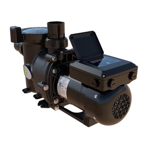
This manual contains information for the proper
installation, operation, and maintenance of the Zodiac
E3 variable speed pump. Procedures in this manual
must be followed exactly. To obtain additional copies
of this manual, contact Zodiac® Customer Service at
800.688.552. For address information, see the back
cover of this manual.
2.2 Description
The E3 is a variable-speed pump that can be run from
1900 RPM to 2840 RPM. The pump provides three
separate program modes to vary the speed settings that
are accessible by a simple touch of a button. This allows
for simple operations that can greatly reduce operating
costs at a reasonable investment.
WARNING
Pump suction is hazardous and can trap and
drown or disembowel bathers. Do not use or
operate swimming pools, spa, or hot tubs if a
suction outlet cover is missing, broken, or loose.
Thefollowingguidelinesprovideinformationforpump
installationthatminimizestheriskofinjurytousersof
poolsandspas.RefertoAustralianStandard1926.3
forfurtherinformation.
WARNING
Thepumpisnotintendedforusebyyoungchildren
orinfirmpersonsunlesstheyhavebeenadequately
supervisedbyaresponsiblepersontoensurethat
theycanusethepumpsafely.Youngchildrenshould
besupervisedtoensurethattheydonotplaywiththe
pump.
EcoMode:1900RPM
CleanMode:2150RPM
BoostMode:2840RPM
Section 3.
Installation
Information
3.1 Plumbing
3.1.1 Preparation Information
1. Upon receipt of the pump, check the carton for
damage. Open the carton and check the pump
for concealed damage, such as cracks, dents
or a bent base. If damage is found, contact the
shipper or distributor where the pump was
purchased.
2. Inspect the contents of the carton and verify
that all parts are included, see Section 7.1,
Replacement Parts List and Exploded View.
3.1.2 Pump Location
1. Zodiac Pool Systems, Inc. recommends
installing the pump within three hundred
millimetres (300mm) above water level. The
pump should not be elevated more than a metre
above the water level of the pool. A check
valve is recommended on the suction line of the
pump.
2. If the pump is located below water level,
isolation valves must be installed on both the
suction and return lines to prevent back ow
of pool water during any routine or required
servicing.
NOTE Whenthepoolequipmentislocatedbelowthepool
surfacealeakcanresultinlargescalewaterloss
orflooding.ZodiacPoolSystems,Inc.,cannotbe
responsibleforsuchwaterlossorfloodingordamage
causedbyeitheroccurrence.
3.1.3 Pipe Sizing
3.1.3.1 Discharge Pipe
When the pump is located up to 15 metres (15m) from
the pool, the recommended Class 9 minimum pipe size
for the discharge side of the pump is ninety millimetres
(90mm) for 0.75HP and fty millimetres (50mm) for
1-2 HP.
NOTE Allpipesizes(Class9)areabletowithstandthe
pressuresdeliveredbythepump,butnotnecessarily
theflow.Ifthepipeistoosmallforthepump,orif
thepumpiselevatedabovewater,themaximum
litresperminute(LPM)maynotbedelivered.If
thishappens,thepumpwilldevelopanairpocket
(cavitation)thatwillmakenoise,andthelifeofthe
pumpmaybeshortened.
Figure 1. E3 Pump Controls and Modes


