Zumax Medical OMS2360 User manual

Surgical Microscope
OMS2360/OMS2365
User’s Manual
The CE mark indicates that the product complies with the European medical device regulation
(EU) 2017/745.
Zumax Medical Co., Ltd.
5 Zhiying Street, Suzhou New District,
Suzhou, Jiangsu, China 215129
Phone:+86 512 66650502
Fax:+86 512 66909655
E-mail:Sales@zumaxmedical.com
Http://www.zumaxmedical.com
MedNet EC-REP GmbH
Borkstrasse 10, 48163 Münster, Germany

Precautions
Preface
Thank you for purchasing our OMS2360/OMS2365 Surgical Microscope. To prevent damage to your
product or injury to yourself or to others, read the following safety precautions in their entirety
before using this equipment. Keep these safety instructions where all those who use the product
will read them.
1. Do not use this instrument in an environment prone to fire or an environment with
dust/ airborne debris or with high temperatures. Use it in a clean and dry indoor
setting only.
2. Check that all the wires are correctly and firmly connected before using. Ensure
that the instrument is well grounded.
3. Please pay attention to all the rated electrical values of any connecting terminals.
4. Only use fuse/voltage outputs according to the specifications and rated values
stipulated by our product.
5. Use the power cable supplied with this instrument only;
6. Do not touch the surface of the lens and prism by bare hand or with solid objects
that may damage the surface.
7. Turn off the main power first before replacing the illumination bulb and fuse.
8. To prevent the instrument from falling or tipping over, the instrument should be
placed on a floor where the inclination angle is less than 10º.
9. Turn off the power and cover the instrument with dust-proof hood when it is not in
use.
10. In case there is any trouble, please first refer to the trouble-shooting guide. If it still
cannot be resolved, please contact the authorized distributor or our After-sales
Service Department.
* THE SAFETY MARKS USED IN THIS INSTRUMENT

Ground Terminal
Electrostatic
discharge warning
<12 Kg
Weight limit
Brightness adjustment
Video plug
Power plug
Balance arm
regulation
Caution
Operating
instructions
Warning

Contents
_____________________________________________________________________________________________
1. Purpose and Features ................................................................................................................................. 1
1.1 Purpose ................................................................................................................................................ 1
1.2 main structure composition ............................................................................................................ 1
1.3 Features ............................................................................................................................................... 1
1.4 performance....................................................................................................................................... 1
1.5 contraindications ............................................................................................................................... 1
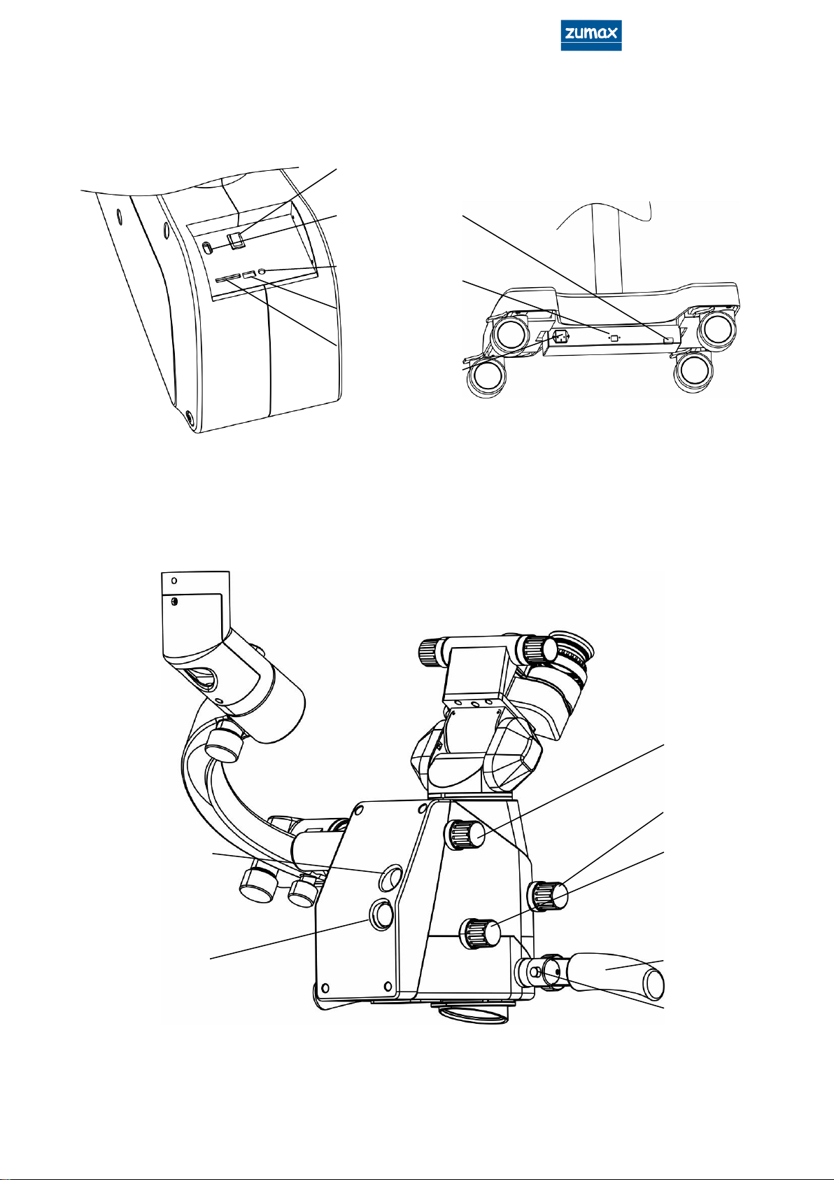
2. Main components .................................................................................................................................... 2-7
3. Assembly .................................................................................................................................................. 8-10
3.1 Assembly of base ............................................................................................................................... 9
3.2 Assembly of the first arm.................................................................................................................... 9
3.3 Assembly of microscope head ...................................................................................................... 10
3.4 Assembly of 190ºinclinable binocular........................................................................................... 10
3.5 Assembly of handle.......................................................................................................................... 10
3.6 Assembly of the LED power cable ................................................................................................. 10
3.7 How to connect the power cable................................................................................................. 10
3.8Built-in camera connection ............................................................................................................ 10
3.9Video output connection ............................................................................................................... 10
4. Use of the microscope ......................................................................................................................... 11-14
4.1 Necessary working condition ......................................................................................................... 11
4.2 Precautions........................................................................................................................................ 11
4.3 Installation and adjustment before Use ........................................................................................ 11
4.3.1 Adjusting the balance of second Arm................................................................................ 11
4.3.2 Adjusting the microscope..................................................................................................... 12
4.4 Inspection before Use...................................................................................................................... 12
4.5 Using the microscope ...................................................................................................................... 13
4.6 Movement and storage after Use.................................................................................................. 14
5. Maintenance ........................................................................................................................................ 15-16
5.1 Replacing the consumable parts .................................................................................................. 15
5.1.1 Replacing the LED.................................................................................................................. 15
5.1.2 Replacing the fuse................................................................................................................. 15
5.2 Cleaning and sterilization................................................................................................................ 15
5.2.1 Cleaning the surface of equipment ................................................................................... 15
5.2.2 Cleaning the surface of the optical lens ............................................................................ 15
5.2.3 Sterilization............................................................................................................................... 16
5.3 disposal of wastes ............................................................................................................................ 16
6. Microscope occessories list ................................................................................................................. 17-18
7. Trouble shooting Guide............................................................................................................................. 29
8. Technical specifications ......................................................................................................................20-22
9. EMC ........................................................................................................................................................ 23-25

1
1. Purpose and Features
1.1 Purpose
The surgical microscope OMS2360, OMS2365 (OMS2360, OMS2365) is applicable to the
microsurgery and fine examination of dental clinical subjects (except ophthalmology).
1.2 main structure composition
OMS2360, OMS2365 composed of the optical system, including the variable
magnification zoom lens, the binocular eyepiece, as well as the lighting system, stents,
electrical devices, can all be configured according to different application requirements
along with the corresponding accessories.
1.3 features
OMS2360, OMS2365 can enable teaching through built in photography and video capture
accessories.
OMS2360, OMS2365 use 190 °adjustable binoculars eyepieces that can be angled to match
the desired positioning for optimal operator viewing comfort.
A specially designed LED light source provides the maximum intensity of illumination needed
to work confidently.
OMS2360 for six times system, OMS2365 to five times.The eyepiece is wide Angle design, the
optical system image is clear, the field is big, the field is long.The built-in zoom lens provides a
larger range of work distance adjustment for doctors.
Built-in color filters with a yellow filter and green filter, Yellow for anti polymerization, green for
surgery.
Stepless brightness adjustment knobs conveniently located on the instrument allow for the
exact level of illumination required to be easily selected.
The cross arm is designed with a spring balance, so that the microscope stays at the right
operating height after positioning without moving up/down. While the microscope is in regular
use, the LED illumination will remain ON, and if the microscope is moved out of operating
range, the LED illumination will automatically turn off allowing for efficient storage when not in
use.
1.4 performance
After taking magnification into account, the viewing point of reference offset is not greater
than 10% of the diameter of the field.
The uniform illumination of the field of view has a color rendering index greater than 85%,
allowing for more accurate visualization of structures and media.
working noise of 65 dB (A) or less.
The large zoom objective lens working distance error is not more than 15%, for example the
shortest working distance is 200 +/- 30 mm, the longest working distance is 450 + / - 67.5 mm.
1.5 contraindications
No clear contraindications have been found.

2
2. Main components
Fig.1 general assembly view
1
3
4
2
6
7
8
9
13
A
5
11
14
10
12

3
Fig.3 Right back-side view
Fig.2-1 A direction view
23
24
25
26
28
29
Fig.2-2 base view
15
16
17
18
19
22
21
20
27

4
Fig.5 Assembly the camera
Fig.4 Left back-side view
32
31
36
34
37
35
38
33

5
Fig.6 accessories parts
39
41
40
42
44
43
45

6
[1] Star handler fixation screw.
Lock/unlock the second arm.
[2] Balance adjustment screw for second arm.
Rotate the screw with 8mm special driver to adjust the balance of the second arm.
[3] Star handler fixation screw.
Use this screw to adjust the vertical moving balance on the second arm.
[4] Star handler fixation screw.
Use this screw to adjust the damping of the connecting arm.
[5] Star handler fixation screw.
Use this screw to adjust the damping of the horizontal movement of the first arm.
[6] Lens around the balance lock knob.
[7] Lens balance balance knob.
[8] lens front and rear balance lock knob.
[9] The lens front and rear balance adjustment knob
[10] Fixation screw of main microscope..
Used to fix the main eyepiece tube.
[11] Foot Wheel.
Lock the brakes to fix the microscope in place.
[12] The second arm plate.
[13] 12.5X eyepiece
The eyepiece has a dioptric adjustment ring and a goggles height adjustment ring.
[14] Focus knob
Use this knob to manually adjust the focal length of the surgical microscope, focusing
range is 200 mm ~ 450 mm.
[15] Main Power Switch
To turn on or turn off the main power of the microscope.
[16] 110V/220V Voltage selector
Pushing the selector upwards converts voltage is 110V, pushing the selector downwards
converts input voltage is 220V.
[17] Debug jack
[18] USB jack
Insert USB flash drive to save photos or videos or USB receiver to use a wireless mouse for
taking pictures, video and making pics scrolling.
[19] SD card jack
Insert SD card to save photos or videos.
[20] HDMI video output jack
[21] Internet cable socket
[22] Main power socket, fuse socket.
Pull out the power table, right side is fuse socket, fuse specification: T1.25 A/H250 V for

7
220VAC; T2.5 A/H250 V for 110VAC.
[23] Fluorescent protection knob (optional)
Switch the LED switch knob to Fluorescent light source and turn the Fluorescent protection
knob then the fluorescent lamp will turn ON.
[24] magnification knob
The OMS2365 can be switched between 5 mag ratios: 0.4x, 0.6x, 1x, 1.6x, 2.5x, OMS2360
can be switched between 6 mag ratios: 0.3x, 0.5x, 0.8x, 1.2 X, 2x, 3x.
[25] Filter selection button.
Rotate this knob to select large and medium light spots and yellow filters, green filters and
no filters.
[26] handle
The operation microscope is operated on the top and bottom, front and back, left and
right, rotation and so on.
[27]Photo/Video button.
Kick button to take photo. Long kick button to record video, kick it again to exit video
recording.
[28] Built-in camera joint.
[29] LED power cable and the joint for power cable.
[31] Balance arm
[32] Illumination brightness adjusting button.
Rotate this button to adjust the brightness of the illumination. A contact switch installed in
the second arm serves to switch off the bulb when the microscope is in "parking" position.
[33] Photo/Video button.(Same [27])
[34] Camera (optional)
For taking photos while microscope is in use.
[35] Digital camera adapter (optional)
Used to connect the corresponding digital camera.
[36] External camera (optional)
[37] External camera adapter (optional)
[38] Beam splitter (optional)
[39] Binocular extender (optional)
[40] Rotating ring (optional)
[41] Binocular extender and splitter(optional)
[42] Dual iris diaphragm (optional)
[43] 190 °inclinable binocular
[44] Straight binocular
[45] 45 °skimmer binocular

8
3. Assembly
The microscope is packed in one package. Please open the package and take out all parts
and assemble them according to the following procedures.
Fig.7 Assembly drawing of microscope
connecting arm
The first arm
column
Base
Support arm
binocular
The second arm

9
3.1 Assembly of base
(1) Please take out the base support from the package, lay it on the ground.
(2)Take out the pole, place the pole on the base, and after fixing the cable then secure the 4
screws.
(3) Place the plastic cover on the metal base
3.2 Assembly of the first arm
Take out the first arm,please pay attention, the star handler fixation screw [3] must be
tightened in advance, insert the hole to the axis, then use jump ring pliers to fix the two
axis with jump ring in the circle groove, put on the cover.
ATTENTION: the second arm uses a balancing spring. The knob [3] can only be
tightened but not locked, therefore it is advisable to loosen the screw with the Allen
key that is under the cap of the knob itself only with the arm inserted on the pole
and the head mounted.
Fig.8 Assembly of base

10
3.4 Assembly of microscope head
Take out microscope head from the packing, tighten with M4 socket hexagon screw.
3.5 Assembly of 190ºinclinable binocular
Take out the 190ºinclinable binocular from the package, fix it to the microscope head ,
make sure the pin is in the right position, then tighten the screw [10]。
3.6 Assembly of handle
Manipulating handle [26] is fixed on the lower part of microscope, Handle angle can be
adjusted as you needed.
3.7 Assembly of the LED power cable
The LED power cable is fixed on the first and second arm. Plug LED power cable into the
joint [28].
3.8 How to connect the power cable
Take out the power cable and plug it into the power socket [22]on the base of the
microscope.
3.9 built-in camera connection
Insert the built-in camera cable on the connector [29].
3.10 video output connection
The video output cable is plugged into HDMI interface [20] on the base of the
microscope and the other end is connected to the monitor connector.
Caution:The terminals of LED power cable must be plugged in the right holes of the
joint.
Fig.8 Assembly of microscope head
M4

11
4. Use of the microscope
4.1 Necessary working condition
Please make check the following points, and continue thereafter:
● Please check whether the main voltage and frequency complies with what required
by this equipment. If you will operate the equipment at 110V, please switch the
selecting switch [16] to the 110V setting and change the fuse to type T2.5 A/H250 V as
supplied。If you will operate the equipment at 220V, please switch the selecting switch
[23] to the 220V setting and change the fuse to type T1.25 A/H250 V as supplied。
● Check the grounding of power supply. Make sure the equipment has a good
ground-wire connection.
● Please use the power cable supplied with this equipment.
● Please make sure that all mechanical parts important for your safety are assembled
correctly.
4.2 Precautions
● Please never watch the light source directly through the objective.
●The terminals of LED power cable must be plugged into the right holes of the joint.
● Please do not cover the heat elimination grooves of power source。
● Please pay special attention to the caution signs on the equipment.
4.3 Installation and Adjustment before use
4.3.1Adjusting the balance of second arm
● Hold the second arm, unscrew the star handle fixation screw [3].
● Insert a 8 mm inner hexagon spanner into the screw [2].
●Make sure the second arm remains in a horizontal position
● Rotate the screw [2] to adjust the balance of second arm.
● Adjust the second arm, check the balance of second arm in multiple positions.
● Adjust the star handle fixation screw [3] until the upwards and downwards resistance
Warning: To avoid the risk of electric shock, this equipment must only be
connected to a grounded power supply.
Warning: To avoid the risk of mechanical hazards, this equipment must
only be used in a controlled indoor environment.
Warning: Exposure to eyes limit tmax =90 seconds.
Warning: If using Fluorescent, make sure the laser protection module is on[23].

12
are almost equivalent.
● When adding or removing accessories, readjustment of the balance of the second
arm is necessary.
4.3.2 Adjusting the microscope
● Carry out this adjustment in your normal working position, switch to 0.3 x magnification,
adjust the working distance and pupil distance of the microscope.
● Emmetropes/ operators who do not need corrective glasses:adjust the eyepiece to 0.
● Operators using his/her corrective glasses: adjust the eyepiece to 0.
● Ametropes/ operators who need corrective glasses who know their refractive powers
and perform surgery without wearing their glasses:adjust the eyepiece to his/her own
eyesight.
● Ametropes/ operators who need corrective glasses, who do not know their refractive
powers and perform surgery without wearing their glasses, use the following
procedure:Adjust both eyepieces to +5D,take the eyepiece and eyepiece tube from
the microscope, observe a distant object through the eyepiece, just like using a
telescope. Then rotate the diopter adjustment hoop until the image is clear. If
necessary, repeat this process for three times. Use the same method to adjust the
second eyepiece. Assemble the eyepiece and eyepiece tube back to microscope
body, tighten the fixation screw [10].
● Adjust the eye-cover until the whole visual field can be observed. Adjust the
magnification to 3x , when you feel the image is clear, return to the magnification you
want. The image is still clear when you change the magnification, but different in
depth of field for each magnification.
4.4 Inspection before use
Please inspect the following points before the operation:
-Check if all fixation screws and lock pins have been tightened.
-Turn on the power switch, then check the following items:
Illumination:
● LED should be in good condition.
● When moving the second arm up and down, the LED light must switch on and off. The
LED turns off automatically when the microscope is in "parking" position.
● The LED power cable has been connected.
Set balance:
●Ground must be level, so the column will be level.
● The damping of first arm, second arm, connecting arm (optional accessories) and the
Caution:The second arm must be held firmly before unscrewing the star handle
fixation screw [3].
Caution: It is necessary to make a form if several doctors share an operation
microscope. Every doctor’s diopter should noted. Keep the form where all those
doctors who use the microscope can find it.

13
microscope has already been adjusted.
Microscope:
Adjusting the magnification:
●Magnifying knob is [24] working correctly.
Eyepiece:
● The screw [10] to fix the eyepieces has been tightened.
● Operating microscope and eyepieces have been adjusted in a suitable position for
the operation.
● Pupil distance has been adjusted.
● The eye-cover height has been adjusted to assure the whole visual field can be
observed.
● The diopter has been adjusted.
● The images are clear in each magnification setting.
Filter selector:
●Filter selector [25] is in good condition.
Base:
● The foot wheels brakes have been set.
Disinfection cover and handles:
● Star handle fixation screws, magnifying knob, illumination brightness adjusting button、
pupil distance adjustment knob, fine focusing adjustment knob etc. have been
equipped the sterile covers.
● Microscope head may be equipped with a single use sterile cover according to
doctor’s requirement.
4.5 Using the microscope
-Please make sure the above steps had been taken care of.
-The equipment had been inspected according to the requests of Inspection Form.
● Turn on the power switch.
● Move the second arm up and down to the right working position.
● Adjust the illumination.
● Select the filter which will be used.
● Move the microscope lens into the operation area, then adjust it to a suitable position.
● Adjust the magnification.
● Move the operation microscope, adjust rough focusing through the eyepieces, then
adjust fine focus.
● Move the second arm to working scope, set a available angle, then lock it by Star
handler fixation screw[3].
● if the equipment is not in use, main power should be off.
Caution:Make sure the heat elimination groove are not covered.
Caution:When foot wheels are fixed, Pushing horizontal prohibited

14
4.6 Movement and Storage after use
● Put off all rubber caps and handles which can be sterilized in autoclaves. We
● Fold the microscope back near the column. Fasten every star knob firmly to fix the arm
and the microscope.
● Release the brakes of the wheels.
● While moving the equipment, hold the movement handles and make the equipment
move slowly and carefully to avoid falling and bumping.
● When the storage place has been reached, lock the brakes of the wheels.
● Put on the dust cover.

15
5. Maintenance
5.1 Replacing the consumable parts
5.1.1Replacing the LED
Please contact the after-sales service department.
5.1.2 Replacing the fuse
The fuse is integrated with main power input socket.
Please replace the fuse according to the following steps:
● Turn off the main power switch.
● Pull out the power plug from the main power plug [22].
● Find the fuse socket on the right side of power plug [22], take out the fuse socket from
the side with a small screwdriver.
● Take out the melted fuse.
● Insert a new fuse and insert the fuse socket back again.
● Plug in power cable.
● Turn on the main power switch.
Specification of fuse:T1.25 A/H250 V for 220VAC
T2.5 A/H250 V for 110VAC
5.1.3 Replacing the power supply cords
Replacement the power supply cords should by the manufacturer specifies service
person.
5.2 Cleaning and Sterilization
5.2.1 Cleaning the surface of equipment
The outer surface of the equipment may be cleaned with a wet cloth. The remaining
stains can be cleaned off with a mixture of 50% C2H5OH and 50% distilled water. Do not
use any corrosive detergent or the surface may be damaged.
5.2.2 Cleaning the surface of the optical lens
To prevent the dust from staining the lens, never expose the optical lens to air without
the objective, eyepiece tube and eyepiece. Please use the dust cover after using the
microscope.
Cleaning the surface of the optical lens: To clean the dirt on lens, such like bloodstain,
Caution:Please use the bulb specially designed for this equipment.
Caution: Dirt on the lens must be cleaned immediately after the surgery. It will be
hard to clean when the dirt air-dried.
Warning: To avoid the unacceptable risk, please use the special cords for
the equipment.

16
please use a special paper or absorbent cotton with a little bit of distilled water and wash
off, the remaining stains can be cleaned off with a mixture of 50% ethanol and 50% ether.
If there is dust on the lens, blow the dust off with a dust pen. Do not wipe the lens with any
corrosive detergent, otherwise it may be damaged.
5.2.3 Sterilization
All sterilization caps should be sterilized by autoclave. The following temperature and
time are recommended:
Sterilization temperature: 134℃for 10 minutes;
5.3 disposal of wastes
The waste produced by this instrument is LED light source, mirror paper or nonfat
cotton. Please do not discard it. If there is a special waste treatment facility nearby,
please use it as far as possible.The discarded instruments are processed according to the
local environmental protection law. Please do not pollute the environment.
This manual suits for next models
1
Table of contents
Other Zumax Medical Microscope manuals