Zumax Medical OMS2350 User manual

Issue date:2020/3/16
-1-
Surgical Microscope
OMS2350
User Manual
The CE mark indicates that the product complies with the European medical
device regulation (EU) 2017/745.
Zumax Medical Co., Ltd.
5 Zhiying Street, Suzhou New District, Suzhou, Jiangsu, China 215129
Phone:+86 512 66650502
Fax:+86 512 66909655
http://www.zumaxmedical.com
E-mail:sales@zumaxmedical.com
MedNet EC-REP GmbH
Borkstrasse 10, 48163 Münster, Germany

Issue date:2020/3/16
-2-
Precautions
Preface
Thank you for purchasing our Surgical Microscope. To prevent damage to your product
or injury to you or to others, read the following safety precaution in their entirety before
using this equipment. Keep these safety instructions where all those who use the product
will read them.
1. Do not use this instrument in the environment prone to fire and blast or
where there is much dust and with high temperature. Use it in the room
and simultaneously be careful to keep it clean and dry;
2. Check that all the wires are correctly and firmly connected before using.
Ensure that the instrument is well grounded.
3. Please pay attention to all the rated values of the electrical connecting
terminal.
4. Only use fuse according to the specifications and rated values
stipulated by our product.
5. Use the power cable supplied with this instrument only;
6. Do not touch the surface of the lens and prism with hand or hard
objects.
7. Turn off the main power first before replacing the illumination bulb and
fuse.
8. To prevent the instrument from falling down to floor, it should be placed
on the floor where the inclination angle is less than 10º.
9. Turn off the power and cover the instrument with dust-proof hood when
it is not in use.
10. In case there is any trouble, please first refer to the trouble-shooting
guide. If it still cannot work, please contact the authorized distributor or
our After-sales Service Department.

Issue date:2020/3/16
-3-
* THE MARKS USED IN THIS INSTRUMENT
The black dot is the video interface The blue dot is the LED power interface
Operating
instruction
s
Warning
Caution
Protective earth
(ground).
light-dimmer
Increase the brightness clockwise
Reduce the brightness counterclockwise
ESD
Balance adjustment

Issue date:2020/3/16
-1-
Contents
1. Purpose and Features.................................................................................................................1
1.1 Purpose................................................................................................................................1
1.2 Features...............................................................................................................................1
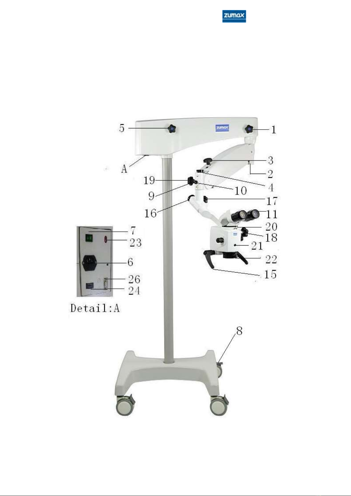
2. Main components........................................................................................................................2
3. Assembly ......................................................................................................................................7
3.1 Assembly of base ................................................................................................................8
3.2 Assembly of the first arm....................................................................................................8
3.3 Assembly of 120 deg coupling............................................................................................9
3.4 Assembly of microscope head.............................................................................................9
3.5 Assembly of 180ºinclinable binocular tube........................................................................9
3.6 Assembly of handle...........................................................................................................10
3.7 Assembly of the LED power cable ...................................................................................10
3.8 How to connect the power cable.......................................................................................10
4. Use of the microscope ...............................................................................................................11
4.1 Working conditions...........................................................................................................11
4.2 Installation and Adjustment before use.............................................................................12
4.2.1Adjusting the balance of second arm......................................................................12
4.2.2 Adjusting the microscope.......................................................................................12
4.3 Inspection before use ........................................................................................................13
4.4 Using the microscope........................................................................................................14
4.5 Movement and Storage after use.......................................................................................14
5. Maintenance ..............................................................................................................................16
5.1Replacing the consumable parts.........................................................................................16
5.1.1Replacing the LED..................................................................................................16
5.1.2 Replacing the fuse..................................................................................................16
5.1.3 Replacing the power supply cords .........................................................................16
5.2 Cleaning and Sterilization.................................................................................................16
5.2.1 Cleaning the surface of equipment.........................................................................17
5.2.2 Cleaning the surface of the optical lens .................................................................17
5.2.3 Cleaning and disinfection of sterilizable caps........................................................17
5.2.4 Sterilization of sterilizable caps .............................................................................17
6. Microscope accessories list.......................................................................................................18
7. Trouble-shooting guide.............................................................................................................21
8. Technical specification..............................................................................................................22
9. EMC (electromagnetic compatibility).....................................................................................23

Issue date:2020/3/16
-1-
1. Purpose and Features
1.1 Purpose
The microscope OMS2350 is used for ENT surgery, dental surgery, neurosurgery,
dermatology or other surgery except ophthalmology.
1.2 Features
OMS2350 is based on a hanging arm design, it helps the operator by
automatically adjusting the exposure, fatigue is minimized even after prolonged
use.
Six–step magnification for the main microscope, the optical system assures a
perfectly clear images.
Cool illumination by LED lamp. Natural colors.
Hanging arm design, so the arm can be moved randomly. A special switch has
been fitted into the Second Arm: The lamp will keep “on” when the arm is
working in its normal range, in "parking" position, the lamp will turn off
automatically.
Fig.1 Microscope head

Issue date:2020/3/16
-2-
2. Main components
Fig.2 General assembly of microscope

Issue date:2020/3/16
-3-
Fig.3 Back-side view
27
Fig.4 Integrated full HD camera
28
25
12
13
14

Issue date:2020/3/16
-4-
[1] Star handler fixation screw.
Hang the microscope on the second arm using this nut.
[2] Balance adjustment screw for second arm.
Rotate the screw with 8mm special spanner to adjust the balance of the
second arm.
[3] Star handler fixation screw.
Use this screw to adjust the vertical moving balance on the second arm.
[4] Fixation nut.
Hang the microscope on the second arm using this nut.
[5] Star handler fixation screw.
Use this screw to adjust the damping of the horizontal movement of the first
arm.
[6] Main power socket, fuse socket.
Pull out the power table, right side is fuse socket, fuse specification: T1.25
A/H250 V for 220VAC; T2.5 A/H250 V for 110VAC.
[7] Main Power Switch.
To turn on or turn off the m1ain power of the microscope.
[8] Foot Wheel.
Lock the brakes to fix the microscope in place.
[9] Star handler fixation screw.
Use this screw to adjust the damping of the120ºconnecting arm.
[10] Illumination brightness adjusting button.
Rotate this button to adjust the brightness of the illumination. A contact
Fig.5 Interface details

Issue date:2020/3/16
-5-
switch installed in the second arm serves to switch off the bulb when the
microscope is in "parking" position.
[11] Binocular tube
[12] LED power cable and the joint for power cable.
[13] Column
[14] Filter selection button.
Rotate this button to select the filters. There are positions: No filter/ Green
filter/ Yellow filter
[15] Manipulating handle.
For rough focusing, move the microscope up and down or right and left.
Available in Type ‘8’. (BFR: I don`t understand, this needs a bit of
explanation or leave the text away)
[16] Fixation nut.
Hang the microscope on the 120ºcoupling using this nut.
[17] Star handler fixation screw.
Use this handle to adjust the damping of the microscope’s hanging axis.
[18] Star handler fixation screw.
Use this handle to adjust the damping of the microscope’s pitch.
[19] Locking pin.
Keep the microscope from falling when assembling and disassembling
accessories.
[20] Fixation screw of main microscope.
Used to fix the main eyepiece tube.
[21] Manipulating handle position.
Available in Type ‘T’.
[22] Fine focusing adjustment knob.
Rotate this knob to adjust the focus of the objective, focusing distance:
11mm.
[23] 110V/220V Voltage selector.
Pushing the selector upwards, input voltage is 110V, pushing the selector
downwards, input voltage is 220V.
[24] The joint for monitor (Optional)
It can output video of built-in camera.
[25] video interface (Optional)

Issue date:2020/3/16
-6-
[26] HDMI debug interface (Optional)
[27] Integrated full HD camera with SD card (Optional)
Microscope head has two buttons as shown in the figure3. Press the left
button will take a picture; press the right button will record video.
Interface details on the arm as shown in the figure4.
[28] Interface details on the arm(LAN、HDMI、SD Card、USB、Debug) (Optional)
[29] Inner Camera Remote Control Kit (Optional)
The details see instruction of inner camera remote control kit.

Issue date:2020/3/16
-7-
3. Assembly
The microscope is packed in one package. Please open the package and take out all
parts and assemble them according to the following procedures.
Fig 6. Assembly drawing of microscope

Issue date:2020/3/16
-8-
3.1 Assembly of base
(1) Please take out the base support from the package, lay it on the ground.
(2) Take out the pole, turn out the inner hexagonal screw and gasket. Insert the pole
into the hole of the floor stand, make sure that the pin of the floor stand installed in
the hole of the pole. Assemble everything in the following order: gasket, spring gasket,
socket screw. Finally fasten the socket screw firmly with an 8mm allen key.
Fig 7. Assembly of base
3.2 Assembly of the first arm
Take out the first arm,please pay attention, the star handler fixation screw [3] must be
tightened in advance, insert the hole to the axis, then use jump ring pliers to fix the
two axis with jump ring in the circle groove, put on the cover.
Caution:The Second Arm use a spring to keep the balance. The
star handler fixation screw [3] can only to tighten the
arm, the arm can not be locked by this screw. The
second Arm must be held before loosening the star
handler fixation screw [3].

Issue date:2020/3/16
-9-
3.3 Assembly of 120 deg coupling
(1) Rotate the star handler fixation screw [9] a little bit until the screw tip does not
above the shaft hole; Rotate the Locking pin [19] a little bit until the tip does not
above the shaft hole.
(2) Take out the Fixation nut [4] from 120ºcoupling, apply a little bit engine oil or
grease on its axis, insert the axis into the hole of second arm from the bottom to up,
tighten the locking pin [19] make the locking pin [19] into the axis groove, tighten the
fixation nut [4] finally.
Fig 8 Assembly drawing of 120ºcoupling
3.4 Assembly of microscope head
Take out the microscope head connect it with the hanging axis. Use the method as
same as 3.3 to assemble the microscope head to the 120ºcoupling.
3.5 Assembly of 180ºinclinable binocular tube
Take out the 180ºinclinable binocular from the package, fix it to the microscope head
make sure the pin is in the right position, then tighten the screw [21].

Issue date:2020/3/16
-10-
3.6 Assembly of handle
Manipulating handle [15] is fixed on the lower part of microscope, T type handle [21]
is fixed on the front of microscope. Assemble the manipulating handle [15] or T type
handle supplied with your equipment, then tighten the screw.
According your needs, select manipulating or T type handle.
3.7 Assembly of the LED power cable
The LED power cable is fixed on the first and second arm. Plug LED power cable into
the joint [12].
Caution:The terminals of LED power cable must be plugged in
the right holes of the joint.
3.8 How to connect the power cable
Take out the power cable and plug it into the power socket [6].

Issue date:2020/3/16
-11-
4. Use of the microscope
Warning: To avoid the risk of electric shock, this equipment must
only be connected to a supply mains with protective
earth.
Warning: To avoid the risk of mechanical hazards, this equipment
must only be used in room without threshold.
Warning: Exposure to eyes limit tmax =90 seconds.
4.1 Working conditions
Please make check the following points, and continue thereafter:
● Please check whether the main voltage and frequency complies with what required
by this equipment. If you will operate the equipment at 110V, please switch the
selecting switch [23] to the 110V block and change the fuse to type T2.5 A/H250
V as supplied. If you will operate the equipment at 220V, please switch the
selecting switch [23] to the 220V block and change the fuse to type T1.25
A/H250 V as supplied.
● Check the grounding of power supply. Make sure the equipment has a good
ground-wire connection.
● Please use the power cable supplied with this equipment.
● Please make sure that all mechanical parts important for your security are assembled
correctly.
cautions:
● Please never watch the light source directly through the
objective.
●The terminals of LED power cable must be plugged in the
right holes of the joint.
● Please do not cover the heat elimination grooves of power
source.
● Please pay special attention to the caution signs on the
equipment.

Issue date:2020/3/16
-12-
4.2 Installation and Adjustment before use
4.2.1Adjusting the balance of second arm
● Hold the second arm, unscrew the star handle fixation screw [3].
● Insert an 8 mm inner hexagon spanner into the screw [2].
● Rotate the screw [2] to adjust the balance of second arm.
● Adjust the second arm, check the balance of second arm in multiple positions.
● Adjust the star handle fixation screw [3] until the upwards and downwards
resistance are almost equivalent.
● When adding or removing accessories, readjustment of the balance of the second
arm is necessary.
Caution:The second arm must be held firmly before unscrewing
the star handle fixation screw [3].
4.2.2 Adjusting the microscope
● Carry out this adjustment in your normal working position, switch to 0.3 x
magnification,adjust the working distance and pupil distance of the microscope.
● Emmetropes/ operators who do not need corrective glasses:adjust the eyepiece to 0.
● Operators using his/her corrective glasses: adjust the eyepiece to 0.
● Ametropes/ operators who need corrective glasses who know their refractive powers
and perform surgery without wearing their glasses:adjust the eyepiece to his/her
own eyesight.
● Ametropes/ operators who need corrective glasses, who do not know their refractive
powers and perform surgery without wearing their glasses, use the following
procedure:Adjust both eyepieces to +5D,take the eyepiece and eyepiece tube
from the microscope, observe a distant object through the eyepiece, just like
using a telescope. Then rotate the diopter adjustment hoop until the image is
clear. If necessary, repeat this process for three times. Use the same method to
adjust the second eyepiece. Assemble the eyepiece and eyepiece tube back to
microscope head, tighten the fixation screw [20].
● Adjust the eye-cover until the whole visual field can be observed. Adjust the
magnification to 3x, when you feel image clear, return to the magnification you
want. The image is still clear when you change the magnification, but different in

Issue date:2020/3/16
-13-
depth of field for each magnification.
Caution: It is necessary to make a form if several doctors
share an operation microscope. Every doctor’s
diopter should have noted. Keep the form where
all those doctors who use the microscope find it.
4.3 Inspection before use
Please inspect the following points before the operation:
-Check if all fixation screws and lock pins have been tightened.
-Turn on the power switch, then check the following items:
Illumination:
● LED should be in good condition.
● When moving the second arm up and down, the LED light must switch on and off.
The LED turns off automatically when the microscope is in "parking" position.
● The LED power cable has been connected.
Set balance:
●Ground must be level, so the column will be level.
● The damping of first arm, second arm, 120ºconnecting arm (optional accessories)
and the microscope has already been adjusted.
Microscope:
Adjusting the magnification:
●Magnifying knob is [13] working correctly.
Eyepiece:
● The screw [11] to fix the eyepieces has been tightened.
● Operating microscope and eyepieces have been adjusted in a suitable position for
the operation.
● Pupil distance has been adjusted.
● The eye-cover height has been adjusted to assure the whole visual field can be
observed.
● The diopter has been adjusted.
● The images are clear in each magnification setting.
Filter selector:

Issue date:2020/3/16
-14-
●Filter selector [14] is in good condition.
Base:
● The foot wheels’ brakes have been set.
Disinfection cover and handles:
● Star handle fixation screws, magnifying knob, illumination brightness adjusting
button、pupil distance adjustment knob, fine focusing adjustment knob etc. have
been equipped the sterile covers.
● Microscope head may be equipped with a single use sterile cover according to
doctor’s requirement.
Caution:When foot wheels are fixed, pushing horizontal prohibited
4.4 Using the microscope
-Please make sure the above steps had been taken care of.
-The equipment had been inspected according to the requests of Inspection Form.
● Turn on the power switch.
● Move the second arm up and down to the right working position.
● Adjust the illumination.
● Select the filter which will be used.
● Move the microscope lens into the operation area, then adjust it to a suitable
position.
● Adjust the magnification.
● Move the operation microscope, adjust rough focusing through the eyepieces, then
adjust fine focus.
● Move the second arm to working scope, set an available angle, then lock it by Star
handler fixation screw [3].
● if the equipment is not in use, main power should be off.
Caution:Make sure the heat elimination groove is not covered.
4.5 Movement and Storage after use
● Put off all sterilizable caps and handles which can be sterilized in autoclaves.
● Fold the microscope back near the column. Fasten every star knob firmly to fix the
arm and the microscope.

Issue date:2020/3/16
-15-
● Release the brakes of the wheels.
● While moving the equipment, hold the movement handles and make the equipment
move slowly and carefully to avoid falling and bumping.
● When the storage place has been reached, lock the brakes of the wheels.
● Put on the dust cover.

Issue date:2020/3/16
-16-
5. Maintenance
5.1Replacing the consumable parts
5.1.1Replacing the LED
Please contact the after-sales service department.
5.1.2 Replacing the fuse
The fuse is integrated with main power input socket.
Please replace the fuse according to the following steps:
● Turn off the main power switch.
● Pull out the power plug from the main power plug [6].
● Find the fuse socket on the right side of power plug [6], take out the fuse socket
from the side with a small screwdriver.
● Take out the melted fuse.
● Insert a new fuse and insert the fuse socket back again.
● Plug in power cable.
● Turn on the main power switch.
Specification of fuse:T1.25 A/H250 V for 220VAC
T2.5 A/H250 V for 110VAC
Caution:Please use the bulb specially designed for this equipment.
5.1.3 Replacing the power supply cords
Replacement the power supply cords should by the manufacturer specifies service
person.
Warning: To avoid the unacceptable risk, please use the
special cords for the equipment.
5.2 Cleaning and Sterilization
Caution: Dirt on the lens must be cleaned immediately after
the surgery. It will be hard to clean when the dirt
air-dried.
Table of contents
Other Zumax Medical Microscope manuals