Zummo MF14 User manual

011210/04

Español Pag. 03 / 10
English Pag. 11 / 18

3
ZUMMO-INNOVACIONES MECÁNICAS, S.A. en su constante afán por mejorar sus productos,
se reserva el derecho de modificar las máquinas sin previo aviso; por este motivo el presente
libro de instrucciones puede omitir los últimos cambios efectuados.
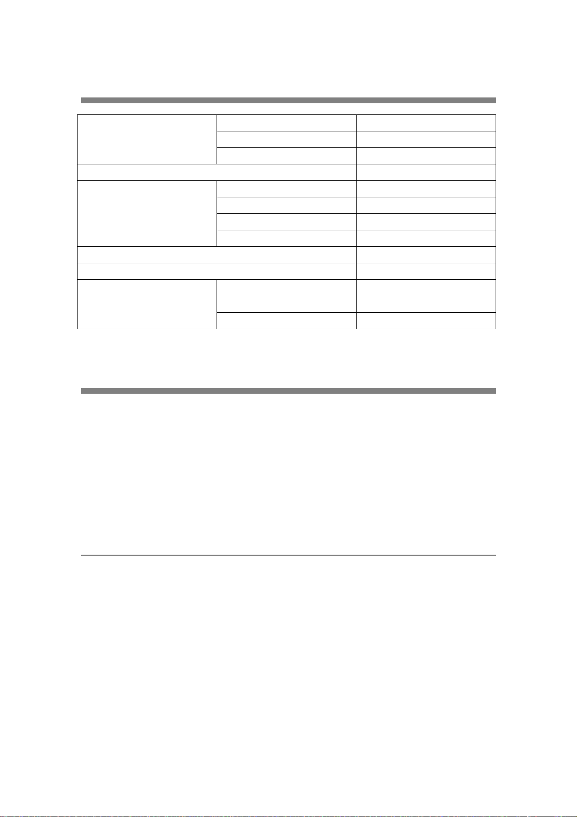
INDICE
Pág.
1 INSTRUCCIONES IMPORTANTES DE SEGURIDAD ......................................................... 3
2 INSTALACIÓN ...................................................................................................................3-4
3 FUNCIONAMIENTO .............................................................................................................. 4
4 CONTROL DE TEMPERATURA ......................................................................................... 4
5 MANTENIMIENTO .............................................................................................................4-5
6 LIMPIEZA ..........................................................................................................................5-6
7 ANOMALÍAS Y CAUSAS ..................................................................................................... 6
8 ESQUEMA ELÉCTRICO ....................................................................................................... 7
9 LISTADO DE PIEZAS ........................................................................................................7-8
10 RESIDUOS Y RECICLABILIDAD.......................................................................................... 8
11 DATOS TÉCNICOS................................................................................................................ 9
12 GARANTÍA ......................................................................................................................9-10
13 FOTOS.................................................................................................................................. 19
14 DESPIECES ....................................................................................................................20-22
1INSTRUCCIONES IMPORTANTES DE SEGURIDAD
•El fabricante no se hará cargo de las manipulaciones indebidas en el aparato.
•El fabricante declina toda responsabilidad en el caso de que no se sigan todas las
recomendaciones de este manual.
•Antes de realizar cualquier operación de limpieza o mantenimiento, hay que asegurarse de
que se haya desenchufado el mueble de la toma de corriente.
•No lavar el mueble con chorros de agua.
•Aparato no apto para uso exterior.
•Aparato no apto en instalaciones donde haya fuentes de agua cercanas.
•En caso de avería o mal funcionamiento, desenchufar el mueble y ponerse en contacto con
el servicio técnico.
•Para evitar riesgos toda reparación debe hacerse por personal técnico.
•El fabricante se reserva el derecho de realizar las modificaciones oportunas sin previo
aviso.
•Solicite el servicio de asistencia técnica a la empresa que le suministró la máquina; en caso
de no localizarla, contacte con el fabricante (datos en la portada de este manual).
2INSTALACIÓN
•Tras desembalar, controlar que el mueble no haya sufrido daños durante el transporte. De
haberlos sufrido, reclamar inmediatamente al transportista.
•En caso de duda, no utilizar el mueble y ponerse en contacto con su proveedor.
•No dejar al alcance de los niños bolsas de plástico, poliestireno, etc. ya que pueden ser
una fuente de peligro.
•En caso de que el mueble haya sido transportado acostado, debe mantenerse en posición
vertical una hora antes de su conexión, con el fin de que el aceite del compresor vuelva a
su lugar de origen y no resulte dañado el mismo.
•Colocar el mueble en el lugar deseado. Dejar un espacio libre de por lo menos 15cm
alrededor del mueble para no impedir el flujo de aire de refrigeración.
•Nivelar y estabilizar el mueble, mediante sus soportes.
•Atornillar la máquina al mueble con los tornillos suministrados. (Fig. 1)

4
•Antes de conectar el mueble a la red, consultar en la placa de matrícula (situada en el
lateral) que el voltaje es el adecuado (Fig. 2). Utilice una base de enchufe provista de una
eficaz toma de tierra y protegida por un diferencial de 0.03A conforme a las normas
vigentes. En el caso de que el enchufe no posea toma de tierra, consulte con un
especialista en electricidad. La toma de tierra es necesaria y obligatoria según la ley.
Cerciorarse que el aparato esté correctamente conectado a tierra; en caso contrario es
posible causar shocks eléctricos a las personas o dañar el equipo.
•Una vez comprobado lo anterior, proceda a conectar el mueble a la red.
•Conectar el enchufe directamente a la toma de corriente y evitar tomas múltiples.
•Se recomienda que antes de poner en funcionamiento el mueble, se efectúe una limpieza
de las piezas que van a estar en contacto con el zumo (contenedor, turbina, grifo, etc.)
•Monte el contenedor y el grifo, según se indica en la sección MONTAJE, del apartado
LIMPIEZA.
•Antes de activar el interruptor de la máquina consultar el apartado “Funcionamiento” y una
vez consultado poner la máquina en marcha. No conectar hasta tener una cantidad mínima
de zumo en el depósito (1cm por encima de la tapa para bomba). En caso contrario, la
turbina producirá espuma en exceso.
•Para la buena conservación del zumo es aconsejable tener el mueble refrigerador
permanentemente en funcionamiento.
3FUNCIONAMIENTO
•El mueble dispone de un único interruptor general que está situado en la parte trasera. (Fig.
3)
•Al conectar el interruptor se pone en marcha la turbina que agita el zumo. El sistema de
frío se pondrá en funcionamiento o se parará en función de la temperatura del zumo.
•El mueble va equipado con un dispositivo que permite accionar la máquina exprimidora
Z14 cada vez que se abre el grifo para llenar un vaso. Esto consiste en un cable con un
conector situado en la parte trasera del mueble que se deberá conectar a una máquina Z14
que esté previamente preparada con un conector para este fin. Cuando se abra el grifo del
mueble, la máquina exprimirá las naranjas que estén programadas en el selector.
•El mueble está preparado para funcionar con una temperatura ambiente comprendida entre
5° y 43° C.
4CONTROL DE TEMPERATURA
•Este mueble está diseñado para su utilización en autoservicios, por este motivo para evitar
que sea manipulado por personal ajeno a su mantenimiento el termostato se encuentra
oculto dentro del compartimiento del compresor.
•El termostato sale regulado de fábrica de forma que la temperatura del zumo oscile entre 4
y 7° C. (La posición del termostato está bloqueada para garantizar el correcto
funcionamiento del equipo, se recomienda no alterar su posición).
5MANTENIMIENTO
•Cada seis meses se aconseja eliminar la suciedad que se acumula en el condensador,
situado en el interior del mueble.

5
Para efectuar esta operación hay que quitar la rejilla que está en el lateral derecho. (Fig.
4). Evitar el contacto directo con las aletas del condesador porque tienen filo. Utilizar un
pincel o cepillo para limpiarlo.
•El eje de la turbina debe estar siempre engrasado. De fábrica sale engrasado con vaselina
autorizada para alimentación y se suministra un tubo de dicho producto como muestra.
(Fig. 5)
6LIMPIEZA
La limpieza es la parte más importante para garantizar la conservación y sabor del zumo
almacenado en el depósito. Limpiar diariamente el enfriador.
Para realizar esta operación, se aconseja seguir los siguientes pasos:
Apagar el interruptor y desconectar el aparato de la red.
Antes de desmontar para el lavado, debe vaciar completamente el zumo que pueda
quedar en el contenedor.
DESMONTAJE
•Retirar la tapa del contenedor ref. 0700003-1M. (Fig. 6)
•Retirar la placa de enganche ref. 0700003-2. (Fig. 6)
•Sacar la tapa de la bomba ref. 0700003-7. (Fig. 6)
•Quitar el contenedor vacío levantándolo por la parte posterior (opuesta al grifo) y
desprendiéndolo de la junta refs. 0700003-10 y 8. (Fig. 7)
•Quitar la junta del contenedor refs. 0700003-8. (Fig. 8)
•Sacar la turbina ref. 0700003-11. (Fig. 8)
•Sacar el pistón del grifo ref 0700003-14 tirando hacia arriba y desmontar la palanca
de mando ref. 0700003-13 desplazándola hacia la derecha. (Fig. 9)
LAVADO DEL MUEBLE
•Poner en un recipiente aproximadamente ocho litros de agua caliente (45°-60°C) y
detergente adecuado. No utilizar detergentes abrasivos.
•Emplear un cepillo apropiado y lavar minuciosamente con la solución detergente
todas las partes en contacto con el zumo.
Durante el lavado, no usar mucha cantidad de agua cerca de los componentes
eléctricos; en caso contrario es posible que se produzcan shocks eléctricos o también
se dañe el equipo.
•Enjuagar todas las partes con agua.
•Recomendamos no retirar la bandeja ni la rejilla de goteo mientras se esté
limpiando la zona superior del mueble, de esta forma se recoge el zumo que pueda
quedar o el agua de la limpieza.
•Vaciar diariamente la bandeja de goteo, quitarla subiéndola ligeramente, traerla
hacia delante, quitar el vierte aguas rejilla, vaciar el contenido y a continuación,
realizar la limpieza de las dos piezas.
•Retirar diariamente la bolsa de plástico para la recogida de residuos.
LAVADO DE LAS PARTES DESMONTADAS.
•Cada día: El lavado debe efectuarse inmediatamente después de operar con el
equipo. Si permanece inactivo durante un periodo largo de tiempo, se debe
lavar antes de ponerlo en marcha.
•Antes de empezar los procedimientos descritos a continuación, lavarse las manos
con un jabón antibacteriano.
•Poner en una palangana aproximadamente ocho litros de solución de agua caliente
(45-60°C) con un detergente adecuado.

6
•Colocar en la solución todas las partes a higienizar dejándolas el tiempo que ha sido
indicado por el fabricante del producto (5 min. aprox.). Lavar los plásticos con
esponja o estropajo que no raye.
•Dejar secar las partes higienizadas, sobre una superficie limpia al aire libre, o secar
con papel desechable, pero sin frotar, para evitar rayar los plásticos.
MONTAJE
•Montar la palanca mando grifo y colocar el pistón unido a su junta.
•Poner la junta al enfriador, de modo que el borde de mayor ancho se quede en
contacto con el plano recoge-gotas.
•Poner el contenedor sobre el enfriador/evaporador. Para facilitar esta operación,
mojar la junta con un poco de agua.
•Montar turbina y tapa bomba enganchando la placa de enganche.
•Enjuagar con agua fresca para eliminar todo residuo posible de detergente del fondo
del contenedor. Secar la parte interior del contenedor con una servilleta de papel
desechable.
7ANOMALÍAS Y CAUSAS
ANOMALÍA CAUSA O SOLUCIÓN
1. No funciona nada en el
mueble. 1.1.- No hay tensión en la toma donde está conectada.
1.2.- El cable de red tiene algún defecto. *
1.3.- Interruptor general averiado. *
1.4.- Conexiones del interruptor general defectuosas. *
2. No funciona la turbina. 2.1.- Conexión del motor defectuosa. *
2.2.- El motor no funciona correctamente. *
3. El compresor no arranca
pero le llega tensión. 3.1.- Relé de arranque. *
3.2.- Protector térmico. *
3.3.- Compresor. *
4. El zumo no se enfría. 4.1.- Condensador sucio, retire la rejilla fig 4 y límpielo.
4.2.- Insuficiente aireación alrededor del mueble, separe 15cm
el mueble de paredes y objetos
4.3.- Ventilador condensador averiado. *
4.4.- Fuga de gas refrigerante. *
4.5.- Termostato averiado. *
4.6.- Turbina bloqueada. *
5. El grifo gotea. 5.2.- Verifique que la junta del grifo esté en buen estado.
5.3.- Excesiva pulpa contenida en el zumo, compruebe que
tiene el filtro puesto en la máquina exprimidora.
6. El depósito pierde zumo. 6.1.- Junta depósito defectuosa.
6.2.- Depósito mal colocado
* Llamar al servicio técnico.

7
8ESQUEMA ELÉCTRICO
1. Ventilador condensador 4. Compresor
2. Ventilador tapa trasera 5. Termostato
3. Motor agitador 6. Interruptor bipolar
9LISTADO DE PIEZAS
Código Descripción
0506010 CABLE DE RED
0506027 TAPÓN PLÁSTICO
0700002-3 FILTRO DISPENSADOR
0700003-1M TAPA CONTENEDOR
0700003-2 PLACA DE ENGANCHE
0700003-7 TAPA PARA BOMBA
0700003-8 JUNTA CONTENEDOR
0700003-10 CONTENEDOR 7L CON CUBRE GRIFO
0700003-11 TURBINA BOMBA PARA CONTENEDOR
0700003-12 JUNTA GRIFO
0700003-13 PALANCA DE MANDO GRIFO INOX.
0700003-14 PISTÓN DEL GRIFO
0700003-15 CONJUNTO EVAPORADOR
0700003-16 VOLANTE MAGNETO MOTOR
0700003-17 PLACA SOPORTE MOTOR
0700003-18 MOTOR AGITADOR
0700003-19 PIVOTE CENTRAL
0700003-20 JUNTA PIVOTE CENTRAL
10/10 INTERRUPTOR CON PILOTO VERDE
10/10A PROTECCIÓN SILICONA INTERRUPTOR
1007033-1 REJILLA VENTILADOR
Código Descripción
1009030 PRENSA CABLE SALIDA
1009069 SENSOR MAGNÉTICO
1201012 DESHIDRATADOR
1201019 MOTOVENTILADOR 120X120 230/50
1202010 BANDEJA GOTEO MUEBLE FRESH NEGRA
1202016 CUBO 50L CALADO COLOR GRIS
1203001-1 CONECTOR MACHO
1203001-2 CONECTOR HEMBRA
1203001-3 SOPORTE CONECTOR HEMBRA
1408015 MANGA INOX. Z14 DERECHA
1408016 MANGA INOX. Z14 IZQUIERDA
1501001 CONDENSADOR Z15
1501002 TERMOSTATO Z15
1501004 COMPRESOR 220/240V-50Hz
1502003 REJILLA Z15
1502004 TAPA TRASERA Z15
1502005 SOPORTE TERMOSTATO
1502006 SOPORTE SENSOR MAGNÉTICO
1502007 TAPA EVAPORADOR 71
1502008 TAPA EVAPORADOR 121
1502009 VIERTE AGUAS REJILLA

8
Código Descripción
1503002 ANILLO MAGNÉTICO
1503003 PRENSAESTOPAS M12
1702A00 CUERPO Z17
1702B00 TAPA Z17
1702C00 PUERTA Z17
1702001 PROTECCIÓN VENTILADOR Z17
1702002 CHAPA SEPARADORA Z17
1702003 TAPA LATERAL
1702004 ARO BOLSA
1702005 SOPORTE ARO
Código Descripción
I-7985-M4X12 INOX. TORNILLO M4X12 DIN-7985
V0078 TIRADOR
V0079 GOLPETE CINCADO
V0086 PATA INOX. REGULABLE
V0107 RUEDA GIRATORIA NSF
V0108 RUEDA GIRATORIA CON FRENO NSF
V0137 ESCUADRA PARA-GOLPES
V0138 CAPUCHÓN
V0155 OBTURADOR PUERTA
10RESIDUOS Y RECICLABILIDAD
Equipos fuera de uso
Unión Europea Este símbolo indica que los aparatos eléctricos y electrónicos que lo llevan
no deben desecharse junto con la basura doméstica general. Si desea
desechar este equipo, ¡no utilice el cubo de basura ordinario! Existe un
sistema de recogida especial para estos productos.
Para obtener más información sobre el punto de recogida y el reciclaje de este producto,
póngase en contacto con su servicio de recogida municipal, su gestor de residuos o el
distribuidor que le haya vendido el producto.
Si desecha el producto adecuadamente, estará ayudando a preservar los recursos naturales
(recuperación de materiales) y a prevenir los posibles efectos negativos en el medio ambiente y
en la salud de las personas que podría provocar el tratamiento incorrecto del producto
desechado.
La eliminación inadecuada de estos desechos puede suponer sanciones, de acuerdo con la
legislación nacional.
Otros países no pertenecientes a la Unión Europea
Si desea desechar este producto, hágalo de conformidad con la legislación nacional vigente u
otras normativas de su país para la gestión de residuos de equipos eléctricos y electrónicos
usados.
Embalaje
Para su eliminación tenga en cuenta las normas locales de tratamiento de este tipo de
residuos. Separe los distintos materiales de desperdicio del embalaje y entréguelos al centro de
recogida selectiva de residuos más cercano.

9
11 DATOS TÉCNICOS
POTENCIA MÁXIMA GRUPO DE FRÍO 1.35A
AGITADOR 0.34A
VENTILADOR (2 unid.) 0.14A
CAPACIDAD DEPÓSITO 7 Litros
DIMENSIONES
(SOLO MUEBLE)
ALTO CON SOPORTES 92 a 98cm (ajustable)
ALTO CON RUEDAS 95cm
ANCHO 65cm
FONDO 53cm
PESO (SIN EMBALAJE) 54Kg
CARGA DE GAS REFRIGERANTE TIPO R134a 90grs aprox.
TENSIÓN Y FRECUENCIA
ELÉCTRICA
MF14A – MF14AN 230V-50Hz
MF14B 220V-60Hz
MF14C 115V-60Hz
12 GARANTÍA
ZUMMO-INNOVACIONES MECÁNICAS, S.A. a través de su distribuidor oficial, garantiza este
MUEBLE por un período de 3 AÑOS, que entrará en vigor a partir de la fecha de ENTREGA al
distribuidor, de acuerdo a las siguientes condiciones:
Esta garantía cubre todo defecto de los materiales o fabricación.
Si el mueble enfriador muestra algún defecto durante su uso normal dentro del período de
garantía, las piezas defectuosas serán reemplazadas sin cargo.
La garantía tendrá validez solamente cuando se presente la factura original de compra.
La reparación o sustitución de piezas durante el periodo de garantía, no implica una extensión
de la fecha de finalización de esta.
Los repuestos originales ofrecen una garantía de 6 meses.
Esta garantía no cubre
Cualquier daño no causado directamente por defecto de fabricación o en los materiales.
Cualquier daño debido a una incorrecta instalación, abuso, uso indebido, alteración, accidente
o negligencia.
El rayado de cualquiera de las piezas de plástico por utilizar elementos que puedan ocasionar
rayado como los estropajos en la limpieza.
Mano de obra de reparaciones no incluida en esta garantía.
Cualquier daño causado por personal o materiales no autorizados.
Los defectos causados por desgaste de uso; en particular el siguiente componente:
•0700003-11 TURBINA BOMBA PARA CONTENEDOR.

10
Asistencia técnica
Para cualquier consulta técnica, preferentemente debe ponerse en contacto con su distribuidor
habitual, o puede dirigirse a Zummo a través de:
Teléfono: 961.301.246
Fax: 961.301.250
Cualquier reparación durante el período de garantía, no autorizada por ZUMMO, causará
automáticamente la anulación de esta.

11
ZUMMO, INNOVACIONES MECÁNICAS, S.A., in an ongoing effort to improve its products,
reserves the right to modify machines without prior warning; for this reason, the present
instruction booklet may not include the last product updates.
INDEX
Page:
1 IMPORTANT SAFETY INSTRUCTIONS ............................................................................ 11
2 INSTALLATION ..............................................................................................................11-12
3 OPERATION ........................................................................................................................ 12
4 TEMPERATURE CONTROL .............................................................................................. 12
5 MAINTENANCE ................................................................................................................. 12
6 CLEANING THE UNIT ...................................................................................................13-14
7 TROUBLESHOOTING ....................................................................................................... 14
8 ELECTRICAL DIAGRAM .................................................................................................... 15
9 MAIN PARTS LIST .........................................................................................................15-16
10 WASTE AND RECYCLING.................................................................................................. 16
11 TECHNICAL DATA.............................................................................................................. 17
12 GUARANTEE ................................................................................................................17-18
13 PHOTOS .............................................................................................................................. 19
14 STRIPPING PLANS .......................................................................................................20-22
1IMPORTANT SAFETY INSTRUCTIONS
•The manufacturer will not be liable for any improper handling of the unit.
•The manufacturer assumes no responsibility if any of the recommendations in this manual
are not followed.
•Make sure that the unit is unplugged from the electrical outlet before performing any
cleaning or maintenance activities.
•Do not clean the unit with highly pressurised water.
•This unit is not suitable for exterior use.
•This unit should not be used in close proximity to water sources.
•In case of breakdown or improper operation, unplug the unit and contact a service
technician.
•All repairs should be done by a qualified technician to avoid unnecessary risk.
•The manufacturer reserves the right to make any changes without prior notice.
•Request technical service to the distribution company that supplied you machine; in the
event that you cannot located it; contact the factory (data on the cover of this manual).
2INSTALLATION
•After removing the unit from its packaging, check to make sure that everything is in perfect
condition. If there is any damage, the transport company should be notified on the spot.
•If you have any doubts, contact your dealer before starting the machine.
•Do not leave plastic bags, polystyrene, etc. within reach of children, as they can be
dangerous.
•If the unit has been transported on its side, it should be put in a vertical position for at least
one tour before connecting it so the oil in the compressor can return to its original position
and to avoid any damage to the compressor.
•Position the unit in the required location. Leave a space of at least 15 cm all around the unit
so as not to impede the flow of cooling air.
•Level and stabilise the unit using its supports.
•Screw the machine to the cabinet with the supplied screws. (Fig. 1)

12
•Before plugging the unit into the electrical socket, check the rear registration plate to make
sure the voltage is correct (Fig. 2). Use a well-grounded socket protected by a regulation
0.03A differential. Should the socket not have a ground wire, consult a qualified electrician.
The ground wire is legally required.
Check that the unit is properly grounded, otherwise it could cause electric shocks or
damage the equipment.
•Once this has been checked, you can plug in the unit.
•Plug the unit directly into the electrical socket, avoiding multiple sockets.
•Before turning on the unit, we recommend that you clean all the parts that are going to
come into contact with the juice (tank, turbine, faucet, etc.)
•Assemble the tank and faucet as shown in the ASSEMBLY chapter, CLEANING section.
•Read the “Operation” section before turning on the machine. Do not turn on the stirrer
without reaching the minimum quantity of liquid in the tank (1 cm. above the pump cover).
With a smaller quantity, the turbine will produce excess foam.
•Permanent operation of the unit cooler is suggested for optimum juice conservation.
3OPERATION
•The unit has only one switch located at the rear of the fresh unit. (Fig. 3)
•Using this main switch, the turbine begins to work. The cooler will work or not depending of
juice temperature selected.
•There is a device that can switch on a Z14 juice machine using the faucet. It consists of
one cord with a connector placed in the rear of the unit that must be connected to the
machine (modified previously) placed over the cooler unit. When the arm of the faucet is
pushed, the Z14 machine will squeeze the number of oranges that is programmed in the
selector.
•The unit has been designed to work at a room temperature between 5 ºC and 43 ºC.
4TEMPERATURE CONTROL
•This unit was designed for self-service use. For this reason, the thermostat control is
located into the compressor compartment (avoiding out of control handling).
•This temperature control is regulated to maintain temperature of the juice between 4ºC and
7ºC. (The position of the thermostat is immobilised to ensure the machine works optimally
and we do not recommend you change this position).
5MAINTENANCE
•We suggest cleaning the condenser inside the unit at least every six months. You must
remove the grate on the right side to gain access to the condenser. (Fig. 4) Take care to
avoid direct contact with condenser blades as they are sharp. Use a small brush or
paintbrush to clean it.
•The stirrer shaft should always be greased. The unit comes out of the factory pre-greased
with consumer-authorised Vaseline. A sample tube of said product is provided. (Fig. 5)

13
6CLEANING THE UNIT
•Cleaning is the most important element in guaranteeing the freshness and flavour of the
juice stored in the tank. The cooler should be cleaned each day.
We suggest that you follow the steps below for cleaning:
Turn off the switch and unplug the machine.
Before dismantling the unit to clean it, you should completely empty any juice
still in the tank.
DISMANTLING
•Take off the cover ref. 0700003-1M. (Fig. 6)
•Take off the pump cover fixing clip ref. 0700003-2. (Fig. 6)
•Extract the pump cover ref. 0700003-7. (Fig. 6)
•Remove the empty tank by lifting it from the back (opposite the faucet) and detaching
it from the blow gasket refs. 0700003-10 and 8. (Fig. 7)
•Remove the blow gasket refs. 0700003-8. (Fig. 8)
•Extract the turbine ref. 0700003-11. (Fig. 8)
•Remove the faucet piston ref 0700003-14 by pulling it upwards and dismantle the
push handle ref. 0700003-13, moving it towards the right. (Fig. 9)
WASHING THE UNIT
•Fill a container with about eight litres of hot water (45°-60°C) and a suitable detergent.
Do not use abrasive detergents.
•Use a suitable brush and thoroughly scrub every surface of the unit that comes into
contact with the juice.
When washing, try not to use too much water near the electrical components, as this
could lead to electric shocks or damage to the equipment.
•Rinse all the parts with water.
•We recommend you do not remove the drip tray/drip grate while cleaning the upper
part of the unit so it can catch any surplus juice or the cleaning water.
•Empty the drip tray every day by raising it slightly and pulling it forwards; remove the
spill/water grate, empty the contents and then clean both parts.
•Remove the plastic rubbish bag every day.
CLEANING THE DISMANTLED PARTS
•Every day: you should wash the unit immediately after use. If it is left inactive
for a long period of time, it must be washed before starting it up again.
•Before starting the procedures described below, wash you hands with antibacterial
soap.
•Fill a washbasin with about eight litres of hot water (45-60°C) and a suitable
detergent.
•Put all the parts that need cleaning in the solution and leave them to soak for the time
recommended by the manufacturer (approx. 5 minutes). Wash plastic items with a
sponge or non-abrasive scourer.
•Leave the parts to dry on a clean surface in the open air or pat dry with kitchen paper;
do not rub to prevent scratching the plastic.

14
REASSEMBLY
•Affix the push handle and fit the faucet piston along with its blow gasket.
•Put the blow gasket in the chiller so that the widest edge is in contact with the drip-
tray surface.
•Put the tank on top of the chiller/evaporator. Wet the joint with a little water to
facilitate this process.
•Assemble the turbine and turbine/pump cover, clipping on the pump cover fixing
clip.
•Rinse the bottom of the tank with clean water to eliminate any possible detergent
residue. Dry the inside of the tank with kitchen paper.
7TROUBLESHOOTING
PROBLEM CAUSE
1. Nothing functions in the unit. 1.1.- There’s no current from the outlet where the unit is
plugged in.
1.2.- The electrical wire is defective.*
1.3.- The on/off switch is faulty.*
1.4.- The switch connections are defective.*
2. The turbine does not work. 2.1.- Defective motor connection.*
2.2.- The motor is not operating properly.*
3. The compressor does not start, although
there is power. 3.1.- Start-up relay.*
3.2.- Heat protector.*
3.3.- Compressor.*
4. The juice does not cool. 4.1.- Dirty condenser, remove the grate (fig 4) and clean
it.
4.2.- Insufficient ventilation around the unit, make sure
there is a gap of 15 cm around the whole unit.
4.3.- Faulty condenser fan.*
4.4.- Coolant gas leak.*
4.5.- Faulty thermostat.*
4.6.- Stirrer blocked.*
5. Dripping tap. 5.1.- Check that the faucet joint is in a good condition.
5.2.- Too much pulp in the juice: check that the filter is
fitted in the juicer unit.
6. The tank leaks juice. 6.1.- Faulty tank gasket.
6.2.- Wrong placed tank.
* Call the technical service.

15
8ELECTRICAL DIAGRAM
1. Condenser fan motor 4. Compressor
2. Back lid ventilator 5. Mechanical thermostat
3. Stirrer motor 6. Main switch pilot
9MAIN PARTS LIST
Code Description
0506010 POWER CORD
0506027 BLANKING PLUG
0700002-3 CHILLER FILTER
0700003-1M COVER
0700003-2 PUMP COVER FIXING CLIP
0700003-7 PUMP COVER
0700003-8 BLOW GASKET
0700003-10 7 LT. BOWL + FAUCET COVER
0700003-11 IMPELLER FOR 7 LT. BOWL
0700003-12 FAUCET GASKET
0700003-13 PUSH HANDLE
0700003-14 FAUCET PISTON
0700003-15 EVAPORATOR ASSEMBLY
0700003-16 MAGNET
0700003-17 MOTOR BRACKET
0700003-18 MOTOR
0700003-19 CENTRAL PÍVOT
0700003-20 CENTRAL PÍVOT GASKET
10/10 SWITCH + LED LIGTH
10/10A SWITCH PROTECTOR
1007033-1 VENTILATOR GRILL G120
1009030 WIRE PRESS OUTLET
Code Description
1009069 MAGNETIC SENSOR
1201012 DEHYDRATATOR DS 20E 3/16"Xcap
1201019 MOTOVENTILATOR
1202010 DRIP TRAY ( BLACK)
1202016 50 LT. PEELS BASKET
1203001-1 KIT MICRO + WIRING + CONNECTORS
1203001-2 FEMALE CONNECTOR IC 2,5/2-STGF-5,08
1203001-3 FEMALE CONNECTOR IC-DFR 2 SUPPORT
1408015 OPEN Z14 BIN RIGHT
1408016 OPEN Z14 BIN LEFT
1501001 Z15 CONDENSER
1501002 Z15 THERMOSTATE
1501004 COMPRESSOR 220/240V-50Hz
1502003 Z15 GRATE
1502004 Z15 BACK LID
1502005 FAUCET MICRO CLAMP
1502006 MAGNETIC SENSOR HOLDER
1502007 71 EVAPORATOR LID
1502008 121 EVAPORATOR LID
1502009 SPILLS WATER GRATE
1503002 RING MAGNETIC UNIT
1503003 M12 CABLE GLANDS

16
Code Description
1702A00 Z17 BODY
1702B00 Z17 LID
1702C00 Z17 DOOR
1702001 Z17 VENTILATOR PROTECTOR
1702002 DIVIDER PLATE
1702003 SIDE LID
1702004 WASTE BAG RING
1702005 SUPPORT RING
I-7985-M4X12 DIN-7985 STAINLESS STEEL BOLT M4X12
Code Description
V0078 HANDLE
V0079 ROLLER CATCH
V0086 ADJUSTABLE FEET
V0107 NON-BRAKING SWIVEL CASTER NSF
V0108 BRAKING SWIVEL CASTER NSF
V0137 BUMPER CORNER
V0138 PROTECTION CAP
V0155 DOOR LID
10 WASTE AND RECYCLING
Used equipment
European Union This symbol indicates that the electrical and electronic parts in the machine
must not be discarded with general domestic waste. If you wish to discard
this equipment, do not use your everyday bin! There is a special collection
system for these products.
For more information on the collection and recycling of this product, contact your local collection
service, waste disposal controller or the dealer who sold you the product.
By discarding the product correctly, you will be helping to preserve natural resources (recycling
of materials) and to prevent possible harmful effects on the environment and on the health of
people, through the improper treatment of the discarded product.
The incorrect removal of this waste may carry a penalty, in accordance with national legislation.
Countries outside the European Union
If you wish to dispose of this product, do so in conformity with the current national legislation or
with other regulations from your country relevant to electrical and electronic equipment waste.
Packaging
To dispose of the packaging, take into account the local regulations for this type of waste.
Separate the different waste materials from the packaging and send them to your nearest waste
collection centre.

17
11 TECHNICAL DATA
MAXIMUM POWER COOLER UNIT 1.35 A
AGITATOR UNIT 0.34 A
VENTILATOR UNIT (2 units) 0.14 A
RESERVOIR CAPACITY 7 Liters
FRESH UNIT DIMENSIONS
(WITHOUT RESERVOIR)
HEIGHT WITH FEET 92 to 98cm ( adjustable )
HEIGHT WITH CASTERS 95 cm
WIDTH 65 cm
DEPTH 53 cm
NET WEIGHT 54 Kg
COOLANT GAS LOAD TYPE R134 A 90 grs aprox.
VOLTS / HERTZ MF14A – MF14AN 230V-50Hz
MF14B 220V-60Hz
MF14C 115V-60Hz
12 GUARANTEE
ZUMMO-INNOVACIONES MECÁNICAS S.A., through its official distributor, guarantees the
FRESH CABINET for a period of 3 YEARS, valid from the date of delivery to the distributor, in
accordance with the following conditions:
This guarantee covers all material or manufacturing defects.
Should the cooling unit show any defect from normal use throughout the period of the
guarantee, the defective parts will be replaced free of charge.
The guarantee shall be valid only when presented with the original purchase invoice.
Repair or replacement of machine parts during the guarantee period, does not imply and
extension in guarantee expiration.
The original parts are covered by a six-month guarantee.
This guarantee does not cover
Any damages not directly caused by a fault of manufacturing or materials.
Any damages due to incorrect installation, abuse, improper use, modifications, accidents or
negligence.
Any parts scratched due to use of improper washing.
Labour not covered by this guarantee.
Any damages caused by unauthorised staff or materials.
Any defects caused by use wearing down; in individual the following component:
•0700003-11 IMPELLER FOR 7 LT. BOWL
.

18
Technical assistance
In case of damages caused during the guarantee period, we suggest you contact the
Authorised Dealer who supplied the unit, or call ZUMMO:
E-mail:[email protected]
Tel:+34.96.1301246
Fax:+34.96.1301250
Any repairs not authorized by ZUMMO during the guarantee period will cause immediate
termination of the guarantee.

19
1a 1b
2 3 4
5 6 7
8 9

Table of contents
Languages:
Other Zummo Refrigerator manuals