ZURN Sundara Z5003.03 User manual

Zurn Industries, LLC |Commercial Brass Operation
511 W. Freshwater Way, Milwaukee, WI U.S.A. 53204 · Ph. 1-855-ONE-ZURN, Fax 919-775-3541
In Canada |Zurn Industries Limited
7900 Goreway Drive Unit 10, Brampton, Ontario L6T5W6 · Ph. 905-405-8272, Fax 905-405-1292
www.zurn.com
Rev. A
Date: 4/27/2018
C.N. No. SAN008271
Form No. FV613
Sundara®Drift Triple Basin
Hand Washing System
NOTE: READ ENTIRE MANUAL PRIOR TO INSTALLING PRODUCT.
NOTE: The information in this manual is subject to change at any time without notice. Installations may
be performed at different times of construction by different individuals. For this reason, these instructions
should be left on-site with the facility or maintenance manager.
LIMITED WARRANTY
All goods sold hereunder are warranted to be free from defects in material and factory workmanship for a period of three years from the
date of purchase. Decorative nishes warranted for one year. We will replace at no costs goods that prove defective provided we are
notied in writing of such defect and the goods are returned to us prepaid at Atlanta, GA, with evidence that they have been properly
maintained and used in accordance with instructions. We shall not be responsible for any labor charges or any loss, injury or damages
whatsoever, including incidental or consequential damages. The sole and exclusive remedy shall be limited to the replacement of the
defective goods. Before installation and use, the purchaser shall determine the suitability of the product for his intended use and the
purchaser assumes all risk and liability whatever in connection therewith. Where permitted by law, the implied warranty of merchantabil-
ity is expressly excluded. If the products sold hereunder are “consumer products,” the implied warranty of merchantability is limited to a
period of three years and shall be limited solely to the replacement of the defective goods. All weights stated in our catalogs and lists are
approximate and are not guaranteed.
Sundara®Drift Triple Basin
Hand Washing System
Z5003.03
Installation, Maintenance,
and Parts Manual
PATENT(S) PENDING
WARNING: Cancer and Reproducve Harm - www.P65Warnings.ca.gov
ADVERTENCIA: Cáncer y daño reproducvo - www.P65Warnings.ca.gov
AVERTISSEMENT: Cancer et eets néfastes sur la reproducon - www.P65Warnings.ca.gov

FV613 Rev. A 4/27/2018
Page 2
Overview:
Designed for modern commercial restrooms, the Sundara system delivers a superior user experience in both form and func-
tion. Crafted by world-class industrial designers Sundara combines seamless basin designs with curated faucets and soap
dispensers, delivering a complete, easy to install hand washing solution.
Specications:
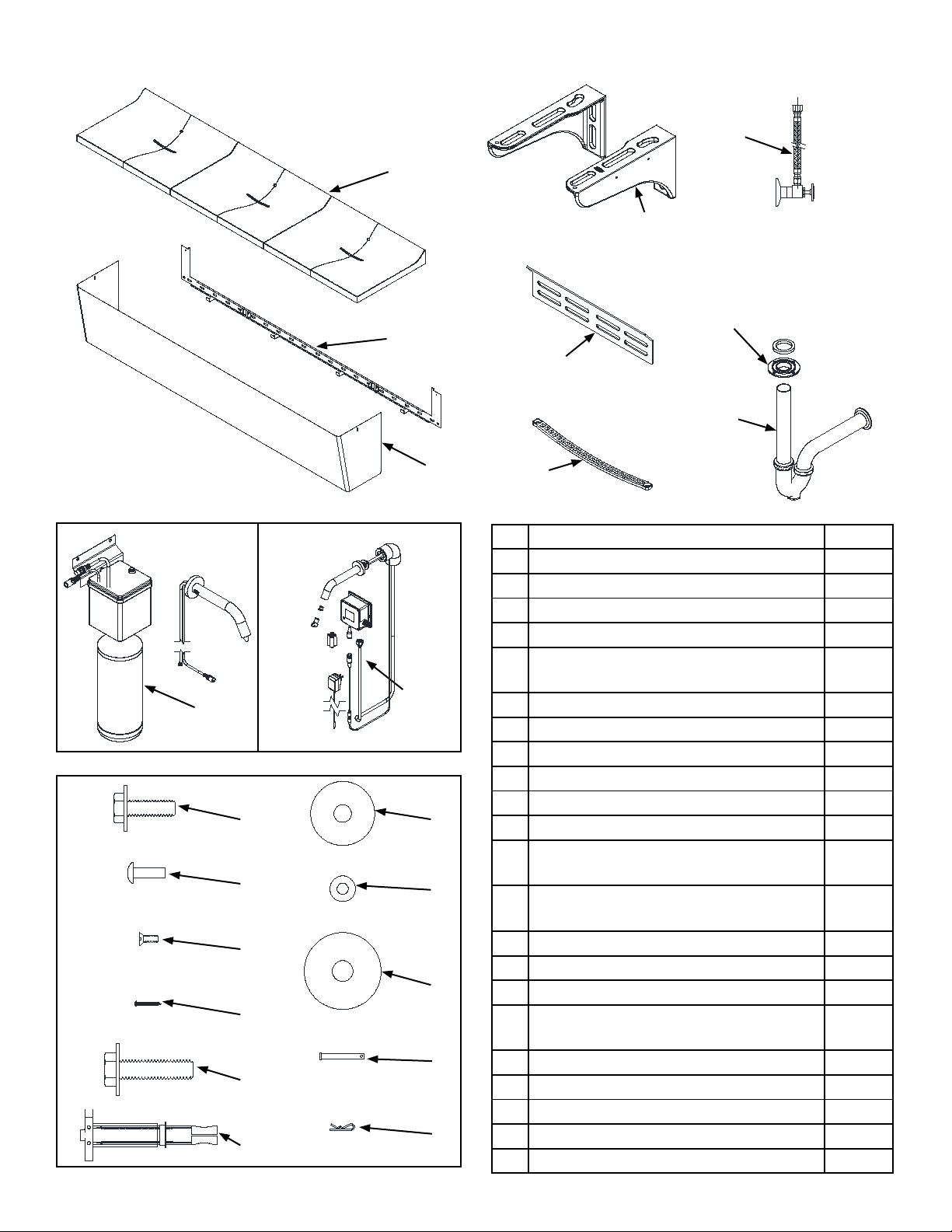
Sundara®Drift triple basin lavatory system manufactured by Zurn Industries. Lavatory shall be mounted at standard height to
conform with ANSI, UFAS, TAS and ADA Accessibility Standards. Counter and integral basin to be constructed of Sundara®
solid surface resin with aluminum trihydrate and other additives conforming to CSAB45.5/Z124 and IGC 156 standards.
Shroud enclosure is constructed of satin nished type 304, 18 gage stainless steel designed for easy access with vandal
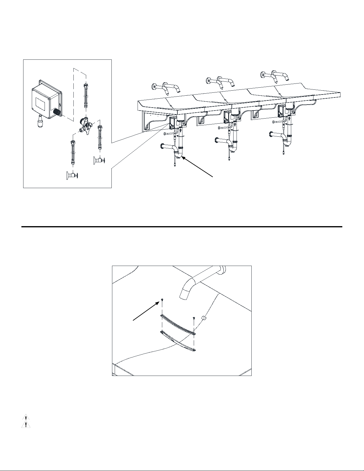
resistant hardware. Lavatory is furnished complete with 0.5 gpm laminar ow sensor operated faucet (specify model) and
optional liquid soap dispenser (specify model), ½” quarter turn supply stops, 3/8” exible supply risers, chrome 1 ¼” tail piece,
and chrome 1 ¼” p-trap for complete system operation.
Paired Faucet Typical Specication
(Refer to faucet manual for more details on specic model)
Voltage: 6 VDC Series [4 “AA” (Alkaline or Lithium) and/or external power option]
Sensor Range: Self-calibrated, dependent upon sink depth and nish.
Operating Water Pressure: 10-125 psi
Operational Water Temperature: 33°F to 140°F (1°C to 60°C)
Aerator: 0.5 GPM Vandal-Resistant (Standard)
Paired Soap Dispenser Typical Specication
(Refer to soap dispenser manual for more details on specic model)
Power Supply: AC 110 V; DC 6V
Soap Viscosity: 100-3800 cps
Operating Temperature: 340- 1310F
Typical Dispensed Volume: 1.25 ml
Be sure the sink/lavatory/basin is clear from any objects upon making the sensor to electronics connection initiating the self-
calibration feature. The sink must be clear of any and all objects in order to calibrate appropriately (calibration time approx 30-
60sec).
Prior to Installation:
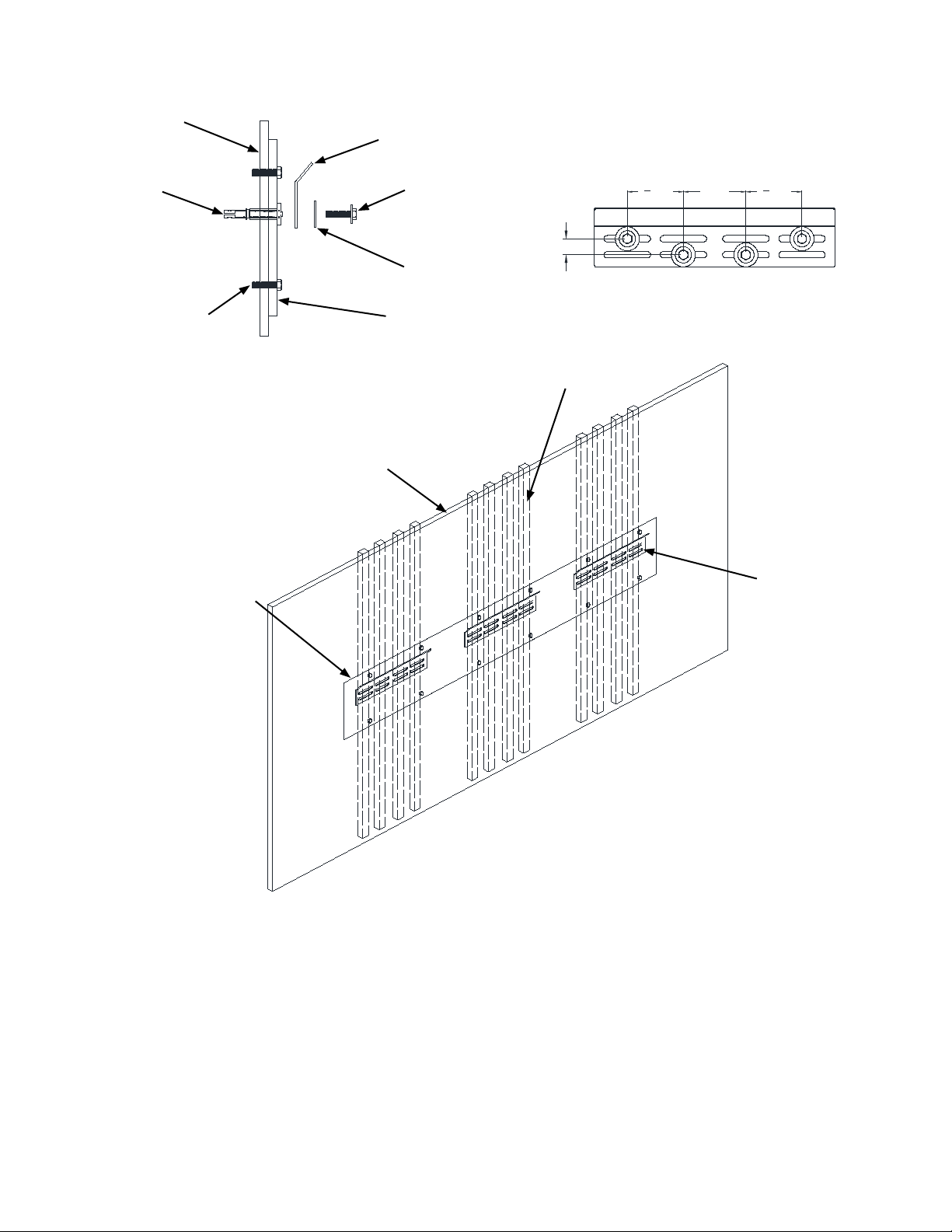
• If applicable, carrier (Z1240 series) is installed behind the wall.
• Hot and cold water supply lines are installed as per building codes.
• Care shall be taken when installing this product to prevent damage of any exposed or decorative surfaces.
• Measure the drain outlet from the oor.
Important Safety Information:
• Installer is responsible for ensuring the product is installed and conforms to all plumbing codes and ordinances.
• Do not convert or modify this Zurn product yourself. All warranties will be voided.
• Water supply lines must be sized according to building design in order to provide adequate water supply for each xture.
• Flush all water lines prior to making connections.
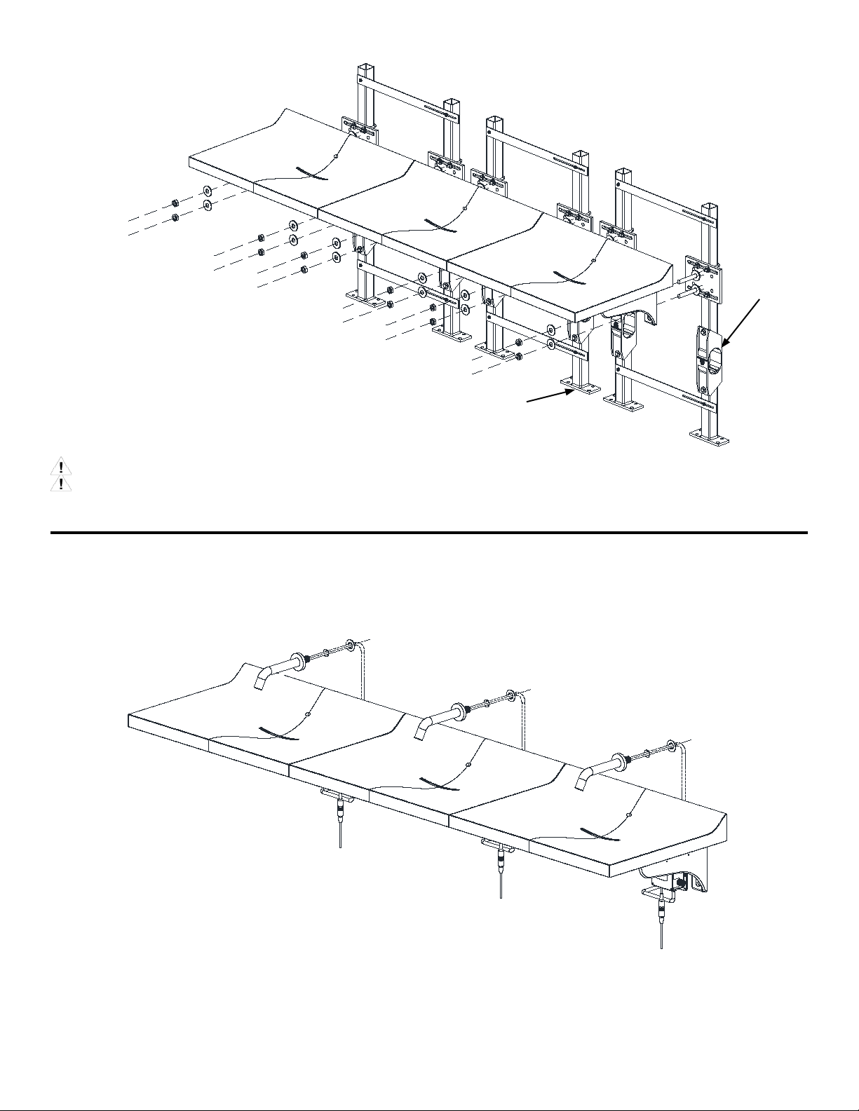
• Minimum 2 people required for the sink installation
• Au minimum, 2 personnes sont requises pour l’installation du lavabo.
S’assurer qu’aucun objet ne se trouve sur l’évier/le lavabo/le bac lors du branchement du capteur sur l’électronique, ce qui lance la
fonction d’auto-étalonnage. Rien ne doit se trouver sur le lavabo pour permettre son auto-étalonnage correct (temps
d’étalonnage de 30 à 60 s environ).

FV613 Rev. A 4/27/2018
Page 3
Z5003.03 Parts List
Optional
Item Name QTY
1 Basin 1
2 Shroud 1
3 Shroud Wall Bracket 1
4Mounting (L) Bracket 6
5 "Wall Hanger Bracket
(Available only for Retrot)" 3
6 Grid drain 3
7 Water Supply Items 6
8Drain Adapter Assembly 3
9P Trap Assembly 3
10 Sensor Faucet 3
11 Soap Dispenser (If Ordered) 3
12 "5/16-18 Screw for Mounting
L Bracket to Basin" 12
13 #10-24 Screw for Drain Adapter
and Shroud 14
14 #6-32 Screw for Grid Drain 6
15 Coarse Screw for Wall Bracket 2
16 Oversize 5/16 Washer 12
17 #10 Flat Washer for Drain Adapter
and Shroud 12
18 3/8-16 Hex Bolt with washer 33
19 3/8" Toggle Never Drop Anchor 39
20 3/8 Fender Washer 33
21 5/16" x 2 5/8" Clevis Pin 2
22 18-8 SS Hairpin Cotter 2
10
11
13
14
15
18
19
12
17
20
21
22
16
1
3
2
4
5
6
7
8
9

FV613 Rev. A 4/27/2018
Page 4
Plumbing and Electrical Rough-Ins
Note: InstallingtheP-trapoutletlowerthan19.5”fromnishedoorwillpreventthe
vandal shroud from being installed.
Note: Require a minimum of 1 anchor next to each pivot point to prevent execessive
exingwhenshroudisinfullyopenposition.

FV613 Rev. A 4/27/2018
Page 5
Drain Adapter Assembly Installation
L Brackets Installation
For ease of installation, lay basin on its top surface on a cushioned surface.
Use socket wrench to torque the screws (approximately 4-5 complete turns bottom out approximately 5 ft-lbs of torque).
Warning: Do not overtighten the screws.
Avertissement : ne pas trop serrer les vis.
For ease of installation, lay basin on its top surface on a cushioned surface.
Use T25 torx wrench to torque the screws (approximately 4-5 complete turns and squeeze the gasket,
approximately 2-3 ft-lbs of torque).
Warning: Do not overtighten the screws.
Avertissement : ne pas trop serrer les vis.
Socket Wrench:
5/16” & 3/8”
Torx Wrench:
T10 & T25
Non-toothed Wrench
Required Tools:
13
17
12
16

FV613 Rev. A 4/27/2018
Page 6
Retrotting Hanger Bracket Installation
Recommended for retrot:
• Measure the rough in dimensions on the wall. Top edge of the cutout marked must be 2” below the basin top back
edge.
• Cut the drywall to suitable size (90”x10”) and attach a minimum of 1/2” thick plywood to the wall stud and ush to the
drywall.
• Drill eight ¾” holes in the plywood at the locations shown in the graphic to the top. Then, install the supplied toggle
anchors to wall and secure the hanger bracket(s) directly to the plywood with the supplied bolts.
• Install hanger bracket to wall per structural rough-in. (Note: An offset might be necessary on applications using tile to
get the basin and mounting brackets ush with wall and mating to bracket)
• The plywood should not be visible after basin and shroud installation.
• The bracket needs to be checked for level after installation.
20
1819
Hanger
Bracket
Plywood
Wall Stud
Bolt supplied by
installer to attach
the plywood to
wall studs
1 [25]
31
2 [89]4 [99]31
2 [89]
1 [25]
3
1
2 [89]
4 [99]3
1
2 [89]
1 [25]
31
2 [89]
4 [99]
31
2 [89]
Wall Stud
Drywall
1/2” Thick
Plywood
Hanger
Bracket

FV613 Rev. A 4/27/2018
Page 7
Installing Mounting Bracket
• Secure the mounting bracket to the plywood cut-out with supplied washers, bolts and toggle an-
chors on the plywood.
Warning: Must be handled by at least 3 people
Warning: Ensure the basin back edge is completely supported in the wall bracket.
Avertissement : s’y prendre à trois minimum.
Avertissement : s’assurer que le bord arrière du bac est complètement soutenu par le support mural.
Mounting
Bracket
20
18
19
Plywood
Wall Stud
Bolt supplied by
installer to attach
the plywood to
wall studs

FV613 Rev. A 4/27/2018
Page 8
Installing with Carrier Option
Faucet Installation
Refer to faucet installation guide for details.
Warning: Must be handled by at least 3 people
Avertissement : s’y prendre à trois minimum.
Refer to Carrier Rough-in & Installation guide for details.
Optional
Wast Line
Sleeve (-WL)
Z1240-EZR
Carrier System

FV613 Rev. A 4/27/2018
Page 9
Soap Dispenser Bracket
and Bottle Installation
Refer to soap dispenser installation guide for details.
Soap Dispenser Installation
Install the soap spout on right or left as applicable.
Refer to soap dispenser installation guide for details.

FV613 Rev. A 4/27/2018
Page 10
P Trap Installation & Water
Supply Connection to Faucet
Adjust the tail piece base on drain outlet on the wall.
Grid Drain Installation
Use T10 Torx wrench to attach the grid drain to basin.
Torque screws until the screw heads are ushed with the screw pocket of grid drain.
Warning: Do not overtighten the screws.
Avertissement : ne pas trop serrer les vis.
Suggested Final Step: Caulk/Silicon lavatory to the nished wall for a water tight seal.
Connect the tail piece
to drain adapter
(threaded connection)
14

FV613 Rev. A 4/27/2018
Page 11
Shroud Installation:
• Align wall bracket as shown and install coarse screw on each side. Mark the slots in the wall bracket on the wall.
(Note: Anchors and bolts location can be exible base on on-site wall studs location)
(Note: A minimum of one anchor next to each pivot point is required to prevent excessive exing when shroud is in fully open
position)
Step 2
• Remove the wall bracket and drill 3/4” holes into the center of the holes previously marked. Ensure that wall studs are
not immediately behind the marked hole locations prior to drilling.
• Install anchor toggle bolts into previously drilled holes in walls.
• Re-install wall bracket with coarse screws in previous location. Then, fasten the wall bracket with 3/8” bolts through each
holes and into the toggle bolts.
Step 2
19
15
Pivot Point
Pivot Point
Step 3

FV613 Rev. A 4/27/2018
Page 12
Shroud Installation:
Step 4
Step 5
• Place shroud on hanger hooks of wall bracket as shown. Then, insert each clevis pin through the 2 pivot points. (Note: the
shroud will likely need to be rotated upward slightly in order to install each pivot.
• After one pivot is installed,retain clevis pins with the included cotter pins.
• Rotate the shroud up to the basin until the threaded hole in the L-bracket in visible through the slot in the shroud. Then, install
the screw shown, and repeat for the other side.
22
21
13

FV613 Rev. A 4/27/2018
Page 13
Maintenance Instructions:
• Do not use any abrasive or chemical cleaners to clean the sink, faucet and other components.
• If abrasives or chemicals are used it can lead to dulling of luster, attacking of chrome plating or decorative nishes.
• ONLY use mildly warm soapy water, and then wipe dry with a clean/soft towel or cloth.
• When cleaning other areas of the restroom be sure the sensor lenses are protected from other cleaning chemicals/
solvents to prevent potential damages to the sensor and/or electronics.
• For surface shine, rubbing a polishing agent will polish the surface of all components.
• Frequent proper cleaning of solid surface sink will maintain the gloss level over time. Also, darker colors require more
frequent cleaning and care. Dirt and residue can easily be removed from the basin surface by using water, mild soap
solution, household ammonia-based cleaners, and/or solid surface cleaners available in market.
• In order to remove hard water and difcult stains on basin surface, use a sponge with diluted cleaner to rub in a circular
motion. To disinfect basin surfaces, wipe the area with diluted bleach and then wash the surfaces and rinse with water.
• Avoid exposing solid surface basin with strong chemicals, such as acetone-based cleaners and solutions,. If surfaces
are exposed to these chemicals, quickly rinse the surface with water.
Repair Instructions:
• Zurn recommends that damages should be repaired by certied solid surface fabricator or repair agents.
• Blemishes to the basin surface (such as scratches, burn marks, and minor chipping) can be repaired by sanding with
super-ne(800 or 1000 grit) sand paper and/or maroon Scotch-Brite™ pads and then followed with a low-speed (1500-
2000 rpm) polisher with a wool pad and a solid surface cleaner or polish to buff the affected area.
• For more serious damage to the basin (size of a dime or larger), repair kits and instructions are available to purchase.
Contact customer service for further information on ordering.
Trouble Shooting Guide:
Service Parts:
Faucet Related Issues Refer to Faucet Manual included with faucet
Soap Dispenser Issues Refer to Soap Dispenser Manual included with soap dispenser
Part Number Part Description QTY
P5003-GD-PC Grid Drain Assembly for Drift Basin 1
P5000-DA Drain Adapter Assembly 1
P5000-WH Wall Hanger Assembly 1
P5000-BKT Mounting (L) Bracket Assembly for Reef Basin 1
P5003-SS1 Stainless Steel Shroud for Drift Basin 1
P5000-DA-BAG Drain Adapter 1
P5000-WH-BAG Wall Hanger Bracket Hardware Bag 1
P5000-BKT-BAG Mounting (L) Bracket Hardware Bag 1
P5003-SH Triple Shroud Hardware Bag 1
Table of contents
Other ZURN Washer manuals