manuals.online logo
Brands
  1. Home
  2. •
  3. Brands
  4. •
  5. Zuta
  6. •
  7. Musical Instrument Amplifier
  8. •
  9. Zuta z501 User manual

Zuta z501 User manual

1 x 1 Mic/Line Preamp.
Chassis: Aluminium, Black
1, Balanced Mic or Line Selectable
Impedance 1.2KΩ Balanced,
600Ω Unbalanced
Phantom 48VDC
Low Cut Filter 75Hz/12dB
Line Input Level 1V (0dBV) Balanced =
= 2V (+6dBV) Balanced Output,
Maximum Input 8V (+15dBV)
Mic Input Level 6-60dB Gain
Maximum Input 40mV (-27dBV)
1, Balanced Line
Impedance 300Ω Balanced,
150Ω Unbalanced
Line Output Level 1V (0dBV)In =2V (+6dBV)
Maximum Output 6V (15dBV)
Input Gain Control
Output Level Control
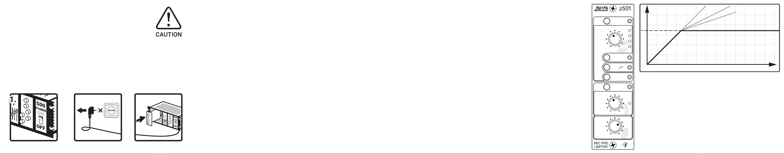
Output Limiter Threshold Adjust
Input Signal Green, 25mV On Threshold
Input Peak Red, -3dB Before Clip
Limiter Yellow, Output Limiter Activation
Frequency Response 20Hz - 20kHz (±1dB)
THD 0.06% & 1kHz
Signal to Noise 105dBV
Current required from +16V and -16V
Power Consumption 120mA Max
Dimensions: 1U in 500 series rack
Weight: 376 gr 13,3 oz
Description
Inputs
Outputs
Controls
Indicators
Electrical
Power
Congratulations and thank you for purchasing the z501.
This module was designed to inspire you and elevate the quality of your recordings
and to make it possible to reach your sonic goals faster and with ease. We
really went out of our way to bring you this refined quality and extremely clean
Swedish design using only the highest quality components and we also did
rigorous testing protocols on every unit to make sure it will perform perfectly in
every situation, in the studio, on the road or in a mobile recording environment.
Special attention was paid to ergonomics and also the visual language to
make sure that there will always be effective readability and visual feedback
supporting you in the most focus demanding and dynamic situations, to find
the right control fast makes you work better and saves time. We are confident
to say that our product is top tier. As any other of our devices , this one
requires very little care and just a little bit of attention to our recommendations
regarding maintenance. Please spend a couple of minutes to read this manual
so you can get the most out of the product. Remember and implement these
few recommendations for handling the product and you’ll be able to enjoy it for
many years to come.
We hope you will enjoy this product just as much as we enjoyed
designing and making it
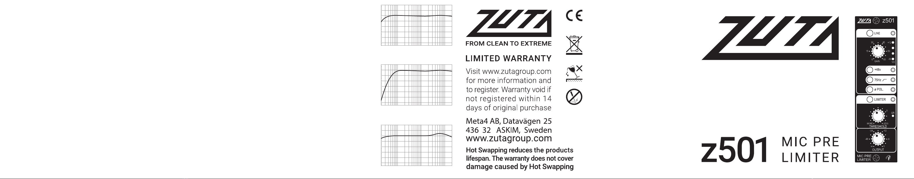
-25
+10
-20
-15
-10
-5
+0
+5
20 20k50 100200500 1k 2k 5k 10k
typical frequency response
-25
+10
-20
-15
-10
-5
+0
+5
20 20k50 100200500 1k 2k 5k 10k
typical frequency response with low cut
-25
+10
-20
-15
-10
-5
+0
+5
20 20k50 100200500 1k 2k 5k 10k
typical freq. response using standard “57” mic
SAFETY INFORMATION
- Pollution Degree 2
- Maximum Relative Humidity: <80%
- Operation temperature range: 10 °C to 35 °C
- Ordinary Protection: This equipment should
not be exposed to dripping or splashing.
- Avoid placing objects filled with liquids,
such as vases or glasses, on this equipment.
- Storage and transportation temperature
range –25 °C to 45 °C
- Equipment suitable for continuous operation
This product complies with the
(2012/19/EU) WEEE Directive. The affixed
product label indicates that you must not
discard this electrical/electronic
product in domestic household waste.
No user serviceable parts inside Refer
all servicing to qualified service personnel.
By affixing the CE marking to a product,
a manufacturer declares that the product
meets all the legal requirementsfor CE
marking and can be sold throughout the EEA.
Keep away from rain or moisture.
No dripping or splashing.
No objects filled with liquids
should be placed on or near the product.
INSTALLING THE MODULE
1. Power off
2. Unplug the 500 series rack frame from it’s power supply.
Visually inspect the slot you intend to use to make sure it is clean
and undamaged. Before touching the z501 module with your hands, make
sure you electrostatically discharge yourself by touching the 500 series rack.
3. Align the card edge connector with the card slot. Firmly and evenly push
the module into place until it is positively seated in the slot.
- Use the two supplied screws to mount the front panel to the 500 series rack.
- Plug in and turn on the power supply to the rack frame.
The module will automatically power up.
2.
UNPLUG
3.
MOUNTPOWER OFF
GAIN CONTROL Use the gain control to trim the level of the amplification of the input
signal. Too little, and you wont be able to hear anything, but too much and your signal
might go into clipping. Always follow the LED indicators for the signal level
and make sure that you are always below the red zone, or the red zone only light up
occasionally. To do fine-tuning and compress some peak values, use the limiter
(explained below).
LINE switch: switches between line and mic input level signal.
BASIC OPERATIONS
Before connecting any type of input device, first make sure
that the gain control is set to minimum. Also, make sure
that the settings on the module are switched properly for
the type of your input device (see functions below). Turn the
output level to 12 o’clock and add gain until you can clearly
hear the input signal. After this, you can use the various
controls to achieve the sound you like!
+48V Power supply for condenser microphones, turn this switch on ONLY for this
type of input devices.
ø POLARITY Regular function which rotates the signal for 180 degrees. Important –
not to be confused with phase shifting, this function only reverses the poles of the
output signal. For example, if you are recording a snare drum with two microphones,
one on top and one under the snare drum, you must rotate the polarity on one of the
microphones so the two signals don’t cancel each other out.
75Hz �This high pass filter is excellent for taming low frequencies from a mic, but
depending on your application, you can use this function on any input you want.
THRESHOLD Turning the THRESHOLD from MORE to LESS increases the value for the
signal level at which the limiter will be active when the LIMITER is ON.
LIMITER - a type of compressor designed for a specific purpose to limit the level of a
signal. The graph below shows a limiting ratio of infinity to one, i.e. there is no gain at all
above the threshold.
OUTPUT Attenuating the output level
Limit
Threshold
Input Level
Output Level
1:1
2:1
3:1
∞:1
LIMITER
MORE LESS
LINE
GAIN
+48v
75Hz
ø
POL.
THRESHOLD
OUTPUT
8
-48
6
15
30
-30
+12
45
50
0
60
VU
GR
-24 -12
-6
0
The silky smooth top end combined with the natural and warm sound
reproduction of the source material will never sound harsh with the z501.
The limiter is extremely smooth but yet very fast and effective in moderate
settings. But when used in extreme settings it will give you a sound with a burly
character. In light settings the Limiter reacts like a soft clip to protect the signal
from distorting and overloading the AD/DA converters or the tape recorders
alike. Since the unit is designed with a multi gain-stage topology, every
gain-stage is used to raise the gain in small amounts, leaving a tremendous
amount of headroom. The result is a very smooth sounding Mic Pre with a lush
and warm sound character. Perfect choise if you are looking for a natural
reproduction of the source material, the result will be a very musical and warm
soundscape. The z501 is especially well suited for smooth vocals. When serving
as the Mic Pre choice for the overhead mics for the drum kit it can tame even
harsh cymbals. When used on a string ensemble it will bring out the details
without sounding brittle and thin when replayed. It actually shines in every
situation and if a distorted sound character is preferred just add a distortion unit
to color the sound after the z501 in the signal chain. This will give you the
aggressive cut through sound when needed but with the full frequency spectra
in the foundation of the recorded source, resulting in a massive sound.
Legendary Ted Fletcher’s
MIC PRE & LIMITER
with multi gain-stage design

Popular Musical Instrument Amplifier manuals by other brands

Hughes & Kettner BASSBASE 250 instructions

Hughes & Kettner

Hughes & Kettner BASSBASE 250 instructions

ORANGE CRUSH 20RT manual

ORANGE

ORANGE CRUSH 20RT manual

HEADRUSH FRFR-112 user guide

HEADRUSH

HEADRUSH FRFR-112 user guide

Fender Rumble 15 owner's manual

Fender

Fender Rumble 15 owner's manual

Bugera 412F-BK user manual

Bugera

Bugera 412F-BK user manual

Fender Custom Vibrolux Service manual

Fender

Fender Custom Vibrolux Service manual

Peavey Rage 258 operating manual

Peavey

Peavey Rage 258 operating manual

Roland GC-405 owner's manual

Roland

Roland GC-405 owner's manual

Marshal Astoria Classic owner's manual

Marshal

Marshal Astoria Classic owner's manual

Marshall Amplification JVM2 Series owner's manual

Marshall Amplification

Marshall Amplification JVM2 Series owner's manual

Peavey PV i 8500 operating manual

Peavey

Peavey PV i 8500 operating manual

Tone King Imperial MK II user manual

Tone King

Tone King Imperial MK II user manual

Fender BLUES DE VILLE Service manual

Fender

Fender BLUES DE VILLE Service manual

Victory The Sheriff 44 user guide

Victory

Victory The Sheriff 44 user guide

Peavey Studio Pro 110 operating guide

Peavey

Peavey Studio Pro 110 operating guide

Laney LX 10 user manual

Laney

Laney LX 10 user manual

Roland JAZZ CHORUS owner's manual

Roland

Roland JAZZ CHORUS owner's manual

Peavey Tour TNT 115 operating manual

Peavey

Peavey Tour TNT 115 operating manual

manuals.online logo
manuals.online logoBrands
  • About & Mission
  • Contact us
  • Privacy Policy
  • Terms and Conditions

Copyright 2025 Manuals.Online. All Rights Reserved.