16XEIGHT SD2IEC evo2 User manual

16xEight
SD2IEC evo²
Installation
Instr uctions
Revision E3b

Wir danken für das uns mit dem Kauf dieses Produktes entgegengebrachte Vertrauen!
Unser Ziel ist es nicht nur die Anforderungen unserer Kunden zu erfüllen,
sondern diese stets auch zu übertreffen.
Wir wünschen Ihnen viel Freude mit dem Produkt und stehen bei etwaigen Problemen,
Fragen oder Anregungen zu unseren Geräten selbstverständlich gerne zur Verfügung.
Sie erreichen uns per e-Mail unter info(at)16xeight.de
Oder über das Kontaktformular auf unserer Homepage unter www.16xeight.de
Für den Einbau und die Inbetriebnahme dieses Bausatzes sind Fachkenntnisse der
Elektrotechnik sowie entsprechende handwerkliche Fähigkeiten erforderlich.
Sollten Ihnen diese fehlen so lassen sie den Einbau bitte von einer Person
mit entsprechendem Sachverständnis durchführen.
Für etwaige Schäden an Dingen oder Personen infolge unsachgemäßer Handhabung wird
keine Haftung übernommen!
Nachdruck oder Vervielfältigung jeglicher art, auch auszugsweise
nur mit vorheriger schriftlicher Genehmigung gestattet!
© 2014 16xEight
Version 1.1 Rev.E3b
Irrtümer und Änderungen vorbehalten.
Translated by
Dean Payne
-2-

1.1 Introduction
Read these instructions carefully before starting the installation
of the SD2IEC in your computer. Familiarise yourself with the connections and select a suitable
location from which to perform the installation.
Tools needed:
• Phillips Screwdriver
• File
• Small drill and drill bits
• Side cutters
• Small needle-nose pliers
• Soldering iron (approx. 30w) with a fine tip
1.2 Overview - Connections and Controls
-3-
1 Installation
Fig. 1.1

Pin Wire Colour Signal
1 Black G ound (GND)
2 B own +5V Supply Voltage (VCC)
3 Red IEC-ATN
4 O ange IEC-DATA
5 Yellow IEC-CLOCK
1.3 Installation
Switch off your C64 and any attached devices and disconnect it from all cables.
Turn the C64 on its top and remove the three case screws at the front edge. Turn the C64 back
over and open it carefully by lifting the housing to the front edge under the keyboard.
Take care that the locking lugs on the rear side of the case do not break.
Depending on model version, disconnect the keyboard and power ED
from the C64 mother board.
Remove the keyboard and the shielding plate, if necessary, so that after removing the fixing
screws, the exposed motherboard can be removed.
Now, turn the motherboard over and solder
the corresponding three lines of the IEC
supplied connecting cable to the IEC connector
points.
The assignment of the connectors on the C64 and
the SD2IEC are shown in the diagrams and table
on the right:
The cassette port can be used to connect the
power supply line (VCC) and ground line (GND),
as follows:
-4-
Double check that the correct connections have been made before refitting the motherboard back
into the case.
Caution:
Ensure the connecting cable is positioned carefully
to avoid creasing and possible damage.
Fig. 1.2
Fig. 1.3

The DiskChange and Reset buttons can now be
installed, if desired, by using the supplied cable
and connecting the corresponding wires to the
CTR interface on the SD2IEC board as shown
below.
Make sure that the unused wires are carefully
isolated to ensure that the no short circuits can
arise!
-5-
When using an CD status display, contrast adjustment must be made before refitting the case.
To do this, connect the C64 to the power supply and turn it on. Now, with a small screwdriver,
turn the contrast potentiometer on the SD2IEC circuit board until the display is easy to read.
You can now reassemble the C64 in reverse order and start commissioning the device.
ID DIP 1 DIP 2
8 OFF OFF
9 ON OFF
10 OFF ON
11 ON ON
DIP-Switch Positions for Device ID 8-11
The optional CD status display may now be installed in a suitable position.
Assembly of the device may be completed. Connect the power cable ED, CTR interface and op-
tional CD display to the appropriate connectors on the SD2IEC board.
Select the device address for the SD2IEC
using the dip switches located on the
SD2IEC circuit board. The following dia-
gram shows the corresponding device
number and switch positions.
(This can also later be permanently
changed directly from the C64)
Fig. 1.4
Fig. 1.5

2 Commissioning
2.1 Functional Test
First, a function test should be carried out to ensure that the SD2IEC has been properly
connected to the C64.
Place a FAT formatted SD card into the SD2IEC.
After the C64 has been switched on, at the flashing cursor type OAD "$", 8 <return>
The contents of the SD card should be listed on the screen.
If an error message like ?DEVICE NOT PRESENT ERROR or ?FI E NOT FOUND ERROR
occurs, please read section 2.3 for fault isolation.
2.2 Setting the Real Time Clock
The following command can be used in direct mode to set the date and time for the real time
clock after initial commissioning or after changing the RTC battery:
OPEN 15,8,15, "T-WA <weekday> <month> <year> <hour> <minute> <second> <AM/PM>" + CHR $ (13): C OSE 15
For the weekdays, please use the following notation:
SUN. - MON. - TUES - WED. - THUR - FRI. - SAT.
Example for Monday, 28/10/2013 at 10:30 clock in the morning:
OPEN 15,8,15, "T-Wamon. 10/28/13 10:30:00 AM "+ CHR $ (13): C OSE 15
The commissioning of the SD2IEC is complete.
-6-

Symptom Cause Remedy
ED does not light up, the connected display re-
mains dark and attempting to load the directory
from the SD2IEC results in a
?DEVICE NOT PRESENT ERROR
No supply voltage to SD2IEC. Check connections from the SD2IEC to the C64,
in particular, the lines for VCC and Ground (GND).
The SD2IEC seems to initialize itself, the optional
CD display shows the READY: message,
but ? DEVICE NOT PRESENT ERROR appears
during the loading test or the C64 hangs
completely.
The device address is set incorrectly or the con-
nections on the IEC connector are
incorrect.
Check the setting of the device address.
Check the connecting cable solder joints at the
C64 IEC socket are clean and correctly assigned.
Attempting to load the directory from the SD2IEC
results in a ? FI E NOT FOUND ERROR and a
flashing ED.
The SD card is incorrectly formatted. In rare cases,
the SD card is incompatible.
If possible, format the SD card in FAT32 format
without the quick format option or use an SD card
formatter tool.
Alternatively, use another SD card.
The SD2IEC works, but the optional CD display
shows nothing.
The contrast is not set correctly or the display con-
nector is not properly inserted.
Adjust the contrast using the
potentiometer on the SD2IEC board.
Check that the display connector is correctly posi-
tioned
The ED blinks immediately after switching on and
the SD2IEC does not work properly.
Faulty connection of the disk change button or the
button is permanently suspended.
Check the connection of the DiskChange button
and the push-button itself. You can
test the DiskChange function of the SD2IEC tem-
porarily by manually touching the stripped ends of
the relevant wires together on the CTR cable.
2.3 TROUB ESHOOTING
In the table below you can find common errors and their causes
which will help to eliminate problems.
If the problem is not rectified after following the remedies listed, please get in touch with us.
-7-
2.4 FIRMWARE UPDATES
To make firmware updating as easy as possible, a boot loader is used.
Copy the new version of the firmware to the root directory of an SD card and insert it.
The boot loader will automatically detect the new firmware and writes it into the Flash memory of
the controller. This process is indicated by rapid flashing of the ED.
.
CAUTION: Only use the firmware images available on our website!
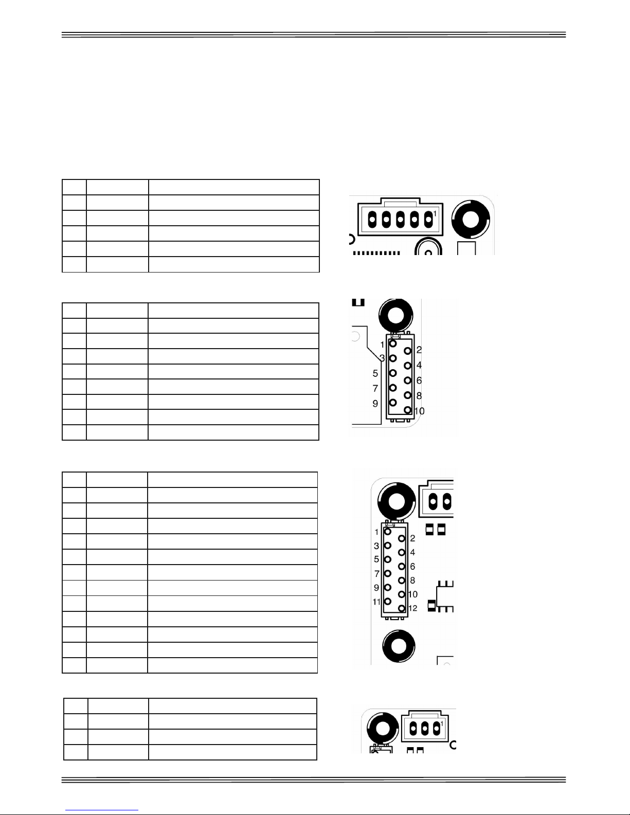
ANNEX A
The tables below show the pin assignments of the SD2IEC interface.
Pin Wire Colour Signal
1 Black G ound (GND)
2 B own +5V Supply Voltage (VCC)
3 Red IEC-ATN
4 O ange IEC-DATA
5 Yellow IEC-CLOCK
Pin Wire Colour Signal
1 B own G ound (GND)
2 Red Expansion TxD
3 O ange Expansion RxD
4 Yellow SD2IEC Reset
5 G een Diskchange Next
6 Blue Diskchange P ev
7 Violet Device ID0
8 G ey Device ID1
Pin Wire Colour Signal
1 Black G ound (GND)
2 White VCC +5V
3 G ey Cont ast Voltage
4 Violet LCD RS
5 Blue LCD RW
6 G een LCD E
7 Yellow LCD D4
8 O ange LCD D5
9 Red LCD D6
10 B own LCD D7
11 Black Backlight Anode
12 White Backlight Cathode
Pin Wire Colour Signal
1 Black LED Busy (+)
2 B own G ound (GND)
3 Red LED E o (+)
IEC / POWER
CTR
CD
ED
-8-
Fig. A.1
Fig. A.2
Fig. A.3
Fig. A.4
Table of contents


