2N Telekomunikace NetSpeaker User manual

2N®NetSpeaker
Audio Decoder with Amplifier
User Manual
Version 1.0.0
Firmware 1.0.0 www.2n.cz

The 2N TELEKOMUNIKACE joint-stock company is a Czech manufacturer and supplier of
telecommunications equipment.
The product family developed by 2N TELEKOMUNIKACE a.s. includes GSM gateways,
private branch exchanges (PBX), and door and lift communicators. 2N TELEKOMUNIKACE
a.s. has been ranked among the Czech top companies for years and represented a
symbol of stability and prosperity on the telecommunications market for almost two
decades. At present, we export our products into over 120 countries worldwide and have
exclusive distributors on all continents.
2N®is a registered trademark of 2N TELEKOMUNIKACE a.s.. Any product and/or other
names mentioned herein are registered trademarks and/or trademarks or brands
protected by law.
2N TELEKOMUNIKACE administers the FAQ database to help you quickly find information
and to answer your questions about 2N products and services. On faq.2n.cz you can find
information regarding products adjustment and instructions for optimum use and
procedures “What to do if...”.
Declaration of Conformity
2N TELEKOMUNIKACE hereby declares that the 2N®SIM Star product complies with all
basic requirements and other relevant provisions of the 1999/5/EC directive. For the full
wording of the Declaration of Conformity see the CD-ROM enclosed and at www.2n.cz.
The 2N TELEKOMUNIKACE company is the holder of the ISO 9001:2000 certificate. All
development, production and distribution processes of the company are managed by this
standard and guarantee a high quality, technical level and professional aspect of all our
products.

Contents
1. Product Overview...............................................................5
1.1 Product Description....................................................................................................... 6
Basic Features.................................................................................................................. 6
Optional Accessories........................................................................................................ 7
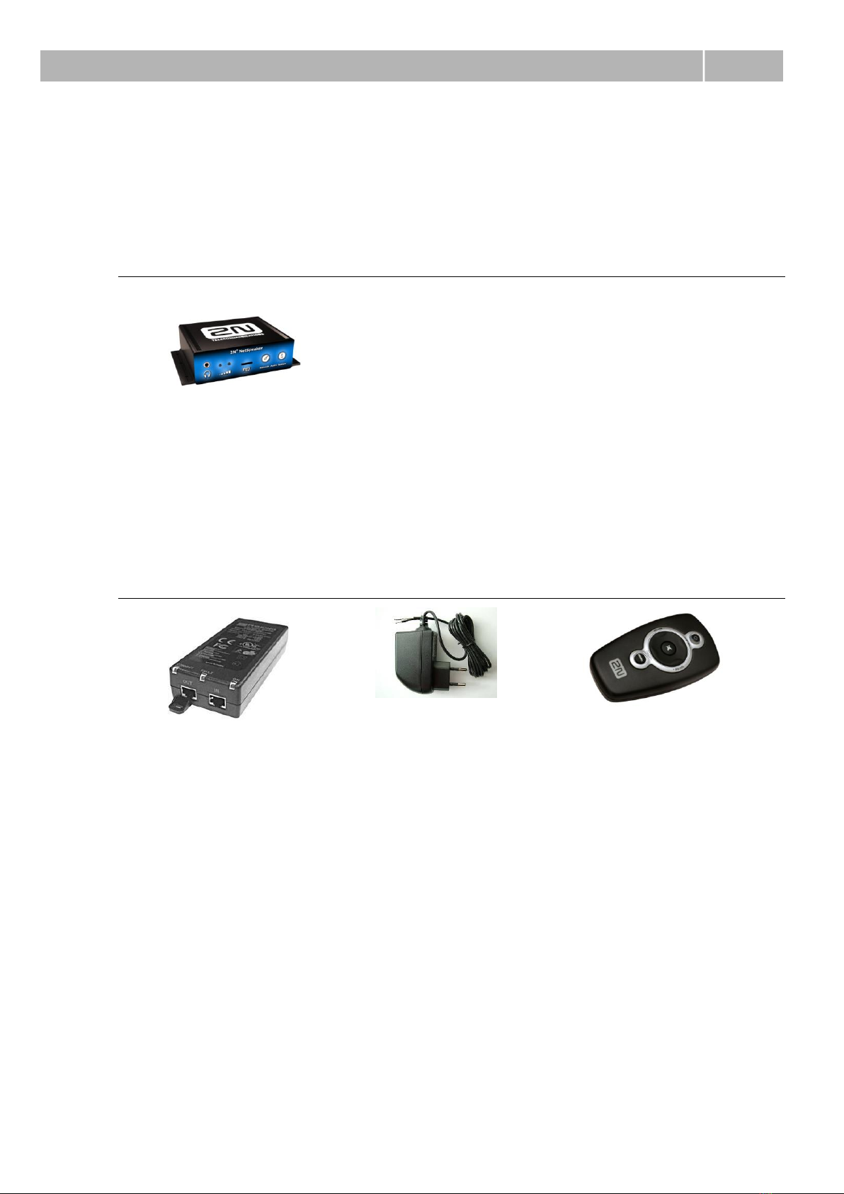
1.2 2N®NetSpeaker Components and Associated Products........................................... 8
Basic Unit ......................................................................................................................... 8
Accessories...................................................................................................................... 8
Associated Products......................................................................................................... 9
1.3 Changes in Documentation......................................................................................... 10
1.4 Terms and Symbols Used ........................................................................................... 11
Symbols Used in Manual................................................................................................ 11
Future Functions and Features...................................................................................... 11
2. Description and Installation............................................13
2.1 Product Description..................................................................................................... 14
2N®NetSpeaker Front and Back Panels........................................................................ 15
2.2 Before You Start........................................................................................................... 16
Product Completeness Check........................................................................................ 16
Installation Conditions .................................................................................................... 16
2.3 Mounting ....................................................................................................................... 17
Surface Mounting ........................................................................................................... 17
2.4 Electric Installation ...................................................................................................... 18
Electric Installation Step by Step.................................................................................... 18
Loudspeaker Connection ............................................................................................... 18
Headphone/External Amplifier Connection .................................................................... 19
Digital Ouput Use ........................................................................................................... 19
Digital Input Use............................................................................................................. 19
Memory Card Use .......................................................................................................... 20
LAN Connection ............................................................................................................. 20
Power Supply Connection.............................................................................................. 21
3. 2N®NetSpeaker Configuration .......................................23
3.1 2N®NetSpeaker Configuration.................................................................................... 24
Default Setting................................................................................................................ 24
Basic Parameter Settings............................................................................................... 25
Firmware Upgrade.......................................................................................................... 28
Firmware Installation ...................................................................................................... 28
4. Function and Use.............................................................29

4.1 Basic Functions............................................................................................................ 30
2N®NetSpeaker Button Control..................................................................................... 30
2N®NetSpeaker Remote Control................................................................................... 30
2N® NetSpeaker Status Signalling.................................................................................. 31
5. Technical Parameters......................................................33
5.1 Technical Parameters .................................................................................................. 34
Mechanical and Electrical Parameters........................................................................... 34
6. Supplementary Information ............................................37
6.1 List of Abbreviations.................................................................................................... 38

5
1
1. Product
Overview
In this section, we introduce the 2N®NetSpeaker product, outline its application
options and highlight the advantages following from its use. The section also includes
safety precautions.
Here is what you can find in this section:
Product Description
Associated Products
Changes in Documentation
Terms and Symbols Used

Product Description
1.1
6
1.1 Product Description
The 2N®NetSpeaker System is a universal sound transmission system for IP
networks. Its purpose is to replace classic wire broadcasting systems using a
broadcast centre, obsolete 100V analogue circuits and loudspeakers. It finds a variety
of applications - in schools, hospitals, office buildings, hotels, production halls,
shopping centres, bus terminals, airports and so on. Compared with the classic
analogue solution, the system has a lot of advantages: uses the existing LAN
infrastructure, provides easy connection to vast or remote areas, helps users send
anything from anywhere to any place, shows no zone or sound source limitations and,
in general, is very flexible and easily extendable.
2N®NetSpeaker is a stand-alone sound decoder and converter with an amplifier
working as a terminal audio device for the 2N®NetSpeaker System. 2N®NetSpeaker
communicates with the 2N®NetSpeaker System via the local area network (LAN),
decodes the audio stream converting it into an analogue signal, which is then
amplified by an integrated power amplifier.
2N®NetSpeaker is available in two versions:
Module with an amplifier (Part No. 914010E), which can be connected to an
external loudspeaker/an external amplifier or used with headphones.
Module with an amplifier and a loudspeaker (Part No. 914020E), designed for
direct wall mounting (wall/flush/ceiling mounting).
This User Manual applies to Part No. 914010E.
Basic Features
10/100Base-TX LAN interface
12V DC/2A or PoE 802.3af power supply
Integrated 14W STEREO/MONO amplifier
Line/headphone output
Colour LED operation status indicators
Universal galvanically isolated output
Universal digital input
MicroSD card slot
Two universal programmable buttons
Infrared remote control

Product Description
1.1
7
Optional Accessories
12V DC/2A Power Supply Adapter
Universal power supply adapter for 2N®NetSpeaker. With it, you can make
the best of the integrated amplifier power.
PoE 802.3af Injector
Universal PoE injector for the 2N®NetSpeaker power supply. Useful for places
where 12V power supply is unavailable or a 12V adapter cannot be used.
Remote control
Infrared remote control for comfortable volume or channel adjustment.

2N® NetSpeaker Components and Associated Products
1.2
8
1.2 2N®NetSpeaker Components and
Associated Products
Basic Unit
914010E
2N®NetSpeaker with
Amplifier
Accessories
91378100
PoE Injector
914102E
12V DC/2A Adapter
914101E
Remote Controller

2N® NetSpeaker Components and Associated Products
1.2
9
Associated Products
914020E
2N®NetSpeaker with
Loudspeaker for Soffit
Mounting
914110E
Flush Mounting Box
914120E
Wall Mounting
Box

Changes in Documentation
1.3
10
1.3 Changes in Documentation
The manufacturer reserves the right to modify 2N®NetSpeaker in order to improve its
qualities.
Manual
Version
Changes in Documentation
1.0.0
The User Manual corresponds to 2N®NetSpeaker FW version
1.0.0.
Caution
The manufacturer keeps improving the firmware according to the clients’
requirements. Refer to the 2N web sites www.2n.cz for the current
2N®NetSpeaker firmware and User Manual versions.

Terms and Symbols Used
1.4
11
1.4 Terms and Symbols Used
Symbols Used in Manual
Safety Warning
Always abide by this information to prevent injury of persons.
Warning
Always abide by this information to prevent damage to the device.
Caution
Important information for system functionality.
Tip
Useful advice for quick and efficient functionality.
Note
Routines or advice for efficient use of the device.
Future Functions and Features
The grey-marked text in this document designates the functions and features that are
under preparation or development at present.


13
2
2. Description and
Installation
This section describes the 2N®NetSpeaker product and its installation.
Here is what you can find in this section:
Product Description
Before You Start
Mounting

Product Description
2.1
14
2.1 Product Description
2N®NetSpeaker is a LAN audio converter designed for public sound distribution
through the 2N®NetSpeaker System. It is connected to the 2N®NetSpeaker System
via the local area network (LAN). It communicates with the 2N®NetSpeaker Server,
receives the audio stream, decodes it and converts it into an analogue signal.
2N®NetSpeaker is equipped with an integrated 14W amplifier for direct loudspeaker
connection.
2N®NetSpeaker can be controlled by two front panel buttons or an infrared remote
controller.
2N®NetSpeaker is equipped with a digital input and output, which extend the
converter options and may be helpful in special applications.
2N®NetSpeaker helps you extend the internal FLASH memory using MicroSD memory
cards.
Use the integrated Telnet server to make basic settings for connection of 2N®
NetSpeaker into the LAN (refer to the Basic Parameter Settings). Apply the 2N®
NetSpeaker Software for configuration and use of all functions (refer to the
2N®NetSpeaker Software User Manual).

Product Description
2.1
15
2N®NetSpeaker Front and Back Panels
Fig. 2.1 - 2N®NetSpeaker Front Panel
Fig. 2.2 - 2N®NetSpeaker Back Panel
1. 12V DC/2A power supply adapter connector
2. Alternative power supply connection terminals
3. Relay output with galvanic isolation for external 24V/1A AC/DC load switching
4. Digital input (without galvanic isolation) for external sensor/button, etc.
5. 10/100BASE-TX LAN RJ-45 connector
6. Integrated amplifier output terminals for 1 or 2 loudspeakers
7. RESET button
8. Headphone/line output for standard headphones/external amplifier
9. Universal buttons with programmable functions
10. MicroSD card slot for higher internal memory capacity
11. Operational status colour LED indicators
12. Infrared signal receiver for remote control

Before You Start
2.2
16
2.2 Before You Start
Product Completeness Check
Before installing this product, check whether the product delivery includes:
1 2N®NetSpeaker
2 wall mounting L-profiles
4 6mm dowels
4 3.5x35mm screws
4 self-adhesive device feet
1 5-pin terminal block
1 4-pin terminal block
Quick User Manual
CD-ROM with User Manual and Software
Certificate of Warranty
Installation Conditions
2N®NetSpeaker is to be connected to the LAN.
2N®NetSpeaker is designed for indoor use.
2N®NetSpeaker may not be operated in damp environments.

Mounting
2.3
17
2.3 Mounting
If you intend to use your 2N®NetSpeaker unit in various interiors, please stick the
four feet included in the delivery onto the bottom side of the device to avoid
scratching of the underlying surface.
Surface Mounting
Use the included L-profiles to mount your 2N®NetSpeaker unit on a wall or another
solid surface. Insert the L-profiles in the sides of the assembly and fit them with four
screws to keep the device in place. You can use the dowels and screws included in the
delivery. Follow the instructions below while drilling the mounting holes.
Fig. 2.3 –Mounting Holes

Electric Installation
2.4
18
2.4 Electric Installation
Electric Installation Step by Step
It is very easy to connect 2N®NetSpeaker electrically. Follow the steps below to avoid
equipment damage or electrical injury:
Connect a loudspeaker, headphones or an external amplifier.
Connect the digital input and output.
Insert the MicroSD card.
Connect the UTP cable.
Connect a 12V power supply (unless PoE is used).
Caution
Be sure to connect the 2N®NetSpeaker power supply as the last step. The
same applies to PoE supply from the LAN.
Loudspeaker Connection
2N®NetSpeaker is equipped with a power amplifier for 1 (MONO) or 2 (STEREO)
loudspeakers. The loudspeakers to be used must have the nominal impedance of 4-
16Ω. Possible configurations and related maximum power outputs (sinus, THD < 1%)
are included in the table below:
Loudspeaker(s)
12V/2A
PoE
2 x 4Ω STEREO
2 x 2.5W
2 x 2.5W
2 x 8Ω STEREO
2 x 7W
2 x 4W
2 x 16Ω STEREO
2 x 4W
2 x 4W
4Ω MONO
1 x 14W
1 x 8W
8Ω MONO
1 x 8W
1 x 8W
Use the 2N®NetSpeaker back panel terminals marked L + and L –for the left channel
and R + and R –for the right channel. Use the left channel terminals for the MONO
mode.

Electric Installation
2.4
19
Headphone/External Amplifier Connection
2N®NetSpeaker is equipped with a headphone/external amplifier connector. The
3.5mm jack is available on the front panel.
Digital Ouput Use
2N®NetSpeaker is equipped with a relay switch for light signalling/external
amplifier/alarm/activation. The output is available on terminals marked LOGIC OUT
and allows for switching of up to 24V/1A AC/DC loads.
Program the output either to the N/O (normally open) or N/C (normally closed) mode.
Warning
Do not exceed the upper voltage and current limits to avoid irreversible
damage of the equipment.
Note
The current 2N®NetSpeaker FW version does not support this function.
Refer to www.2n.cz for 2N®NetSpeaker FW updates. Contact the 2N
TELEKOMUNIKACE Technical Support staff please for more information.
Digital Input Use
2N®NetSpeaker is equipped with a digital input for an optional button, sensor of
movement or other applications. This input is available on the LOGIC IN terminal. Up
to 5 to 24V DC voltage can be applied to the input against the ground terminal
marked DC IN -.

Electric Installation
2.4
20
Warning
Do not exceed the maximum voltage values (24V) applied to the LOGIC
IN input to avoid irreversible damage of the equipment.
Note
The current 2N®NetSpeaker FW version does not support this function.
Refer to www.2n.cz for 2N®NetSpeaker FW updates. Contact the 2N
TELEKOMUNIKACE Technical Support staff please for more information.
Memory Card Use
2N®NetSpeaker is equipped with a MicroSD card slot for storing music or voice in case
the equipment is not connected to the LAN permanently or temporarily.
The MicroSD card slot is available on the 2N®NetSpeaker front panel.
Note
The current 2N®NetSpeaker FW version does not support this function.
Refer to www.2n.cz for 2N®NetSpeaker FW updates. Contact the 2N
TELEKOMUNIKACE Technical Support staff please for more information.
LAN Connection
2N®NetSpeaker can be connected to a standard local area network using a LAN
interface via the RJ-45 connector on the back panel. Always use CAT-5d or higher
class cables for reliability reasons.
Table of contents