•
•
•
•
•
•
•
•
•
•
•
•
•
•
•
•
•
•
1. Product Introduction
In this section, we introduce the 2N®LiftIP product, outline its application options and highlight
the advantages following from its use.
Here is what you can find in this section:
1.1 Product Description
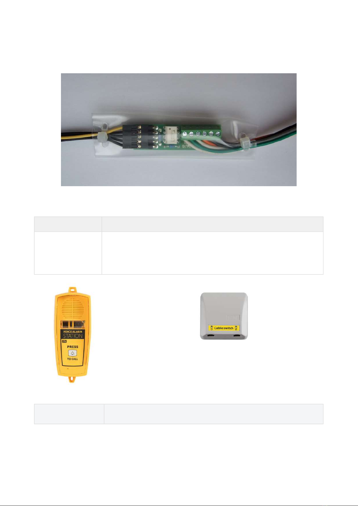
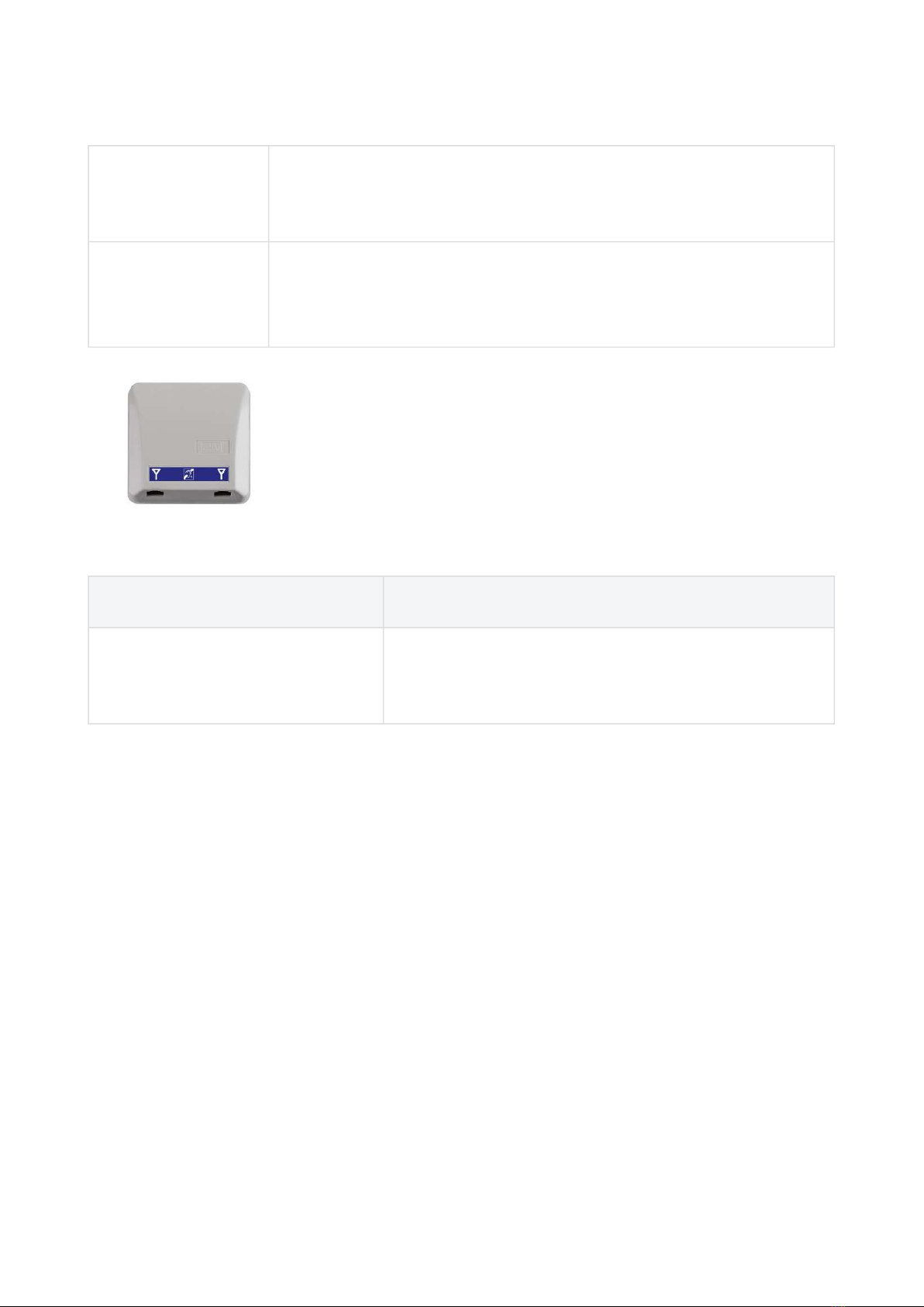
1.2 Components and Associated Products
1.3 Upgrade
1.4 Terms and Symbols
1.1 Product Description
Basic Features
2N®LiftIP is primarily designed for sites where a LAN is available.
2N®LiftIP is a Speakerphone on principle. This means that a microphone and a speaker
built-in behind the lift button panel are used for bidirectional communication.
Connect 2N®LiftIP to your LAN using an RJ-45 connector. Feed 2N®LiftIP either from an
external 10–30 V DC / 0.5 A power supply or directly from the LAN if equipped with PoE
802.3af supporting elements.
2N®LiftIP can only be used for making calls to pre-programmed numbers and cannot be
misused for “calling at someone else's account".
Connection of an almost unlimited count of communicators is a great advantage.
Advantages of Use:
Basic announcement set playing
Optimum acoustic properties
Adjustable speaker volume via audio unit buttons (during a call)
Recording of up to 8-minute long announcements (10 user messages)
Recording of user digits in a language other than that of the voice menu
Check call function once in 3 days (programmable)
Function indication – two LEDs meeting the applicable lift regulations
Easy control and configuration – voice menu
Setting option via the Service Tool application
•
Caution
This product, its installation and configuration are not intended for persons with
physical, sensory or mental disabilities or persons with limited experience and
skills unless expert supervision or relevant instructions are provided to them by a
person responsible for their safety.