2Power 2P 400l User manual

Agiba Heating
Frjentsjerterdyk 1
8855 XC Sexbierum
www.agibaheating.nl
2Power storage tank
Installation instructions
This installation construction contains important advice for handling, installing and starting up a
2Power solar plant. Read these advice carefully before mounting. The mounting and the start-up have
to be conducted by a permitted specialized company. With an improper installation the guaranty
expires.

Pagina 2 ǀ8
InstAnl.V08-2014-0
1. General
Pay attention to the following symbol for important relevant information.
1.1. Working principle/ description of the device
The device combines a hygienic heating of water and a multivalent stratified storage for the
storing of solar heat as well as heat from other heating systems like heat pumps, biomass- or
pellet boilers. The drinking water is heated in a continuous flow by a stainless steel smooth
pipe heat exchanger. The volume of the storage serves as an energy storage for the heating
of the drinking water as well as the operation of the heating and is additionally heated by
solarthermal energy through a heat exchanger of copper fins
The sleeve patterns and numbers, as well as the pipe registers and the solar heat exchanger
allow a multivalent operation. Also, the storage provides the possibility of a continuous sensor
strip at any level of the storage to sense the temperature. The associated thermal insulation
of the storage protects the tank against heat loss.
1.2. Intended use
The described 2Power storage tank is provided for the storing of heating water and the
heating of the drinking water. Any use which goes beyond these limits is not regarded as the
intended use. The intended use also includes the observance of this instruction as well as the
instrunctions of the used supplies.
With changing or reconstructing the tank the guaranty expires.
2. Safety
Please follow these safety notes strictly to exclude danger and damages to people and
material assets.
For more clarity, symbols and warning signs are attached to the listed notes in this installation
instruction. These symbols and warnings will help to ensure your personal safety, the safety
of third parties and to avoid property damage.
Severe personal injury or substantial property damage can occur
If proper precautions are not taken.
Also follow the safety instructions of all other components that are installed in the heating
system.
At outlet temperatures of more than 43 ° C there is a risk of scalding.

Pagina 3 ǀ8
InstAnl.V08-2014-0
2.1. Regulations and guidelines
Follow the relevant accident prevention regulations, environmental regulations and statutory
rules for assembly, installation and operation, as well as the relevant safety regulations of
DIN, EN, DVGW, VDE and VDI and any national standards, laws and regulations.
The electrical wiring work may only be carried out by qualified electricians. The rules as well
as the guidelines of the competent power supply company have to be kept.
The hydraulic connection work may only be carried out by qualified personnel. The valid rules
and regulations have to be kept.
2.2. Transport
The storage may only be transported upright!
For transporting you can use the hooks on the top of the tank.
At the receiving, the storage and accessories must be checked for possible
transport damage. Neither the manufacturer nor the supplier is liable for shipping
damages, but the freight carrier. After the acceptance of goods without objections
transport damages can no longer be asserted.
3. Installation
The installation, start-up, as well as maintenance and repair of the device may only
be carried out by an expert technician. A safety valve is necessary at the cold water
pipe. The device has to be run with pressure fittings.
3.1. Site
Be sure that the floor is stable
Be sure that the floor is even
Pay attention to ceiling height and tilted dimensions (see chapter 5: “Technical Data”)
3.2. Insulation
Place the device at its location and align it according to the installation. At this pay attention
to sufficient assembly freedom. Then assemble the insulation. After assembling the insulation
you can start with the integration to the heating and hot water system.
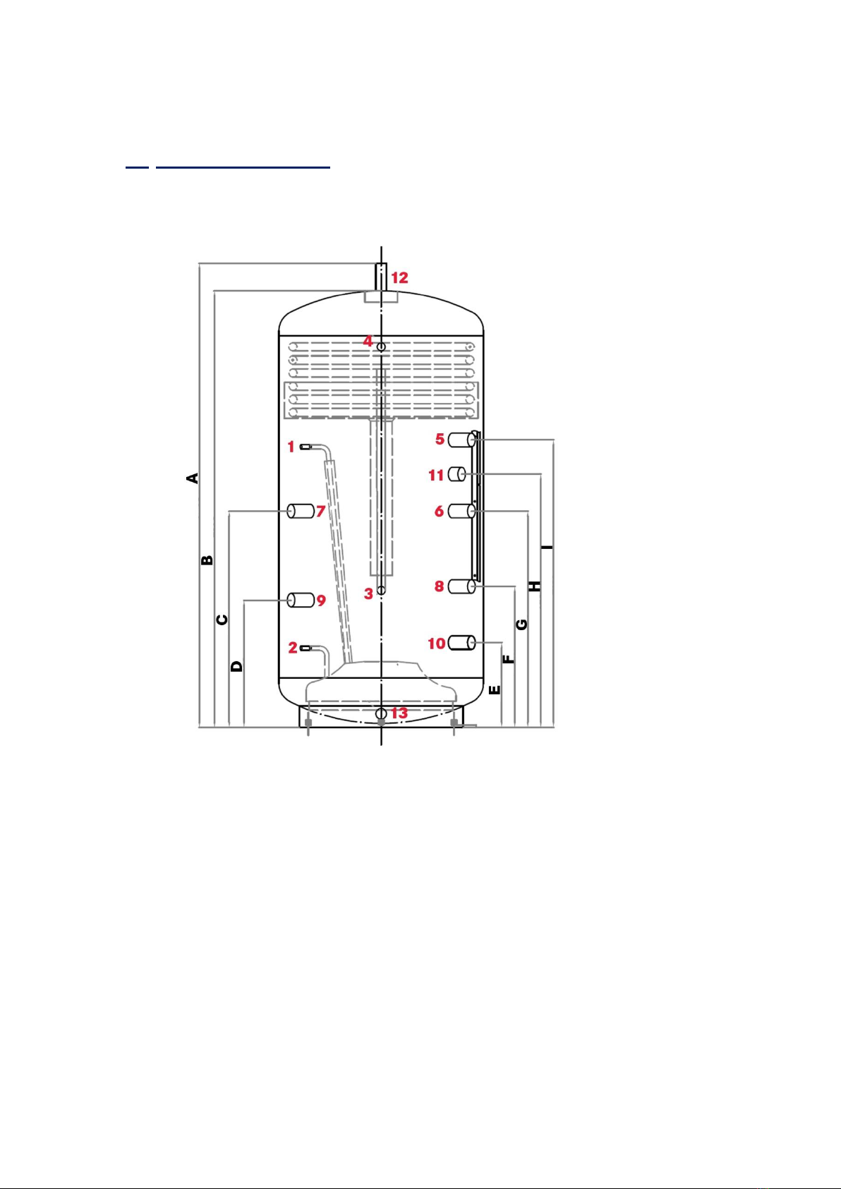
3.3. Vent valve
Assemble a manual vent valve at the vent nozzle (12)

Pagina 4 ǀ8
InstAnl.V08-2014-0
3.4. Water connection and safety group
Perform all connecting and installing work according to the valid rules and regulations. Take
assembling hints of the safety group into account.
Flush all pipes connected to the storage tank.
Assemble the hot water pipe and the cold water pipe as well as the safety group to the cold
water supply line. Thereby pay attention to the resting pressure of the chilled water
distribution net and use a pressure reducing valve if necessary.
3.5. Temperature sensor
Position the sensor at the height of the terminal strip, at which the temperature for the control
function should be recorded.
4. Start-up
Before start-up the system has to be tested for leaks, the right hydraulic connection as well
as correct electrical connections. Furthermore an attentive, respectively an appropriate
rinsing of the system in accordance with DIN 4753 has to be carried out.
Open a followed tapping point until the device is filled and the pipeline system is free from air.
Fill and air the heating system as well as the heat exchanger.
Control the function of the safety valve as well as further security-related
supplies.
Control the accessories.

Pagina 5 ǀ8
InstAnl.V08-2014-0
5. Technical Data
5.1. Measures and connectors
Recommended terminal assignment:
1 2Power flow pipe
2 2Power return flow
3 Cold water supply line
4 Hot water outlet
5 Heat generator flow pipe
6 Heat generator return flow
7 Flow pipe heat generator 1/ heating flow pipe
8 Return flow heat generator 2/ heating return flow
9 Flow pipe heat generator 2
10 Return flow heat generator 2
11 Auxiliary electric heating
12 Vent
13 Drain

Pagina 6 ǀ8
InstAnl.V08-2014-0
Storage dimensions in mm:
A
B
C
D
E
F
G
H
I
J
2P 400l
1,406
1,306
590
350
260
400
590
725
850
650
2P 600l
1,695
1,595
790
465
310
515
790
925
1,050
750
2P 850l
1,885
1,785
785
465
350
615
945
1,080
1,205
800
2P 1000l
1,885
1,785
785
465
350
615
945
1,080
1,205
850

Pagina7 ǀ8
InstAnl.V08-2014-0
5.2. Technical data
400 liter
600 liter
850 liter
1000 liter
Content:
Heating water
400l
618l
805l
921l
Drinking water
14l
24l
36l
36l
Material
Stainless
steel
Stainless
steel
Stainless
steel
Stainless
steel
Solar heat exchanger:
0.8l
0.8l
1.9l
1.9l
Material
Copper
Copper
Copper
Copper
Screw connection
15mm
15mm
18mm
18mm
Dimensions:
Height
1406mm
1695mm
1885mm
1885mm
Tilted dimension
1550mm
1855mm
2050mm
2070mm
Diameter
(without insulation)
650mm
750mm
800mm
850mm
Empty weight:
125kg
165kg
185kg
200kg
Surface:
Solar heat exchanger
Drinking water heat exchanger
2m²
2.5m²
2m²
4m²
3.1m²
6m²
3.1m²
6m²
Continuous output
Storage temperature = 70°C approx.:
15kW
25kW
35kW
6.5l/min
9.5l/min
15l/min
7.5l/min
13l/min
18l/min
9l/min
15l/min
21l/min
9l/min
15l/min
21l/min
Draw off rate limitation:
Storage temperature = 70°C
Storage temperature = 55°C
15l/min
11l/min
21l/min
15l/min
31l/min
22l/min
31l/min
22l/min
Pressure drop drinking water
approx.:
at 20l/min
0.08 bar
0.11 bar
0.17 bar
0.17 bar
Specific volume flow
per 2Power-unit:
Solar heat exchanger
50l/h
50l/h
50l/h
50l/h

Page 8 ǀ8
InstAnl.V08-2014-0
6. Disposal
When disposing a 2Power system the applicable local rules and regulations of the appropriate
disposal area must be observed at the time of disposal.
Agiba Heating disclaims any and all responsibility for units damaged after having been operated together with 2Power
modules supplied by Agiba Heating but failing to take heed of technical data sheets and the installation instructions Subject
to technical modifications in the course of product advancement. Mistakes and errors reserved.
Agiba Heating
Frjentsjerterdyk 1
8855 XC Sexbierum
www.agibaheating.nl
Tel.: +31 (0)72 7920174
agibaheating.nl
This manual suits for next models
3
Table of contents
Popular Water Heater manuals by other brands

PrecisionTemp
PrecisionTemp cIAPMO-T RV-550-EC manual

Rheem
Rheem RUUD Gas Hot Water Supply Heaters Specification sheet

Grant
Grant DuoWave Plus System Installation & user's instructions

STIEBEL ELTRON
STIEBEL ELTRON SN 5 SLI comfort Operation and installation

Noritz
Noritz NCC199-SV installation manual

Thermann
Thermann TIHP300 owner's manual

Modena
Modena ES Series manual

Kenmore
Kenmore 153.313340 owner's manual

Heatrea Sadia
Heatrea Sadia PremierPlus SystemFit Installation and user manual

SmarTherm
SmarTherm 10L 2kw USHW Instructions for use

Maxwell
Maxwell MSxxxC2T series Installation and instruction manual

Elkay
Elkay EFHA8 installation instructions