3C Concept TC-SPLIT User manual

TC-SPLIT USER MANUAL
1
3C Concept S.A.S 1 TC-SPLIT_MANUEL_EN_105.DOCX
TC-SPLIT
One product, multiple features:
•Signal converter: adapt encoder output voltage levels to devices inputs
(PLC, variable frequency drive …)
•Unipolar / differential converter
•Splitter: send encoder signals to multiples devices (4 outputs per
module, unlimited numbers of chained devices)
•Insulator: galvanic isolation between encoder and module outputs, and
between module outputs themselves.
•Multiplexer: Choice of the source encoder signal (using two chained
modules at least)
PDF Manual PDF available at: www.3cconcept.fr/tcusb

TC-SPLIT USER MANUAL
2
3C Concept S.A.S 2 TC-SPLIT_MANUEL_EN_105.DOCX
1 –Overview
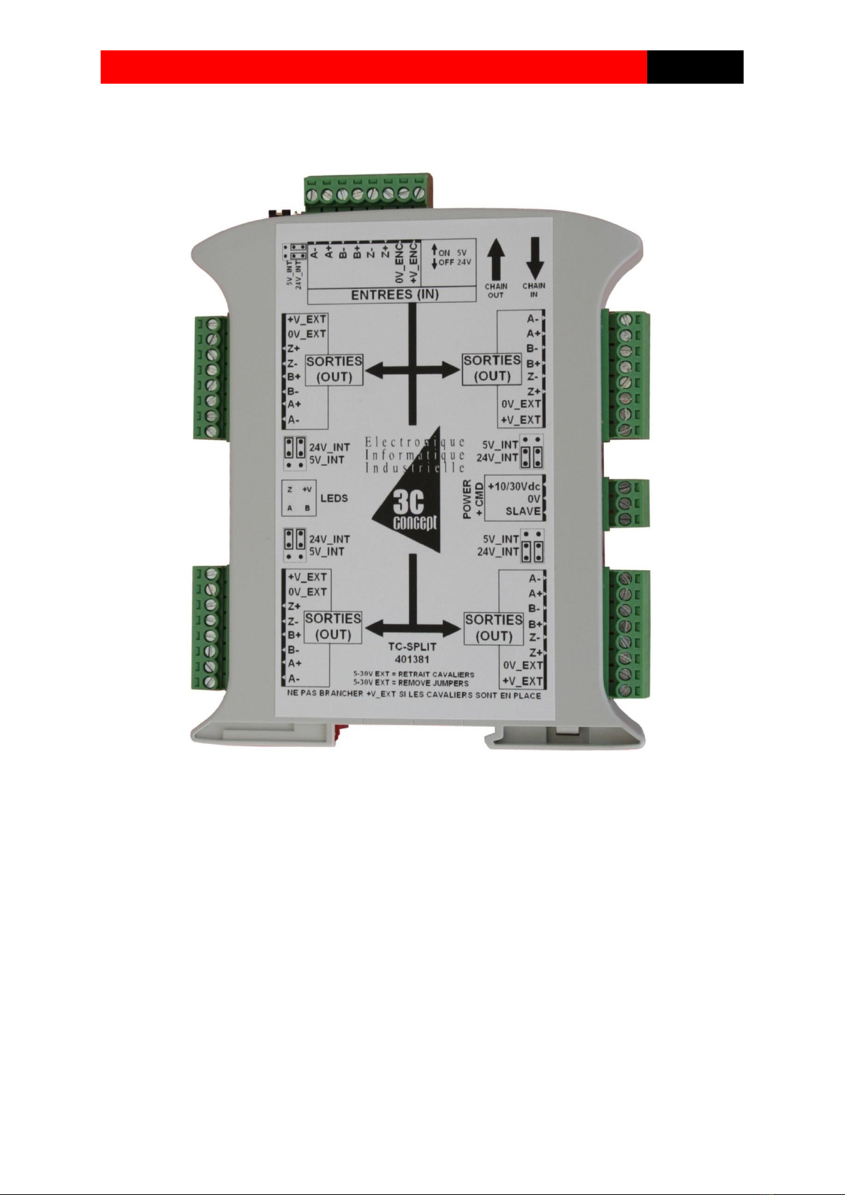
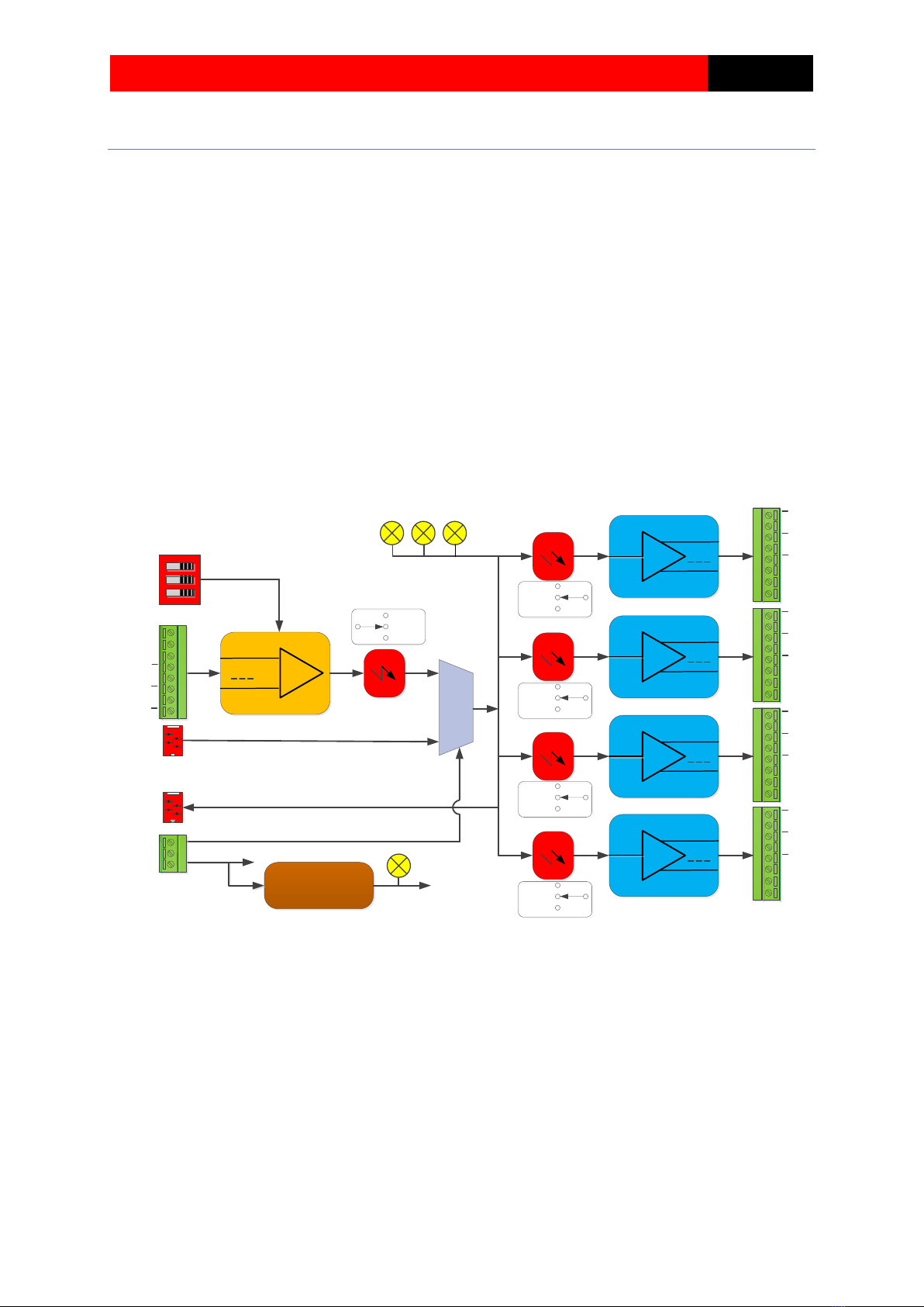
TC-SPLIT Module allows connection of 4 devices on the same incremental encoder (or similar
devices). It can be chained in order to obtain 8,12,16 outputs.
3 independent channels (A,B,Z) are available on each device output
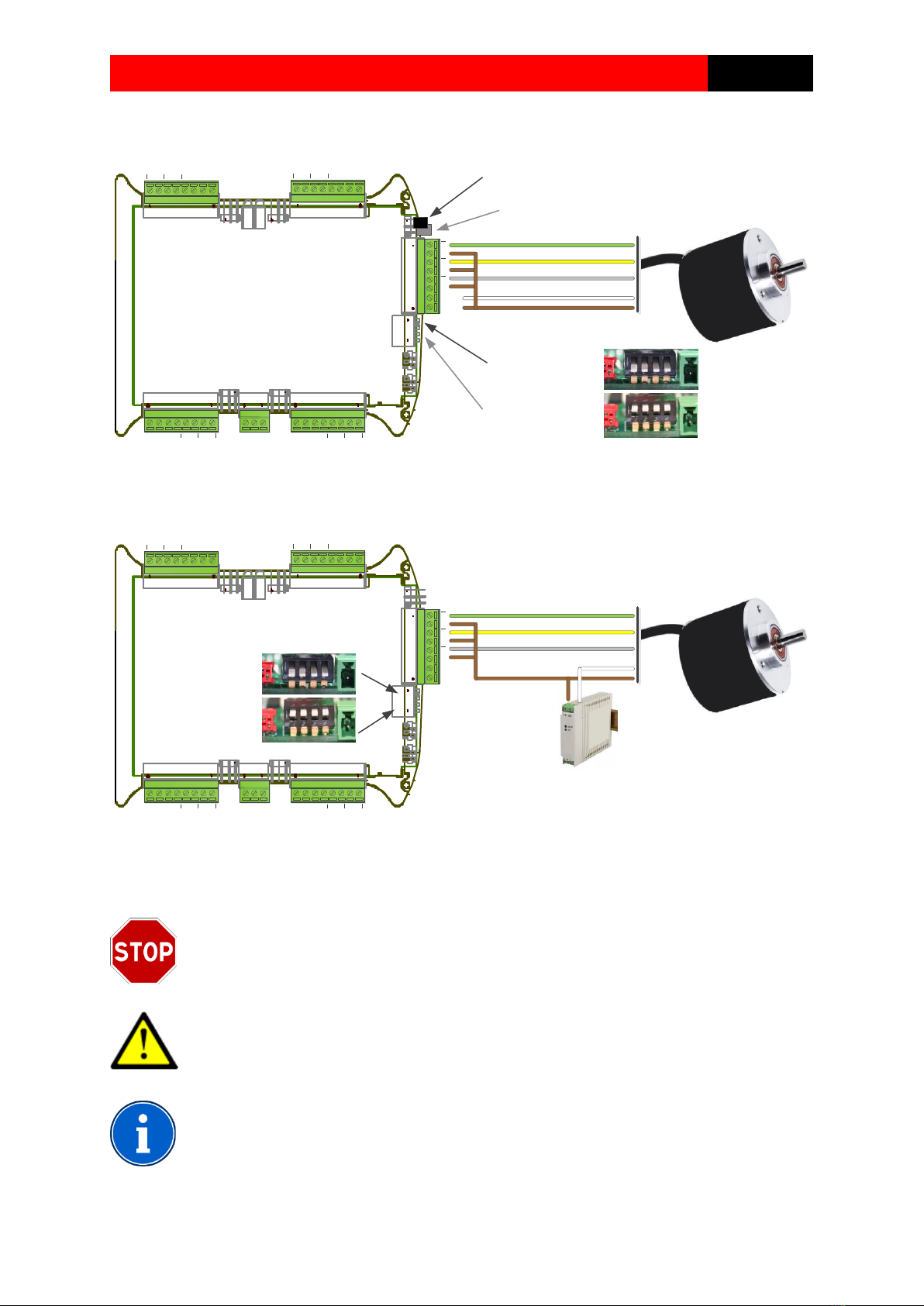
Encoder input signals can be configured as RS422/TTL/HTL unipolar or differential.
Each group of (input or output) module can be galvanic isolated, if an external power is provided
High working frequency (greater than usual encoder working frequency)
TC-SPLIT Module can be mounted on DIN Rail
Module is powered by a DC source voltage, between 10 to 30V. Typical power is less than 0.5W
(without encoder or loads)
A, B, Z
A, B, Z
A, B, ZA, B, Z
A, B, Z
INT-24V
EXT (ISO)
INT-5V
A
B
Z
A
Z
B
0V_EXT
+V_EXT
A, B, ZA, B, Z
A, B, Z
INT-24V
EXT (ISO)
INT-5V
A
B
Z
A
Z
B
0V_EXT
+V_EXT
A, B, ZA, B, Z
A, B, Z
INT-24V
EXT (ISO)
INT-5V
A
B
Z
A
Z
B
0V_EXT
+V_EXT
A, B, ZA, B, Z
A, B, Z
INT-24V
EXT (ISO)
INT-5V
A
B
Z
A
Z
B
0V_EXT
+V_EXT
INT-24V
EXT (ISO)
INT-5V
1
1
1
1
1
A
B
Z
A
Z
B
0V_ENC
+V_ENC
+10/30V 1
0V
SLAVE
MASTER ->
SLAVE <-
5V / 24V
INPUTS
SOURCE
A B Z
Power supply INT-5V
P1
P2
P3
P4
P5
P6
P7
P8
INT-24V
LEDS
POWER LED
ISOLATION
ISOLATION

TC-SPLIT USER MANUAL
3
3C Concept S.A.S 3 TC-SPLIT_MANUEL_EN_105.DOCX
2 –Technical Characteristics
Parameter
Type
Pinout
Value
Unit
Power
Module
P3.1
10 à 30
VDC
V_EXT
Pn.8
4.5 à 30
VDC
Max supply current
P3.1
250
mA
Supply current @24V (1)
P3.1
50
mA
Max supply current, 5V (+V_ENC)
P1.8
200
mA
supply current V_EXT (1)
Pn.8
25
mA
Counting
Max Frequency (differential)
A/B/Z
1000
KHz
Max Frequency (unipolar)
A/B/Z
250
KHz
Max propagation time
A/B/Z
1
µs
Inputs (5V)
(input switch ON)
Input impedance
P1 (1-6)
700
Ohms
Nominal input current
P1 (1-6)
5
mA
Min. voltage for NL1 (2)
P1 (1-6)
2.6
V
Max voltage for NL0 (2)
P1 (1-6)
1.5
V
Max allowed voltage
P1 (1-6)
8.0
V
Inputs (24V)
(Input switch OFF)
Input impedance
P1 (1-6)
4000
Ohms
Nominal input current
P1 (1-6)
5
mA
Min. voltage for NL1 (2)
P1 (1-6)
10
V
Max voltage for NL0 (2)
P1 (1-6)
5
V
Max allowed voltage
P1 (1-6)
30
V
Output (5V)
(INT or EXT Power)
Max output current
Pn (1-6)
25
mA
Min. voltage for NL1 (3)
Pn (1-6)
3.0
V
Max voltage for NL0 (3)
Pn (1-6)
0.8
V
Output (24V)
(INT or EXT Power)
Max output current
Pn (1-6)
25
mA
Min. voltage for NL1 (4)
Pn (1-6)
21
V
Max voltage for NL0 (4)
Pn (1-6)
0.8
V
Others
Size
130x101x18
mm
Protection rating
IP20
Operating temperature (5)
-20/+60
°C
Notes:
(1) No load on A/B/Z outputs, no encoder powered
(2) NL1: Logic level 1 (active), NL0: Logic level 0 (inactive)
(3) On 5mA load
(4) On 10mA load, supposing 24Vdc power, if not Vo= Vpower -3V
(5) No condensing
Use shielded multipair cables.
Each pair must be affected to a signal and its complement (example: A+, A-). Cable
shielding should be tied to earth on the electric box. As a good practice, you should
separate power cable from instrumentation signals. Power cable cross-section should
be of sufficient size if module is powered by 5Vdc (avoid this if distance is superior
greater than 5 meters)

TC-SPLIT USER MANUAL
4
3C Concept S.A.S 4 TC-SPLIT_MANUEL_EN_105.DOCX
3 - Configuration and encoder cabling (P1)
3.1 –Differential encoder (RS422 or HTL differential outputs), not isolated
A
B
Z
A
Z
B
0V_EXT
+V_EXT
1
A
B
Z
A
Z
B
0V_EXT
+V_EXT
1
A
B
Z
A
Z
B
0V_EXT
+V_EXT
1
A
B
Z
A
Z
B
0V_EXT
+V_EXT
1
A
B
Z
A
Z
B
0V_EXT
+V_EXT
1
+10/30V
1
0V
SLAVE
Jumper pos. for powering
encoder with 5Vdc
Jumper pos. for powering
encoder with 24Vdc Encoder or signals
source
Encoder ouput level: 5V/TTL
switch in low pos. (ON)
Encoder ouput level: 10-30Vdc
switch in high pos.(OFF)
3.2 - Differential encoder (RS422 or HTL differential outputs), isolated
A
B
Z
A
Z
B
0V_EXT
+V_EXT
1
A
B
Z
A
Z
B
0V_EXT
+V_EXT
1
A
B
Z
A
Z
B
0V_EXT
+V_EXT
1
A
B
Z
A
Z
B
0V_EXT
+V_EXT
1
A
B
Z
A
Z
B
0V_EXT
+V_EXT
1
+10/30V
1
0V
SLAVE
Encoder or signals
source
Encoder ouput level: 5V/TTL
switch in low pos. (ON)
Encoder ouput level: 10-30Vdc
switch in high pos.(OFF)
External power: NO jumpers
Outputs are isolated
Encoder power supply
See notes and usage precaution on next page.

TC-SPLIT USER MANUAL
5
3C Concept S.A.S 5 TC-SPLIT_MANUEL_EN_105.DOCX
3.3 –Unipolar encoder (open collector or unipolar TTL/HTL outputs), not isolated
A
B
Z
A
Z
B
0V_EXT
+V_EXT
1
A
B
Z
A
Z
B
0V_EXT
+V_EXT
1
A
B
Z
A
Z
B
0V_EXT
+V_EXT
1
A
B
Z
A
Z
B
0V_EXT
+V_EXT
1
A
B
Z
A
Z
B
0V_EXT
+V_EXT
1
+10/30V
1
0V
SLAVE
Jumper pos. for powering
encoder with 5Vdc
Jumper pos. for powering
encoder with 24Vdc Encoder or signals
source
Encoder ouput level: 5V/TTL
switch in low pos. (ON)
Encoder ouput level: 10-30Vdc
switch in high pos.(OFF)
3.4 –Unipolar encoder (open collector or unipolar TTL/HTL outputs), isolated
A
B
Z
A
Z
B
0V_EXT
+V_EXT
1
A
B
Z
A
Z
B
0V_EXT
+V_EXT
1
A
B
Z
A
Z
B
0V_EXT
+V_EXT
1
A
B
Z
A
Z
B
0V_EXT
+V_EXT
1
A
B
Z
A
Z
B
0V_EXT
+V_EXT
1
+10/30V
1
0V
SLAVE
Encoder or signals
source
Encoder ouput level: 5V/TTL
switch in low pos. (ON)
Encoder ouput level: 10-30Vdc
switch in high pos.(OFF)
+V
Encoder power supply
Unipolar wiring must not be used with long cabling distance or within high electromagnetic
environments.
Input voltage must not be greater than 8V if switches are in low position
Never set jumpers vertically
Never set external power on [P1.7; P1.8] if jumpers are populated
Wiring colours used above are not standardized, double check datasheet of the
encoder for correct wiring
After module power up, it is possible to check the operation by slowly moving the
encoder axis, the 3 leds on the side of the TC-SPLIT should blink.

TC-SPLIT USER MANUAL
6
3C Concept S.A.S 6 TC-SPLIT_MANUEL_EN_105.DOCX
4 - Configuration and module outputs cabling (P5 P6 P7 P8)
4.1 –Differentials outputs (RS422 or HTL differential)
Examples with and without power supply from external device
A
B
Z
A
Z
B
0V_EXT
+V_EXT
1
A
B
Z
A
Z
B
0V_EXT
+V_EXT
1
A
B
Z
A
Z
B
0V_EXT
+V_EXT
1
A
B
Z
A
Z
B
0V_EXT
+V_EXT
1
A
B
Z
A
Z
B
0V_EXT
+V_EXT
1
+10/30V
1
0V
SLAVE
External power from VFD: NO jumpers,
Output are isolated
Variable-frequency drive(VFD)
with differentials inputs and
power output (5 to 30Vdc)
Internal power: SET Jumpers as decribed,
Output are not isolated
5V Outputs
24V Outputs
Optional 0V wire
Variable-frequency
drive(VFD) with
differentials inputs but
no power output
24V
5V
24V
5V
Outputs isolation
Kind of power supply
1-2
(right)
2-3
(left)
Not isolated
5VdcInternal power supply
YES
-
10-30Vdc Internal power supply
-
YES
Isolated
5-30Vdc External power supply
-
-
« YES »: mean that 2 Jumpers must be set superimposed horizontally
Pin 1 of the jumpers is at the right of the connector (assuming terminal screw on the top)
Jumpers on the left (10-30V) LEDS Jumpers on the right (5V)

TC-SPLIT USER MANUAL
7
3C Concept S.A.S 7 TC-SPLIT_MANUEL_EN_105.DOCX
Example with power supply separated from the main device (isolated output)
A
B
Z
A
Z
B
0V_EXT
+V_EXT
1
A
B
Z
A
Z
B
0V_EXT
+V_EXT
1
A
B
Z
A
Z
B
0V_EXT
+V_EXT
1
A
B
Z
A
Z
B
0V_EXT
+V_EXT
1
A
B
Z
A
Z
B
0V_EXT
+V_EXT
1
+10/30V
1
0V
SLAVE
External power from PLC:
NO jumpers
Outputs are isolated
Programmable logic
controller with
differentials inputs
External independent
power supply
(12 or 24Vdc)
Never set Jumpers vertically (risk of destruction)
On RS422 devices (5v max), you have to match impedance line by adding 120 Ohms
resistors at each line termination:

TC-SPLIT USER MANUAL
8
3C Concept S.A.S 8 TC-SPLIT_MANUEL_EN_105.DOCX
4.2 –Unipolar outputs (TTL 5V or HTL 10-30V outputs)
A
B
Z
A
Z
B
0V_EXT
+V_EXT
1
A
B
Z
A
Z
B
0V_EXT
+V_EXT
1
A
B
Z
A
Z
B
0V_EXT
+V_EXT
1
A
B
Z
A
Z
B
0V_EXT
+V_EXT
1
A
B
Z
A
Z
B
0V_EXT
+V_EXT
1
+10/30V
1
0V
SLAVE
External power from VFD: NO jumpers,
Output are isolated
Variable-frequency
drive(VFD) with unipolar
inputs and power
output (5 to 30Vdc)
Internal power: SET Jumpers as decribed,
Output are not isolated
5V Outputs
24V Outputs
Optional 0V wire
Variable-frequency drive(VFD)
with unipolar inputs but no
power output
Outputs isolation
Kind of power supply
1-2
(right)
2-3
(left)
Not isolated
5VdcInternal power supply
YES
-
10-30Vdc Internal power supply
-
YES
Isolated
5-30 Vdc External power supply
-
-
« « YES »: mean that 2 Jumpers must be set superimposed horizontally
Pin 1 of the jumpers is at the right of the connector (assuming terminal screw on the top)
In isolated mode, output voltage level on A/B/Z is almost identical of the power supply voltage level
(see characteristics, page 3)
Jumpers on the left (10-30V) LEDS Jumpers on the right (5V)

TC-SPLIT USER MANUAL
9
3C Concept S.A.S 9 TC-SPLIT_MANUEL_EN_105.DOCX
5 –Module power supply and multiplexer input (P3)
5.1 - Wiring
A
B
Z
A
Z
B
0V_EXT
+V_EXT
1
A
B
Z
A
Z
B
0V_EXT
+V_EXT
1
A
B
Z
A
Z
B
0V_EXT
+V_EXT
1
A
B
Z
A
Z
B
0V_EXT
+V_EXT
1
A
B
Z
A
Z
B
0V_EXT
+V_EXT
1
+10/30V
1
0V
SLAVE
Regulated power supply
(12 or 24Vdc)
Optional switch
Opened= use internal source
Closed= external source
From master moduleTo slave module
Mode
Outputs
Slave
Input
Standalone (Master)
TC-SPLIT outputs are sourced from
TC-SPLIT main input (P1)
-
Chained (Slave)
TC-SPLIT outputs are sourced from
Chain IN input (which comes from a
master module, Chain OUT)
> 10V
SLAVE input must be left floating if TC-SPLIT is used in the standalone mode
5.2 –LEDS identification

TC-SPLIT USER MANUAL
10
3C Concept S.A.S 10 TC-SPLIT_MANUEL_EN_105.DOCX
Notes:

TC-SPLIT USER MANUAL
11
3C Concept S.A.S 11 TC-SPLIT_MANUEL_EN_105.DOCX
Notes :

TC-SPLIT USER MANUAL
12
3C Concept S.A.S 12 TC-SPLIT_MANUEL_EN_105.DOCX
Table of contents
Popular Media Converter manuals by other brands

Converters.TV
Converters.TV 15155 Operation manual

Leine Linde
Leine Linde 901 Mounting instructions

Analog way
Analog way QuickMatriX QMX150 user manual

Speaka Professional
Speaka Professional 2615378 operating instructions

Bosch
Bosch VIP-X1600-XFM4A Quick installation guide

Transition Networks
Transition Networks C/E-100BTX-FX-05(LH) user guide