3D R DIY QUAD Manual

1
DIY QUAD
Build Manual
V.A
2014

2
Thanks for purchasing a DIY Quad!
These instructions will show you how to assemble a Quad using the Pixhawk
autopilot system and ArduCopter/APM:Copter firmware. If you plan to use
other components in your build, please adjust these instructions accordingly.
For online instructions, visit 3dr.com/diy-quad-kit.
Frame parts 3
Electronics 4
Tools 4
1 Motor assembly 5
2 Power system wiring 8
3 Body plate assembly 10
4 Pixhawk assembly 15
5 Leg assembly 21
6 Calibration 22
7 Propeller assembly 22
Contents

3
Frame parts
30 mm bolts (6)
25 mm bolts (30)
5 mm bolts (32)
nylon bolts (4)
30 mm male-female standos (4)
19 mm hollow spacers (20)
18 mm female-female standos (12)
base plate
top plate
Pixhawk plate
accessory plate
metal nuts (42)
nylon nuts (4)
thumb nuts (2)
leg plates (8)
leg support plates (4)
motor plates (8)
velcro strips (one pair)
velcro straps (3)
dual lock
15 cm four-wire cable
15 cm female-female servo cable
30 cm male-female servo cable
15 cm six-wire cable
zip ties
blue arms (2)
black arms (2)
power distribution board
threadlocker

4
Electronics
To complete this build, you will need the following tools not included with your kit:
• Phillips screwdriver
• Double-side foam tape or other mounting adhesive
• Soldering equipment
Note: The electronics for this build require soldering. If you’re unfamiliar with soldering,
our friends at Sparkfun have some great tutorials that can get you started, including this
comic. For an example of exactly what soldering you’ll be doing in this build, view this
video tutorial.
Tools
This build uses the Pixhawk autopilot
system, including these components:
• Pixhawk autopilot
• u-blox GPS with Compass
• Telemetry radios
• Radio control system
• ArduCopter/APM:Copter firmware
Click here for more information
about these components and to view
compatible radio control systems.

5
1Motor
assembly
Follow these instructions to assemble
one motor.
1 Attach motor to arm
Place a motor plate on top of the arm
with the short end of the plate facing
towards the end of the arm. Place the
motor on top of the plate, and align
the two small holes in the motor,
plate, and arm. Orient the motor with
the cables as close as possible to the
hole in the side of the arm.
Apply threadlocker to two 5 mm
bolts, and secure the motor and plate
to the arm from below by accessing
through the two large holes in the
bottom of the arm. When applying
threadlocker, use less than one drop,
and cover only four or five threads
where the bolt connects with the
motor. Make sure to insert the bolts
into the holes in the bottom of the
motor and not into the slots where
they could interfere with the motor.

6
2 Thread motor cables through arm
Thread the motor cables through the
hole in the side of the arm.
3 Attach bottom plate to arm
Place a motor plate against the
bottom of the arm with the short end
of the plate facing towards the end
of the arm. Apply threadlocker to the
ends of three 25 mm bolts (less than
one drop covering four or five threads
at the end of the bolt). Place a 19 mm
hollow spacer between each of the
pairs of holes in the two motor plates.
Place the bolt through the motor
plates and spacer, and secure from
below with a metal nut.
Repeat these instructions for all
motors.

7
2Power system
wiring
Follow these instructions to connect
the power system.
1 Solder Deans to ESCs
Solder a Deans connector to the red
and black wires on each electronic
speed controller (ESC). Check the
Deans connectors for the + and –
markings, and solder the + side to
the red wire and the – side to the
black wire. Don’t forget to add heat
shrink tubing to the wires before
soldering, and shrink the tubing over
the finished connections.
2 Number ESCs
Use tape (or other method) to label
each ESC with a number one through
four.
Deans to ESC:
negative = black
positive = red
-+

8
3 Connect ESCs to PDB
Connect the Deans connectors
(red) on the ESCs to the Deans
connectors on the power distribution
board (PDB) in any order.
Take a look at the PDB and find the
pins labelled M1 through M4
(motors 1 through 4), and make a
note of which color wire connects to
each. Now connect the three-wire
cables from each ESC to these pins
on the PDB according to the ESC
numbers. This is where the order is
critical. Connect the ESC that you
labelled as “1” to the pins on the PDB
labelled “M1”, ESC 2 to PDB pins M2,
ESC 3 to PDB pins M3, and ESC 4 to
PDB pins M4. Connect the white wire
to the signal pin (labelled “M1”), the
red wire to the power pin (labelled
“+”), and the black wire to the ground
pin (labelled “-”).
4 Connect PDB to power module
Attach the XT60 connector (yellow)
on the PDB to the XT60 connector on
the power module.

9
3Body plate
assembly
Follow these instructions to assemble
the body plates.
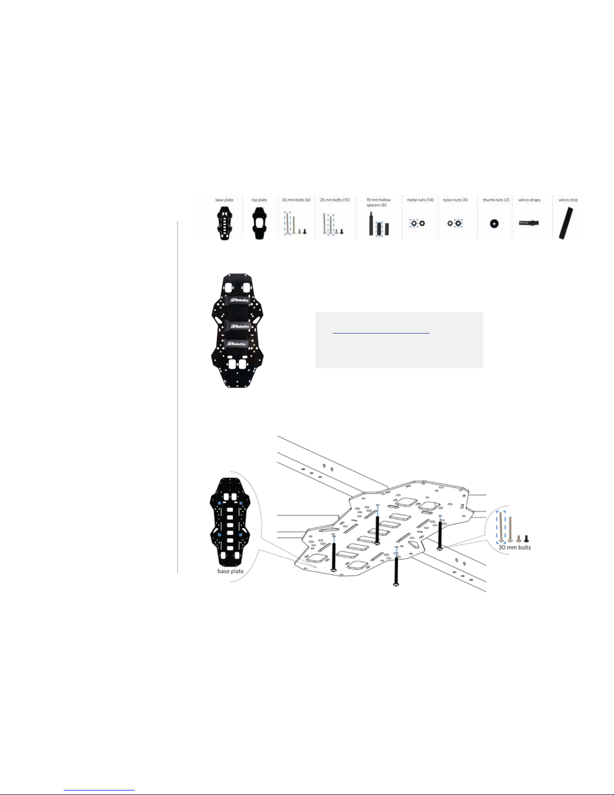
1 Add velcro straps to base plate
Thread the two velcro straps through
the slots in the base plate. These
straps will hold the battery to the
bottom of your copter. The perfectly
flat side of the plate (without the
protruding nuts) should face down.
Your kit includes two velcro strips to
attach to the battery and the bottom
of the copter. To install, attach the
strip with loops (fuzzy) to the bottom
of the plate between the straps, and
attach the strip with hooks (smooth)
to your battery.
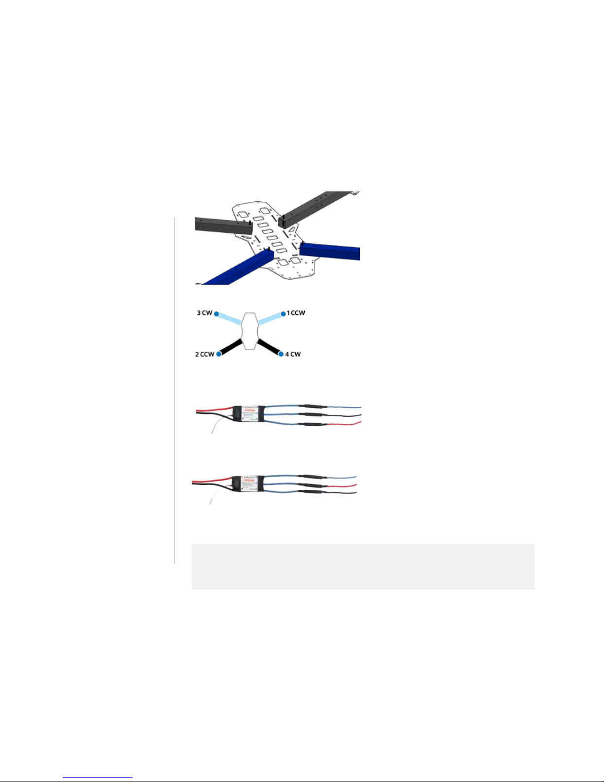
2 Attach arms to base plate
Now we’ll attach the four arms with
assembled motors to the base plate.
Using the innermost hole in the arm
and the hole in the base plate marked
below, insert a 30 mm screw from
the bottom, up through the plate and
the arm. Attach the two black arms
and two blue arms as shown in
relation to the shape of the plate.
(Attach the black arms to the more
elongated end of the plate.)
Visit the APM:Copter Wiki and learn
more about which batteries to use
with your copter.

10
It may be helpful to secure each arm
in place temporarily with a metal nut.
3 Label motors
Use tape (or other method) to label
the motors by the numbers shown
here.
4 Connect ESC and motor cables
Connect the motor cables to the
corresponding ESC cables according
to the labelled numbers (connect
motor 1 to ESC 1, motor 2 to ESC 2,
etc). The order of the three cables
determines which direction the
motors will spin and is critical for the
copter to fly correctly. The diagram
above shows which motors need to
spin clockwise (CW) and counter-
clockwise (CCW).
The images below show the correct wiring to produce each direction of rotation. The motor
cables are dierentiated by color. To dierentiate the ESC cables, orient the ESC with the
label facing up, and use the relation of the cables to the label.
top = blue
center = red
bottom = black
COUNTERCLOCKWISE (CCW) ROTATION WIRING
top = blue
center = black
bottom = red
CLOCKWISE (CW) ROTATION WIRING
Other manuals for DIY QUAD
1
Table of contents


