3nStar PTE0912 User manual

Copyright
This document is copyrighted, © 2022. All rights are reserved. No part of this document
may be reproduced, copied, translated, or transmitted in any form or by any means without the
prior written permission from 3nStar Inc. Information provided in this manual is intended to be
accurate and reliable. However, 3nStar Inc. assumes no responsibility for its use, nor for any
infringements upon the rights of third parties, which may result from its use.
The material in this document is for product information only and is subject to change
without notice. While reasonable efforts have been made in the preparation of this document
to assure its accuracy, 3nStar Inc., assumes no liabilities resulting from errors or omissions in
this document, or the use of the information contained herein.

Table of Contents
1. Introduction
Quick Start Guide 004 - 004
Introduction 005 - 006
Terminology & Tools 006 - 008
Dimensions 008 - 009
Specification 009 - 010
2. Assembly
Single Hinge Stand 011 - 013
Add-on Devices 014 - 015
3. Software Installation & Setup
Chipset 015 - 016
Audio 017 - 017
Graphics 018 - 018
Intel ME 019 - 019
Serial IO 020 - 021
LAN 021 - 021
Sensor Driver 021 - 022
Cash Drawer Address 022 - 022
BIOS Introduction 023 - 024
4. Key Component Access
Access Memory 024 - 025
Adding or Removing M.2 PCBA from M.2 Tray 026 - 027

4
Quick Start Guide

5
Introduction
PTE0912 is a 15inch panel pc based on Intel’s 12th generation Alder Lake CPU.

6
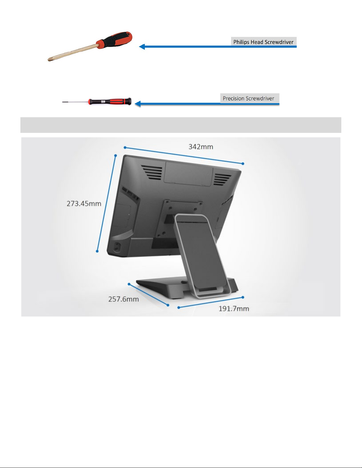
Terminology and Tools
Smart DD: This is a proprietary port that can support two Smart DD monitors daisy chaining. This port utilizes a USB-C
connector but it is NOT compatible with previous generation USB-C (USB DP) ports. Contact your sales represenative for
additional information.
Smart DP: This is a proprietary port used only for Smart DP displays such as XM-3010W Smart DP SKU. Previous
generation displays titled Smart DP can be used on the Smart DP port, however there will be a exclamation error in the
Control Panel that cannot be corrected. This will not affect the use of the Smart DP display.
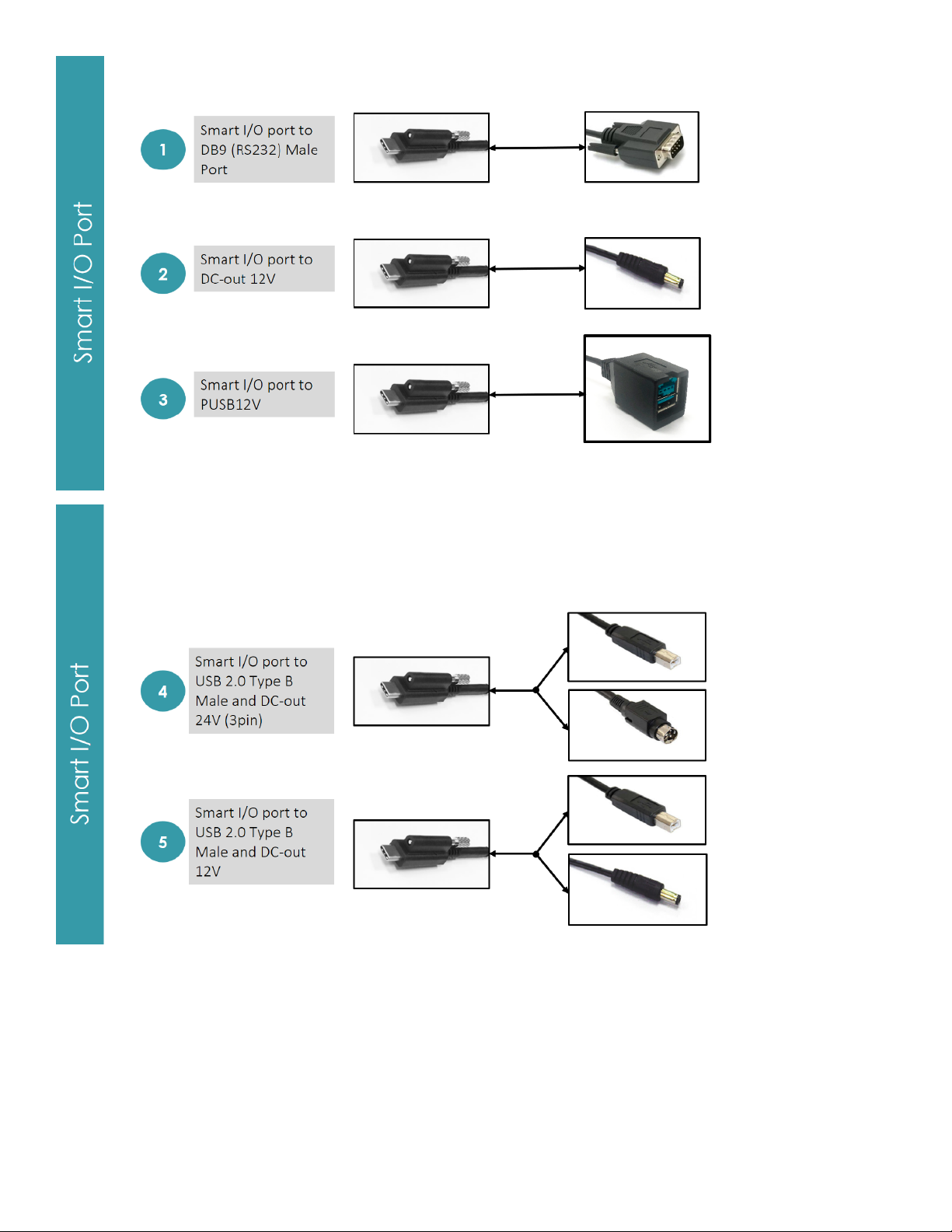
Smart I/O: This is a proprietary port that can support multiple expansion I/O cables. Toggling of related power is set in the
BIOS under Advanced > Product Setting. The default power setting in the BIOS is set to the lowest choice. For example,
the dafualt power for the RJ45 to DB9 is set to RI.
Universal I/O (UIO): This is a optional port that can be selected by the customer. Available ports on this system includes
(Maximum 1 selection per system):
①PUSB24V, ②PUSB12V, ③RJ45 (RS232) RI/5V/12V, ④USB 2.0 Type A (Dual Stack)

7
Some of these tools may be used for the assembly.

8
Dimensions

9
Specification
Note: This model does not support VPro or iAMT. Contact your 3nStar sales representative for other qualifying products.

10

11
Assembly
Single Hinge Stand
Note: This is a general reference assembly guide, the actual display back cover may not match your product. It will not
matter to the assembly.
Tools Needed: You will need to prepare a screwdriver in order to assemble the stand.
Items Included:
Panel PC with Part A of the stand attached.
Part B of the stand
Screw x 4pcs in the accesory box.
STEP 1: Lay items on a flat surface.

12
STEP 2: Remove the stand cable cover by sliding it down (left image) then lift it away (right image).
STEP 3: Lift up the angle of Part A of the stand.
STEP 4: Align Part B of the base with Part A of the base as shown. While holding the base together with one hand. Use
your hand to slightly fasten the screws . Then use the screwdriver to tightly fasten it.

13
STEP 5: Place the stand in the upright position (left image) then use the screwdriver to fasten the two screws (right
image).
STEP 6: Place the stand cable cover back on the stand. Then assembly is complete.

14
Add-on Device
Note: This is a general reference assembly guide, the actual display back cover may not match your product. It will not
matter to the assembly.
Tools Needed: You will need to prepare a screwdriver in order to assemble the add-on device.
Items Included:
Panel PC with Part A of the stand attached.
Part B of the stand
Screw x 4pcs in the accesory box.
STEP 1: Remove the side cover.
STEP 2: Connect the add-on device to the system.

15
STEP 3: Fasten the two screws. Complete.
Software Installation and Setup
For the most up to date drivers, go to https://www.3nStar.com
Follow the below order if installation for the Motherboard:
①Chipset ②Audio ③Graphics ④Intel® ME
⑤Setup Serial IO ⑥LAN ⑦Sensor
1. Chipset
•Locate chipset folder and double click on [ SetupChipset ]
•Click [ Next ]
•Click [ Accept ]

16
•Click [ Install ]
•Click [ Yes ]
•Click [ Restart Now ]

17
2. Audio
•Double click [ Setup ]
•Click [ Yes ]
•Click
[ Next ]
•
Click
[ Yes, I want to restart my computer
now ], [ Finish ]

18
3. Graphics
•Double Click [ Installer.exe ]
•Click [ Yes ]
•Click [ Next ]
•Click [ Next ]
•Click [ Finish ]

19
4. Intel® ME
•Double Click [ DPInst64.exe]
•Click [ Next ]
•Accept Terms then click [ Next ]
•Click [ Next ]
•Click [ Yes ]
•Click [ Finish ]

20
5. Serial IO
•Double Click [ SetupSerialIO.exe ]
•Click [ Next ]
•Accept terms then click [ Next ]
•Click [ Next ]
•Click [ Next ]
•Select Yes, I want to restart this
computer now the click [ Finish ]
This manual suits for next models
1
Table of contents
Popular Touch Panel manuals by other brands

Pro DVX
Pro DVX APPC-15XP-R23 quick start guide

Heal-Tech
Heal-Tech GIpro DS Series Installation and operation manual

Saia Burgess Controls
Saia Burgess Controls PCD7.D6120TV010 Hardware manual

Winmate
Winmate GC Series user manual

IEI Technology
IEI Technology AFL-xxx-9103 user manual

Barco
Barco MDMX-MNA user guide