3T-Components 3T-MOTORS 3T45 Manual

Motor type 3T45
(For shafts from 60 mm)
3T45-10
3T45-20
3T45-30
3T45-40
3T45-50
Motor type 3T35
(For shafts from 40 mm)
3T35-10
3T35-13
www.3t-components.de |WEEE-Reg.-Nr.: DE 77028333
INTELLIGENT
DRIVES &
CONTROLS
FOR SHUTTERS
AND AWNINGS
3T-MOTORS Shutter / Awning motors
with mechanical limit switches
INSTALLATION &
OPERATING INSTRUCTIONS
Instructions and notes for installation and operation
Attention:
It is important for the safety of persons
to follow these instructions.
Keep these instructions for future reference.

2
TABLE OF CONTENTS
3T-MOTORS Shutter motors / Awning motors with mechanical limit switches
Guideline / Determine torque Page 3
Safety instructions Page 4
Function overview
Scope of delivery Page 5
Technical data Page 5
Installation notes Page 6
Installation instructions
Installation shutter motor Page 7 – 12
•Installation situation Page 7
•1) Prepare power connection Page 7
•2) Select motor bearing Page 7 – 8
•3) Remove shutter shaft Page 9
•4) Prepare motor for installation Page 9
•5) Mount bearings Page 9
•6) Mount motor with shaft unit Page 9 – 10
•7) Shutter motor wiring Page 10
•8) Setting the end positions Page 11 – 12
•Mounting instructions for motor type 3T35 Page 13
Installation awning motor Page 14 – 16
•1) Preparation Page 14
•2) Prepare motor for installation Page 14
•3) Mounting awning motor Page 14 – 15
•4) Awning motor wiring Page 15
•5) Setting the end positions Page 16
Troubleshooting
What to do when ... Page 17
EU Declaration of Conformity Page 18
Optional accessories tubular motors Page 19
Hotline
06732 600 0369
CONTACT
3T-Components GmbH & Co. KG
Bahnhofstr. 34
55578 Wallertheim
Email: info@3t-components.de
Tel: +49 (0) 6732-600 03 69
Fax: +49 (0) 6732-600 54 30
Opening hours:
Monday – Friday
8:00 – 17:00
www.3t-components.de
Learn more about us:
3T-MOTORS Tubular motors | Table of contents
© Copyright notice
All contents of these instructions, in particular texts, photographs and graphics,
are protected by copyright. Unless expressly indicated otherwise, the copyright
is held by 3T-Components GmbH & Co. KG. Please ask us if you wish to use
the contents of this document.

3
GUIDELINE
With this guide, you can determine the ideal torque in Newton meters (Nm) for the shutter motor.
DETERMINE WEIGHT ROLLER SHUTTER
1.) Determine roller shutter area
(Height + 150 mm) x Width = Roller shutter area (m²)
2.) Determine weight roller shutter material
Take approximate weights per m² of roller shutter area
from the table.
3.) Determine weight roller shutter
Roller shutter area (m²) x weight roller shutter material (m²)
4.) Calculate required traction force
Friction losses must be taken into account
(rail guidance) of approx. 10%!
Roller shutter area (m²) x Weight roller shutter material (m²) = Weight roller shutter (kg) + 10% Friction losses = Required traction force (kg)
Example:
PVC-Roller shutter area 3,00 m² x Weight roller shutter material 5 kg = 15 kg Weight roller shutter + 10% Friction losses = 16,5 kg Required traction force
Material
PVC
Aluminum Light
Aluminum Heavy
Steel
Wood
kg /m²
5
6
9
11
11
DETERMINE SHUTTER MOTOR TORQUE
100
90
80
70
60
50
40
010 20 30 40 50 60 70 80 90 100
515 25 35 45 55 65 75 85 95
10 Nm 13 Nm 30 Nm 40 Nm 50 Nm
Traction force (kg)
ØShaft (mm)
Torque (Nm): 20 Nm
Roller shutter box
Bottom edge
Roller shutter box
Window sill
Height
Width
3T-MOTORS Tubular motors | Guideline

4
GENERAL SAFETY INSTRUCTIONS
IMPROPER USE
PROPER USE
•WARNING: Important safety instructions.
Follow all instructions as incorrect installation may result in serious injury.
•WARNING: The drive must be disconnected from the power source during cleaning, maintenance and replacement of parts.
•Danger to life from electric shock when working on electrical equipment.
• The electrical connection, installation and commissioning of the receiver may only be carried out by qualied personnel.
•Before installing the drive, remove all unnecessary cables and disable all devices,
that are not required for operation with power.
•The relevant regulations and guidelines must be followed without fail, to avoid damage to persons and objects.
•Observe safety instructions according to EN 60 335-2-97: The power supply cable of the drives must be laid internally.
•Installation according to DIN 18073: The roller shutter box cover must be easily accessible and removable.
•Installation according to EN 60335: Only switches / pushbuttons / switching devices with a minimum contact opening
of 3 mm may be used, furthermore the up and down direction must be interlocked against each other.
•When installing in damp rooms, observe regulations (VDE 0100, part 701 and 702).
•Please never operate several motors via one switch / pushbutton, unless you are using
cut-off relays or other controls that allow parallel operation.
•Do not use defective devices: Never use defective equipment.
Periodically inspect the equipment for imbalance and signs of wear or damage to cables and suspension springs.
Do not use equipment if repair or touch-up is necessary.
There is a risk of personal injury and property damage due to electric shock or short circuit.
•Retain the instructions for future reference.
•Use tubular motors only for automating shutters.
•Only use original components and original accessories from the manufacturer.
•The mains connection cable of the drives must be laid internally in the empty conduit up to the junction box.
The local electrical regulations must be observed.
•For the electrical connection of the tubular motors, a 230 V / 50 Hz
power connection with fuse must be available at the installation site.
•Inspect the installation frequently for imbalance and signs of wear or damage to cables and springs.
Do not use if repairs or adjustments are required.
3T-MOTORS Tubular motors | Safety instructions
Please read these important safety instructions before commissioning!
Incorrect installation can cause serious personal injury and damage to property.
The warranty claim expires in case of non-observance of this user information with all contained notes and regulations.
In case of non-observance of these instructions, the manufacturer or supplier shall not be liable for any personal injury or property damage incurred.
SAFETY INSTRUCTIONS
This symbol indicates danger due to electrical energy.
Danger to persons and objects may arise if the
associated information is not observed!
This symbol indicates information about general danger.
Non-observance can mean danger to
persons and objects!
This symbol indicates important information that can
ensure safe and proper use of the device.
•Persons are to be instructed with the correct operation of the tubular motor.
•The roller shutter movement must be monitored in order not to endanger persons.
•Do not allow children to play with motor controls.
•Store the handheld transmitter in such a way that unintentional operation is prevented (e.g. by children playing).
•The device can be used by children aged 8 years and above and persons with reduced physical, sensory or mental
capabilities or lack of experience and knowledge, if they have been given supervision and instruction concerning use
of the appliance in a safe way and are aware of the hazards involved.
•Children are not allowed to play with the equipment.
•If the power supply cord of this device is damaged, it must be replaced by the manufacturer or its customer service
or a similarly qualied person to prevent hazards.
5
Optional adapter sets + accessories >Optional accessories tubular motors (Page 19)
3T45-10
10 Nm
25 kg
4,5 m²
3,0 m²
112 W
15 U/min
22 U
230 V
474 mm
449 mm
3 m
4 min
IP44
4260336110514
3T45-20
20 Nm
40 kg
6 m²
4,7 m²
145 W
15 U/min
22 U
230 V
474 mm
449 mm
3 m
4 min
IP44
4260336110811
3T45-30
30 Nm
60 kg
9 m²
7 m²
191 W
15 U/min
22 U
230 V
545 mm
525 mm
3 m
4 min
IP44
4260336110040
3T45-40
40 Nm
80 kg
11 m²
9,5 m²
198 W
15 U/min
22 U
230 V
545 mm
525 mm
3 m
4 min
IP44
4260336110057
3T45-50
50 Nm
100 kg
15 m²
12 m²
205 W
12 U/min
22 U
230 V
545 mm
525 mm
3 m
4 min
IP44
4260336110064
Technical data
3T35-10
10 Nm
25 kg
5,25 m²
4,2 m²
121 W
17 U/min
30 U
230 V
474 mm
454 mm
3 m
4 min
IP44
4260336110002
3T35-13
13 Nm
40 kg
7 m²
5,5 m²
121 W
14 U/min
30 U
230 V
474 mm
454 mm
3 m
4 min
IP44
4260336110019
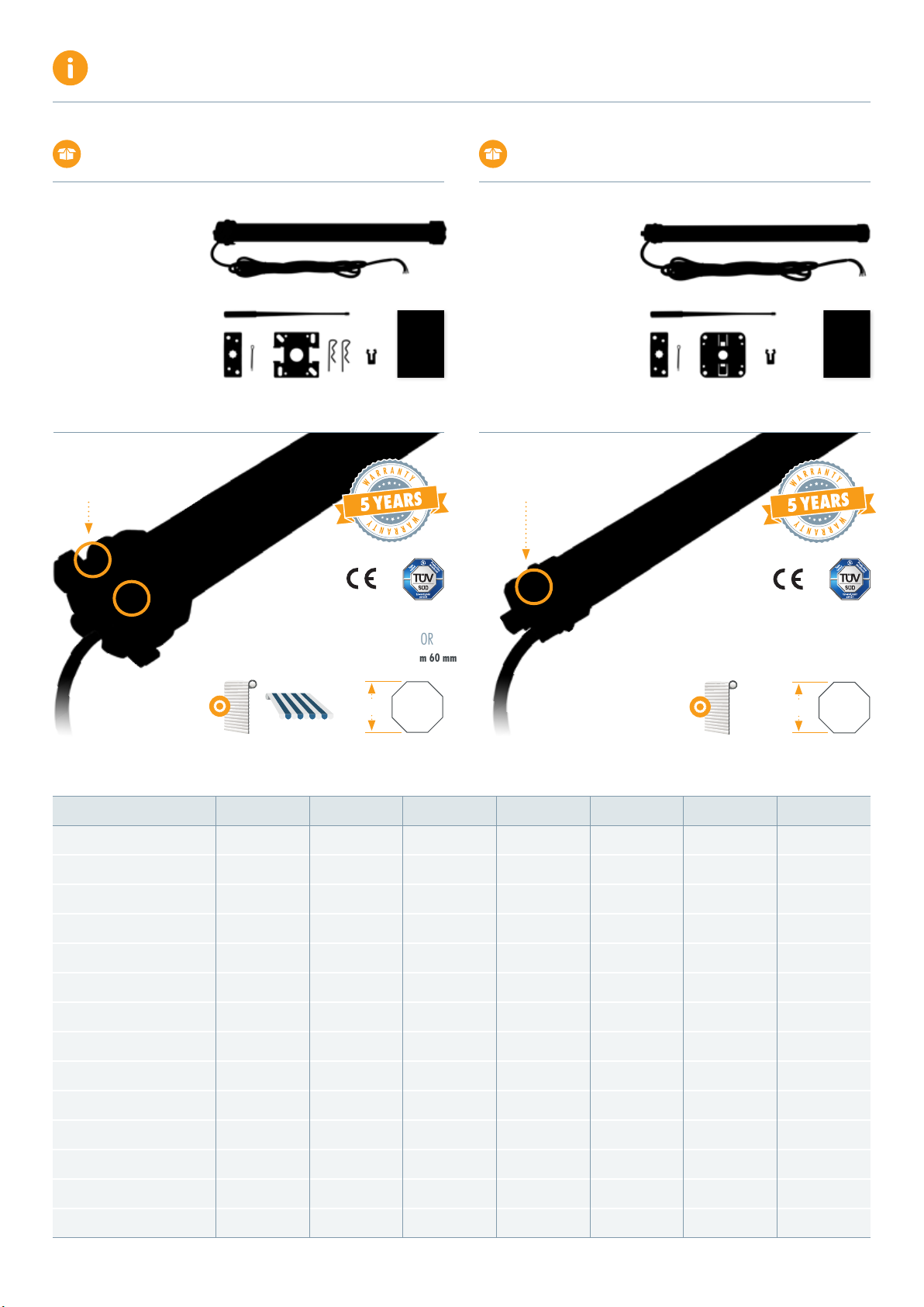
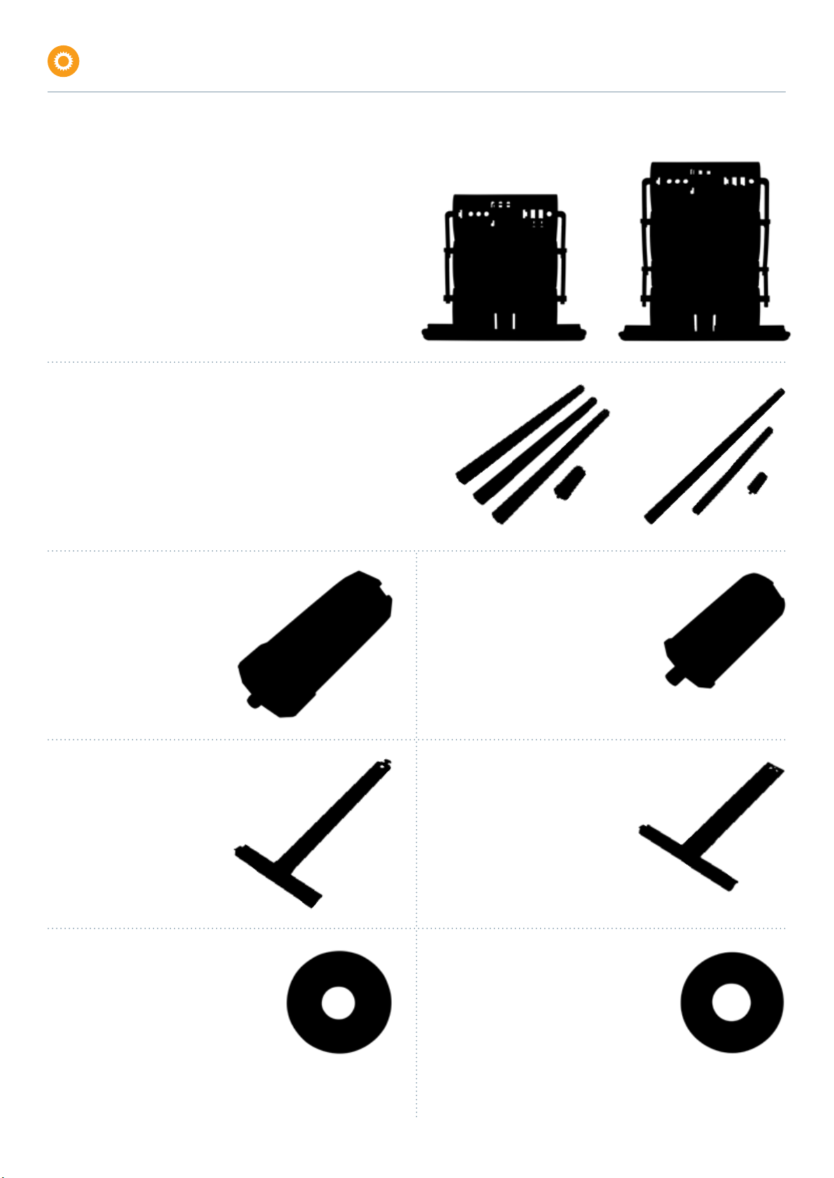
SCOPE OF DELIVERY – MOTOR TYPE 3T45
1Motor
2Limit switch adapter
3Shaft adapter
4Connection cable 3 meters
5Adjustment pin
6Universal bearing & cotter pin
7Cover cap bearing
8Securing bracket
9Manual
2 31
5
4
6 7 8 9
SCOPE OF DELIVERY – MOTOR TYPE 3T35
1Motor
2Limit switch adapter
3Shaft adapter
4Connection cable 3 meters
5Adjustment pin
6Universal bearing & cotter pin
7Clip bearing
8Securing bracket
9Manual
2 31
5
4
6 7 8 9
SUITABLE FOR
8-sided Shafts from 60 mm
Ø60 mm
APPLICATION
Motorized shutters & awnings
APPLICATION
Motorized shutters
SUITABLE FOR
8-sided Shafts from 40 mm
Ø40 mm
Limit switch Limit switch
Emission sound pressure level LpA ≤70 dB(A)
FUNCTION OVERVIEW
3T-MOTORS Tubular motors | Function overview
Motor type
Torque (Nm)
Traction power (kg)
Max. PVC shutter area (m²)
Max. ALU shutter area (m²)
Power (W)
Turn Speed (U/min)
Limit switch capacity (min)
Operating voltage (V AC)
L1 Total motor length (mm)
L2 Installation length (mm)
Connection line (m)
Max. Runtime (min)
Protection class
EAN
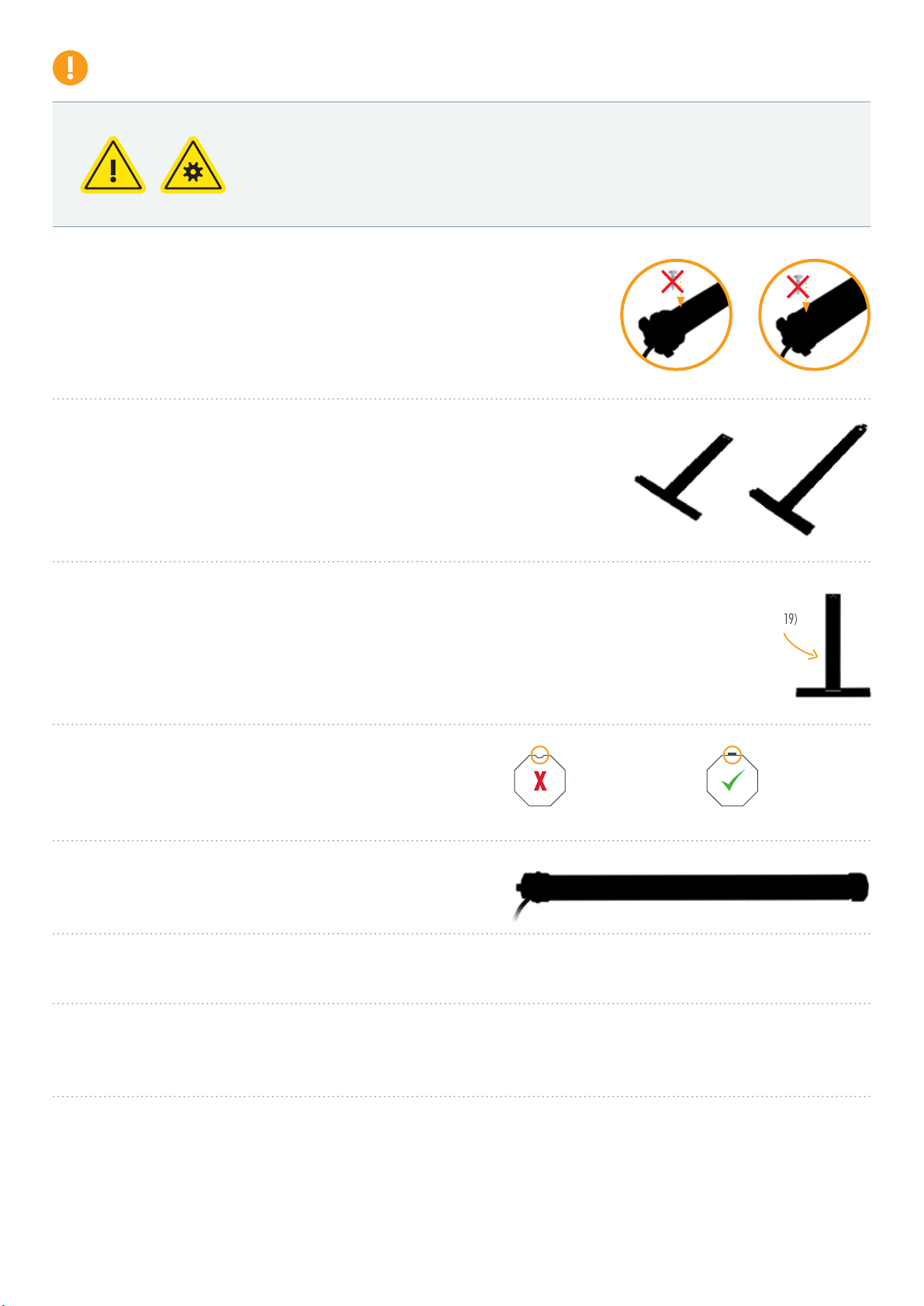
6
•Do not expose the tubular motor to crushing, impact, falling or contact with any liquids.
Do not punch holes in the entire length of the tube (motor casing) or attach screws to it.
•Please use suitable suspension springs to fasten the roller shutter curtain to the roller shutter shaft.
You will nd suitable suspension springs on page 19 and in our store under mounting accessories.
•Important for motor type 3T35 (SW40):
It is essential to use mini suspension springs for motor operation. These special mini springs protrude only approx.
1 mm into the shaft. This allows the shaft to rotate freely. When using commercially available suspension springs
the motor housing is left with grinding marks because the suspension pin protrudes too far into the roller shutter shaft,
which leads to damage and destruction of the motor.
•For steel shafts with a width across ats of 40 mm (SW40), only use shafts with
an external fold. Steel shafts with an internal fold will damage and destroy the motor.
•Grinding marks of any kind on the motor housing will void the warranty.
•The inspection cover of the roller shutter box must be easily accessible and removable.
•We recommend using a tubular motor with a power 10% higher than the weight of the shutter,
to compensate for the frictional resistance of the rail guide. > See Guideline / Determine torque (page 3)
•The motor is designed for short-time operation (4 min). It has an internal thermal circuit breaker which interrupts
the power supply in the event of overheating, e.g. as a result of continuous operation. The cooling phase is min. 10 min,
the thermal switch resets automatically. Regular operation is only possible after the the motor has cooled down completely.
Mini suspension springs (Page 19)
8-sided shaft SW40
with external fold
Do not use
8-sided shaft SW40
with internal fold!
Before installation, all non-essential electrical wiring must be removed, all mechanisms
that are not necessary for motorized operation must be deactivated.
INSTALLATION NOTES
3T-MOTORS Tubular motors | Installation notes

7
INSTALLATION SHUTTER MOTOR
Installation situation
1Counter bearing*
2Ball bearing*
3Roller capsule*
4Shutter shaft*
5Suspension spring*
6Shaft adapter
7Tubular motor
8Limit switch adapter
10 Limit switches
10 Engine mount
11 Shutter curtain*
* Accessories; not included
1Prepare power connection:
•The mains connection cable of the drive must be laid internally in the empty conduit up to the junction box.
The local electrical regulations must be observed.
2Select motor bearing:
•Two motor bearings are supplied with motor type 3T45 and 3T35: Universal bearing (3T45/3T35) and cover cap bearing (3T45) / clip bearing (3T35).
•Use one of the two motor bearings depending on the installation situation.
1 2 3 4 5 6 7 8 9 10
11
Please note:
•The motor can be installed on the right-hand side as well as on the left-hand side.
If the direction of rotation is reversed, please exchange the wires for the up and down direction.
•The setting of the end positions is only possible in the installed state (motor in shutter shaft).
•Never place screws in the area of the tube motor, as they will damage the motor.
•Engine damage caused by improper use or unprofessional installation,
lead directly to loss of warranty.
INSTALLATION INSTRUCTIONS
3T-MOTORS Tubular motors | Installation instructions
8
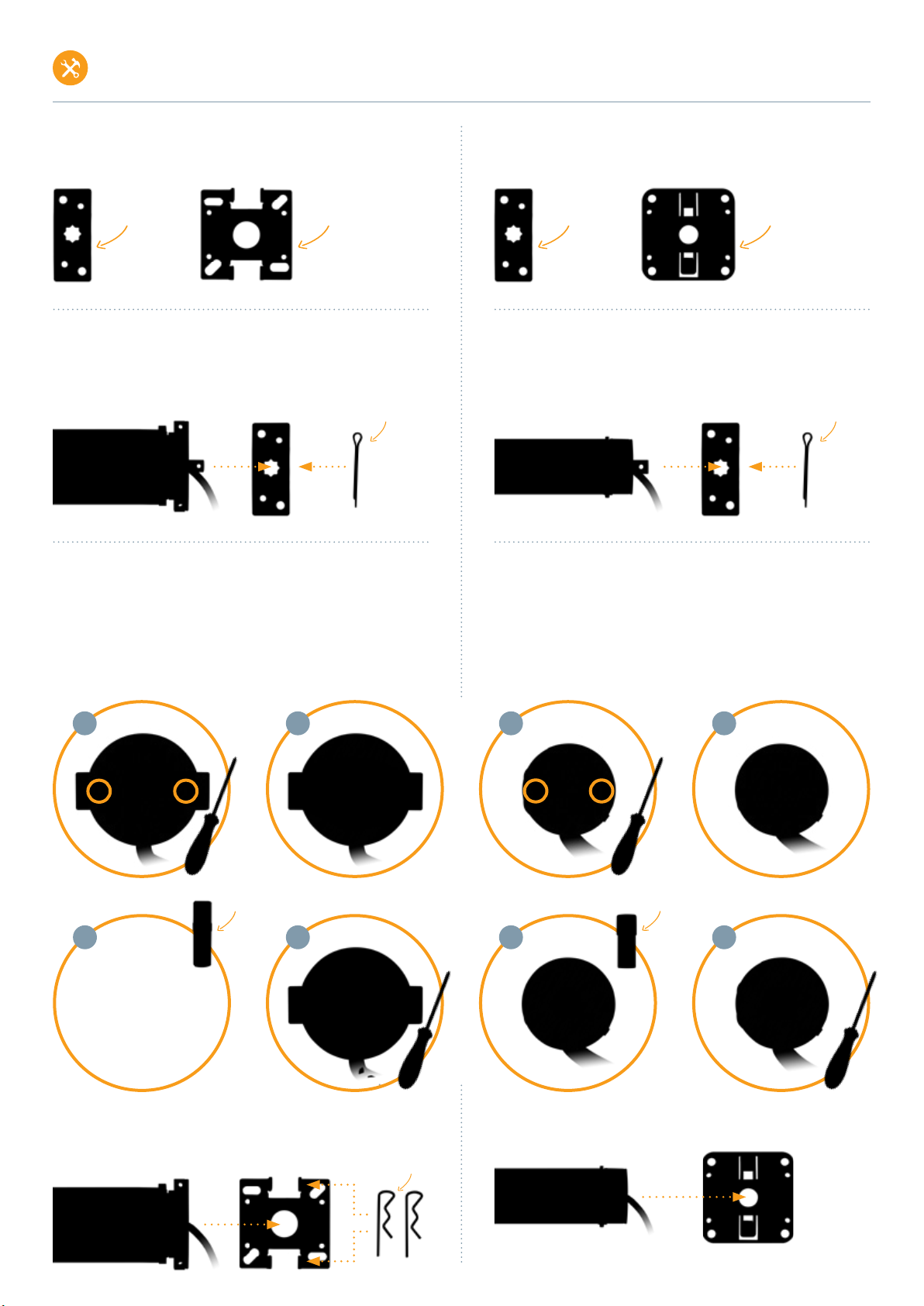
Motor type 3T45
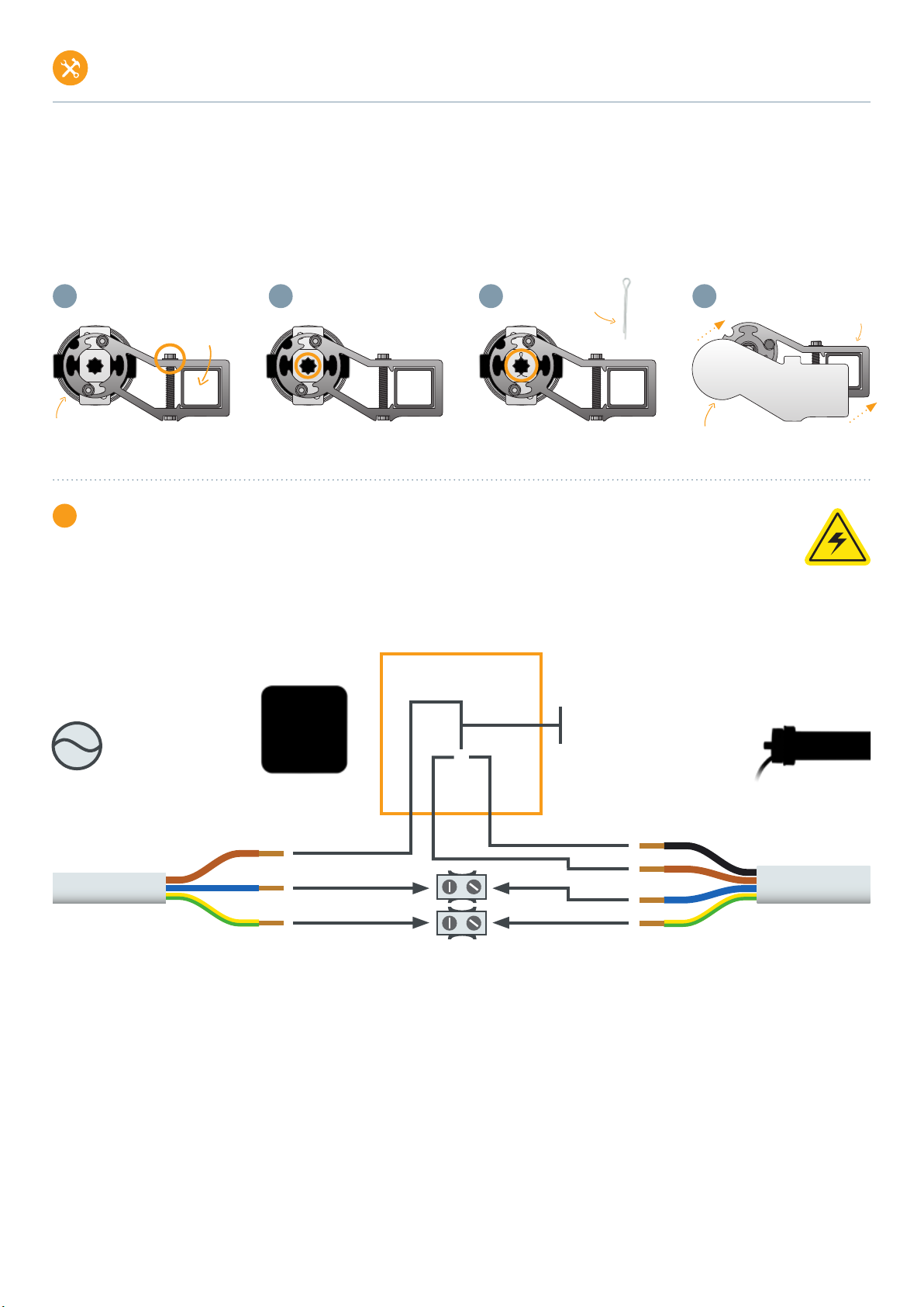
Installation with universal bearing or cover cap bearing
Installation with universal bearing:
•Push the motor with the square into the opening of the bearing
and secure with safety pin.
Installation with cover cap bearing:
•Remove screws from metal plate on motor head >g. 2.1
•Remove metal plate >g. 2.2
•Remove motor square spigot >g. 2.3
•Reattach metal plate >g. 2.4
•Slide motor type 3T45 without square spigot into cover cap bearing
and secure with both securing clips.
Motor type 3T35
Installation with universal bearing or clip bearing
Installation with universal bearing:
•Push the motor with the square into the opening of the bearing
and secure with cotter pin.
Installation with clip bearing:
•Remove screws from metal plate on motor head >g. 2.5
•Remove metal plate >g. 2.6
•Remove motor square spigot >g. 2.7
•Reattach metal plate >g. 2.8
•Engage motor type 3T35 without square spigot in clip bearing.
2.1 2.2
2.3 2.4
Square spigot
2.62.5
2.82.7
Square spigot
Cotter pin
Universal bearing Cover cap bearing
Cotter pin
Securing clips
Universal bearing Clip bearing
3T-MOTORS Tubular motors | Installation instructions
INSTALLATION INSTRUCTIONS

9
3Remove shutter shaft:
•Lower the roller shutter.
•Open the cover of the roller shutter box.
•Release the suspension springs from the roller shutter shaft.
•Lift roller shutter shaft incl. ball bearing out of the holder.
4Prepare motor for installation:
•Push limit switch adapter ush against motor head. >g. 4.1 / 4.2
•Secure the shaft adapter with the supplied securing bracket. >g. 4.3 / 4.4
•Push the motor into the roller shutter shaft without using force (never knock it in). The fold of the shaft must lie over the recess in the shaft adapter. >g. 4.5 / 4.6
•Make sure that the roller shutter shaft is ush with the motor head limit switch adapter. >g. 4.7 / 4.8
5Mount bearings:
•Remove old wall bearing on motor side (left or right installation possible).
•Mount motor bearing at this point (2 mounting options: Universal bearing and cover cap bearing / clip bearing).
•Please mount the bearings so that the limit switches are freely accessible.
•Make sure that the roller shutter motor with the shaft unit sits horizontally in the roller shutter box.
6Mount motor with shaft unit:
•Insert the motor head (with the entire shaft unit) into the motor bearing and secure it with the supplied cotter pin or securing clips (Cover cap bearing).
4.1
Limit switch adapter
Motor head 4.2 4.3
Securing bracket
4.4
Click
Shaft adapter
4.5
Roller shutter shaft
4.6 4.7 4.8
Fold
Recess
wrong right
3T-MOTORS Tubular motors | Installation instructions
INSTALLATION INSTRUCTIONS

10
•On the opposite side of the motor, push the roller capsule out of the roller shutter shaft until it ts into the ball bearing inserted in the wall bearing.
•Fix roller capsule to roller shutter shaft with self-tapping screw. Position the screw at a punched hole. This prevents the screw from slipping.
7Shutter motor wiring:
•Connect the roller shutter motor and switch (or timer) to the mains.
•The electrical connection of the roller shutter motor and control unit may only be carried out by qualied personnel.
•If the drive should run in the opposite direction after installation, the motor’s upstream and downstream leads (brown + black) must be turned.
The connection diagram of time switches differs from this circuit diagram!
Please refer to the corresponding manual for the connection diagram.
Roller capsule
Wall bearing +
Ball bearing
Power grid
230 V / 50 Hz
1) brown / black = L1 / Phase
2) blue = N Neutral conductor
3) green/yellow = PE Protective conductor
1) black = Departure or ascent
2) brown = Departure or ascent
3) blue = N Neutral conductor
4) green/yellow = PE Protective conductor
2 (N)
1 (Up/Down)
2 (Up/Down)
3 (N)
4 (PE)
3 (PE)
1 (L1)
Shutter motor
230 V / 50 Hz
3T-MOTORS Tubular motors | Installation instructions
INSTALLATION INSTRUCTIONS
11
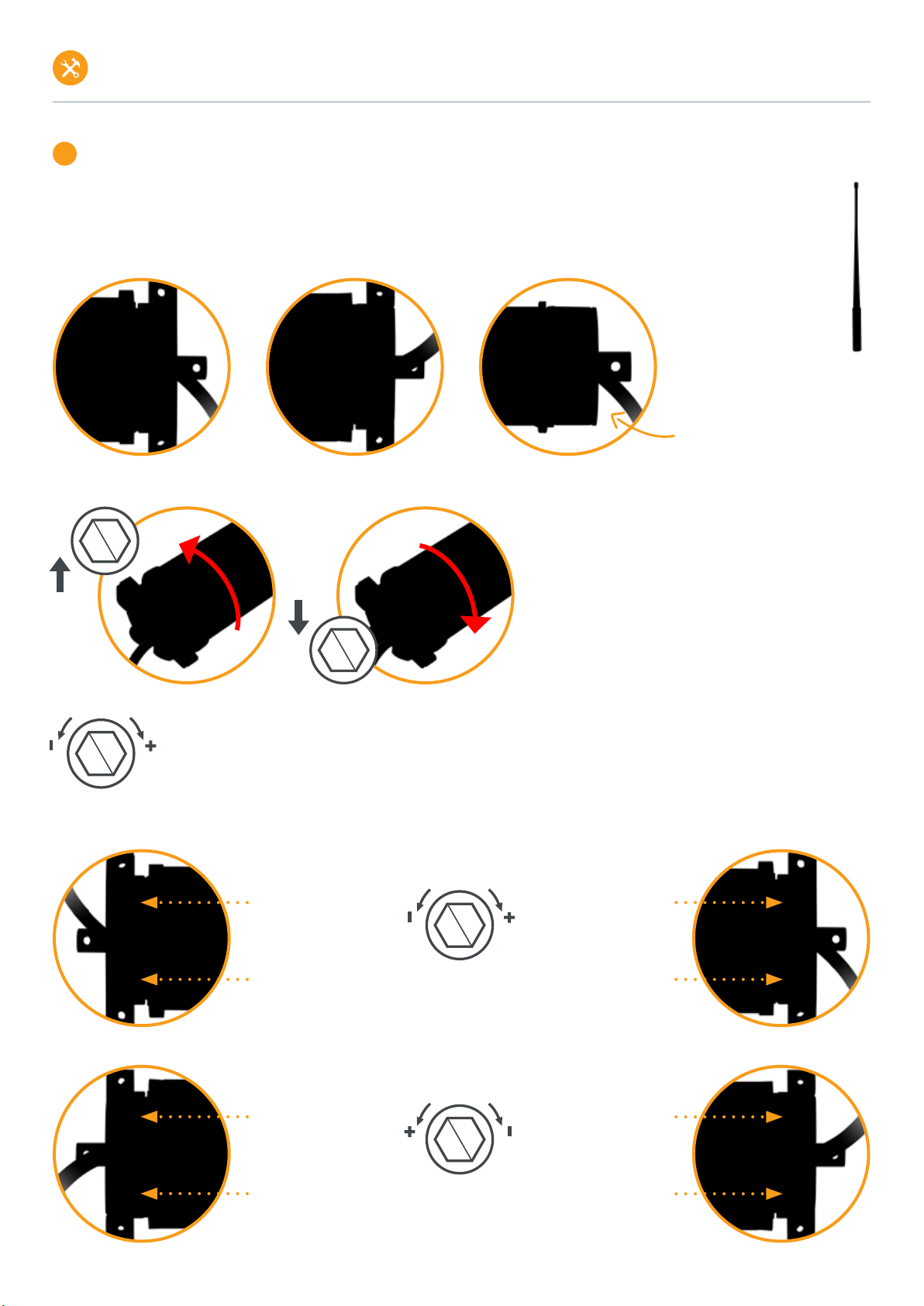
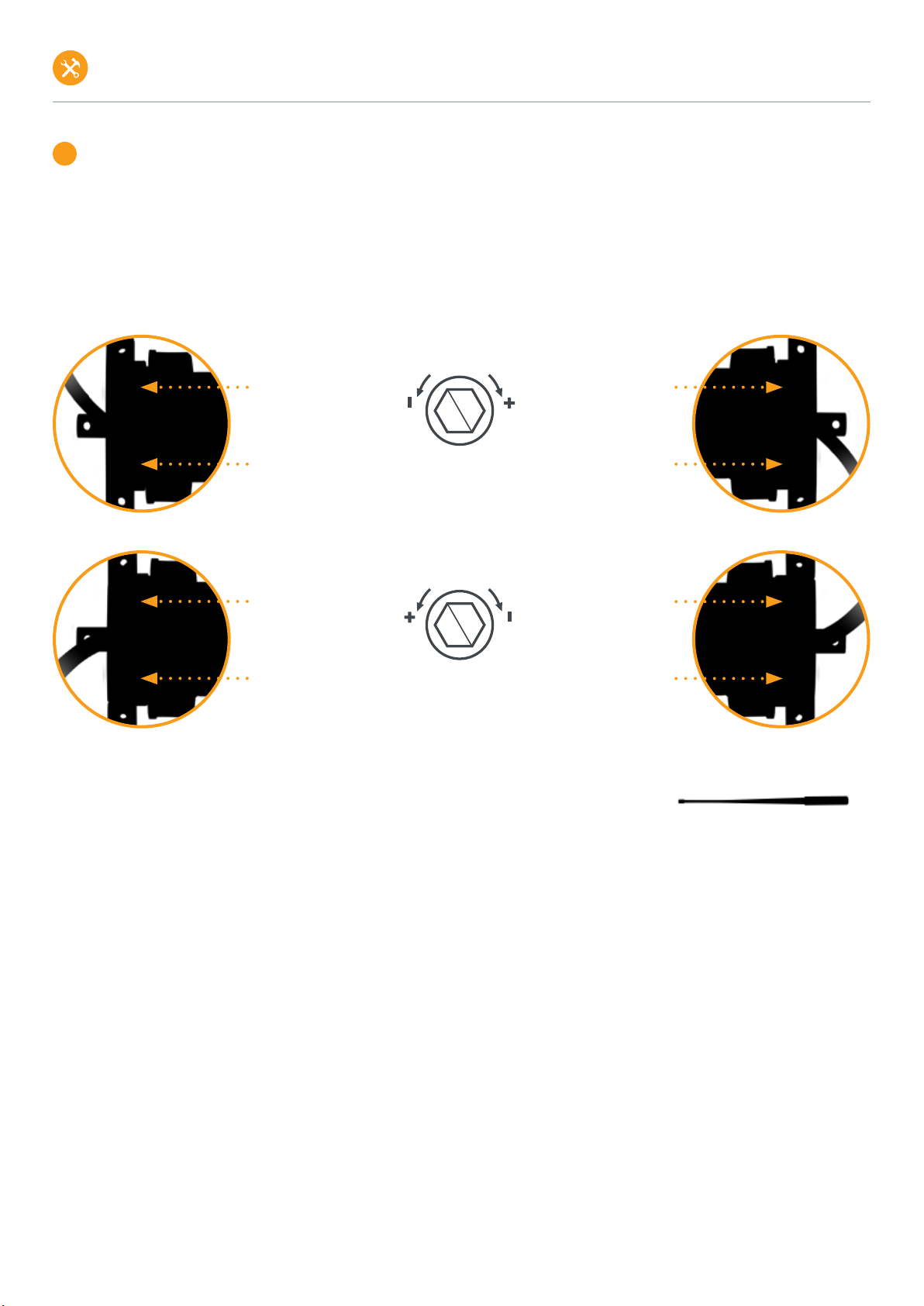
8Setting the end positions:
Explanation of the limit switch screws
There are 2 limit switch screws on the motor head. One limit switch screw is responsible for the upper end position, the other for the lower end position.
The end positions can be adjusted by turning the limit switch screws with the adjustment pin.
Adjustment pin
The arrows with PLUS and MINUS apply to both limit switch screws and show you in which direction you must turn the adjusting pin to switch
off the motor sooner or later. Turning the limit switch screw in the PLUS direction after switching off allows the motor to continue moving step
by step in the corresponding direction. Turning the limit switch screw in the MINUS direction during travel causes the motor to switch off earlier.
For motor type 3T45 / power cable to the front, the PLUS and MINUS directions change (see marking on the motor head).
On 3T35 motor types, the limit
switch screws are located on one
side of the motor head only.
Motor type 3T45 / Power cable to rear Motor type 3T35 / Power cable to rearMotor type 3T45 / Power cable to front
The straight up and down arrows indicate the direction of rotation
of the motor and shaft and thus show you for which end position
the limit switch screw next to it is responsible. Depending on
whether the direction of rotation leads to unrolling or rolling up of
the roller shutter, the limit switch screw is responsible for the lower
or upper end position (unrolling > lower end position, rolling up >
upper end position).
Left installation
Limit switch screw white:
Lower end position
Limit switch screw red:
Upper end position
Right installation
Limit switch screw red:
Lower end position
Limit switch screw white:
Upper end position
Power cable to rear
Left installation
Limit switch screw red:
Upper end position
Limit switch screw white:
Lower end position
Right installation
Limit switch screw white:
Upper end position
Limit switch screw red:
Lower end position
Power cable to front
Direction of rotation
Limit switch screw
Direction of rotation
Limit switch screw
INSTALLATION INSTRUCTIONS
3T-MOTORS Tubular motors | Installation instructions

12
1. Setting the lower end position
•Do not fasten the roller shutter curtain!
Detach all suspension springs from the roller shutter shaft!
•Move the motor + shaft in the downward direction until the lower limit switch-off occurs automatically
and the motor stops.
•Move motor + shaft upwards.
While the motor is moving upwards, turn the adjustment pin on the limit switch screw for the upper limit
position in the MINUS direction (up to 100 turns, depending on the motor type) until the motor switches
off after approx. 4 turns.
This prevents the roller shutter from being pulled out of the guide rails when the upper end position is set.
•Move motor + shaft in downward direction to the lower end position until the motor stops automatically.
•If the shaft has to be turned a little to hook in the suspension springs, use the adjustment pin on the
limit switch screw for the lower end position in the PLUS direction. This causes the motor to turn the shaft
stepwise. The rectangular openings in the shaft for hooking in the suspension springs should point forward
and be easily accessible.
•Hang the roller shutter curtain on the roller shutter shaft using the suspension springs.
2. Setting the upper end position
•Allow the motor + roller shutter to move upwards until the motor stops automatically at the previously set
upper end position.
•To set the upper end position, turn the adjustment pin on the limit switch screw for the upper end position
in the PLUS direction to raise the motor + roller shutter further. The upper end position should be that the
roller shutter stops approx. 3 cm before the roller shutter box. Reason is the expansion of the roller shutter
due to the temperature difference in summer and winter.
•After setting the end positions, lower and raise the motor + shutter to check the set end positions.
Note heat generation
The end position setting without
shutter curtain load leads to more
heat generation in the motor. This
is normal behavior and does not
result in damage to the motor. If
the motor heats up too much, the
thermal protection switch of the motor
is automatically triggered. After a
cooling phase of at least 10 minutes,
the motor is ready for operation again.
Special case: Roller shutter rolls down in front of motor + shaft
If the roller shutter curtain rolls in front of the motor and shaft, the responsibilities of the limit switch screws for the upper and lower end positions are reversed.
See illustration of left-right installation on page 11: upper end position > lower end position / lower end position > upper end position.
Adjustment pin
is required
3T-MOTORS Tubular motors | Installation instructions
INSTALLATION INSTRUCTIONS

13
MOUNTING INSTRUCTIONS FOR 3T-MOTORS MINI-TUBE MOTORS MOTOR TYPE 3T35
Use proper suspension springs:
•To fasten the roller shutter curtain to the roller shutter shaft, please be sure to use
suitable suspension springs for motor operation. These special mini suspension springs only protrude
approx. 1 mm into the shaft. This allows the shaft to rotate freely. When commercially
springs are used, there will be grinding marks on the motor housing because the suspension pin
protudes too far into the roller shutter shaft, which leads to damage and destruction of the motor.
In case of any kind of grinding marks on the motor housing, the warranty claim is void.
•Mini suspension springs > Optional tubular motor accessories (page 19)
Use correct roller shutter shaft with external fold:
•For steel shafts with a width across ats of 40 mm (SW40), only use shafts with
an external fold. Steel shafts with an internal fold will damage and destroy the motor.
Explanation:
•Avoid overstressing and resulting premature aging of the motor by using the correct suspension
springs and the correct roller shutter shaft with external fold!
•Keep in mind that the motor housing has a diameter of 35 mm and the roller shutter shaft SW40
has an outer diameter of 40 mm. When using commercially available springs or roller shutter shafts
with internal fold, the motor housing will be left with grinding marks, since the suspension pin or the
fold protrude too far into the roller shutter shaft. Contrary to its intended use, the motor runs
permanently against an overload and outside its characteristic data.
•Matching roller shutter shafts SW40 > Optional tubular motor accessories (page 19)
Mini Suspension spring
8-sided shaft SW40
with external fold
Do not use
8-sided shaft SW40
with internal fold!
Suspension spring
INSTALLATION INSTRUCTIONS
3T-MOTORS Tubular motors | Installation instructions

14
INSTALLATION AWNING MOTOR
1Preparation:
•Screw in awning & secure with straps or ropes.
•Remove awning from wall bracket & place on safe surface.
2Prepare motor for installation:
•Slide limit switch adapter ush against motor head. >g. 2.1 / 2.2
•Secure the shaft adapter with the supplied securing bracket. >g. 2.3 / 2.4
3Installation awning motor:
•Remove the cover to access the side bearing (also awning bracket)
and fastening screws. >g. 3.1
•Loosen the screw that secures the side bearing to the support tube. >g. 3.2
•Remove all screws connecting the side bearing
and the crank mechanism. >g. 3.3
•Remove the side bearing from the support tube. >g. 3.4
•Remove the crank mechanism. >g. 3.5
Attention:
Awning arms are under strong tension!
2.1
Limit switch adapter
Motor head 2.2 2.3
Securing bracket
2.4
Click
Shaft adapter
Side bearing
Cover
3.1
Support tube
Side bearing
3.2 3.2 3.4
Crank mechanism
•Remove the shaft capsule from the shaft. >g. 3.6
If the shaft capsule is tight, use a hammer and screwdriver.
Be careful not to damage the shaft.
•Push the awning motor with shaft adapter rst into the shaft. >g. 3.7
•Make sure motor head & limit switch adapter are ush in shaft.
•Screw the universal bearing onto the side bearing on the side
facing the awning shaft. >g. 3.8
3.5 3.6 3.7 3.8
Support tube
Shaft capsule
Shaft &
wound up
Awning
Universal
bearing
Shaft &
wound up
Awning
INSTALLATION INSTRUCTIONS
3T-MOTORS Tubular motors | Installation instructions
15
•Slide the side bearing with universal bearing onto the support tube & fasten. >g. 3.9
•Ensure that the motor square spigot is properly engaged in the universal bearing. >g. 3.10
•Secure the motor square spigot with the supplied cotter pin. >g. 3.11
•Attach the cover to the side bearing. >g. 3.12
•Install awning & release fuses.
4Awning motor wiring:
•Connect the awning motor and switch (or timer) to the mains.
•The electrical connection of the awning motor and control may only be carried out by qualied personnel.
•If the drive should run in the opposite direction after installation, the motor’s upstream and downstream leads (brown + black) must be turned.
3.9 3.10 3 .11
Side bearing &
Universal bearing
Support tube
Cotter pin Side bearing
Cover
3.12
Awning motor
230 V / 50 Hz
INSTALLATION INSTRUCTIONS
3T-MOTORS Tubular motors | Installation instructions
Power grid
230 V / 50 Hz
1) brown / black = L1 / Phase
2) blue = N Neutral conductor
3) green/yellow = PE Protective conductor
1) black = Departure or ascent
2) brown = Departure or ascent
3) blue = N Neutral conductor
4) green/yellow = PE Protective conductor
2 (N)
1 (Up/Down)
2 (Up/Down)
3 (N)
4 (PE)
3 (PE)
1 (L1)
16
5Setting the end positions:
Explanation of the limit switch screws
There are 2 limit switch screws on the motor head. One limit switch screw is responsible for the „EXTEND” position, the other for the „RETURN” position.
By turning the limit switch screws with the adjustment pin, the positions of the limit switch can be adjusted.
A detailed description of the limit switch screws and the markings on the motor head can be found on page 11.
1. Setting the position „EXTEND”
•Set the switch to „EXTEND”, awning moves OUT.
•Run the tubular motor in the „EXTEND” direction until the end switch-off occurs.
•If the motor is to continue moving, turn the adjustment pin on the „EXTEND” limit switch screw in the PLUS direction until the desired position is reached.
2. Setting the position „RETURN”
•Set the switch to „RETURN”, awning moves IN.
•Run the tubular motor in the „RETURN” direction until the end switch-off occurs.
•If the motor is to continue moving, turn the adjustment pin on the „RETURN” limit switch screw in the PLUS direction until the desired position is reached and
the awning is fully retracted.
If the awning motor travels too far:
•While the tubular motor is moving in the relevant direction (EXTENDING or RETURNING), turn the adjusting pin on the relevant limit switch screw in the MINUS
direction until the tubular motor switches off. If this is not possible, stop with the switch.
•After switching off by turning the limit switch screw in the PLUS direction, allow the tube motor to move to the desired end position.
•If this does not work, run the tube motor again in the opposite direction, stop and repeat this procedure.
Left installation
Limit switch screw white:
„RETURN”
Limit switch screw red:
„EXTEND”
Right installation
Limit switch screw red:
„RETURN”
Limit switch screw white:
„EXTEND”
Power cable to rear
Left installation
Limit switch screw red:
„EXTEND”
Limit switch screw white:
„RETURN”
Right installation
Limit switch screw white:
„EXTEND”
Limit switch screw red:
„RETURN”
Power cable to front
Direction of rotation
Limit switch screw
Direction of rotation
Limit switch screw
Adjustment pin is required
INSTALLATION INSTRUCTIONS
3T-MOTORS Tubular motors | Installation instructions

17
TROUBLESHOOTING
WHAT TO DO WHEN ...
... the motor does not run?
•Mains voltage is missing.
•Check correct connection of the control (switch or timer).
... the motor is running in the wrong direction?
•Swap the two wires for the direction of rotation (brown + black).
... the motor does not switch off at the set point?
•Check t of limit switch adapter (must be ush with motor head and shutter shaft).
•Roller capsule is not xed or roller shutter shaft is too short.
•Set limit switch screw correctly (see instructions):
MINUS turning during travel shortens the travel distance; PLUS turning after switch-off extends the travel distance.
... the motor does not switch off at all?
•Engine was run in removed state (limit switches only work in installed state).
•Check t of limit switch adapter (must be ush with motor head and shutter shaft).
•Limit switches are too far apart:
•Determine limit switch screws according to explanation on page 11.
•Do not fasten roller shutter armor!
•Only allow the shutter shaft to be rotated by the motor.
•While driving, turn the relevant limit switch screw in the MINUS direction (up to 100 turns depending on the motor type) until the motor switches off.
•Then allow the roller shutter shaft to rotate in the opposite direction and turn the other limit switch screw in the MINUS direction until the motor switches off.
•Repeat the entire process (Drive up turn MINUS / Drive down turn MINUS) until the motor switches off in both directions after 2 - 3 rotations.
•Then allow the roller shutter shaft to rotate downwards until the limit switch is switched off. After switching off, if necessary, continue to move the motor by
turning the relevant limit switch screw PLUS to position the holes for the suspension springs.
... the motor stops running after continuous operation?
•The thermal protection switch of the motor has tripped. After a cooling phase (min. 10 min.), the motor is ready for operation again.
... the motor turns in only one direction?
•Check correct connection of the control (switch or timer).
•Check the setting of the limit switches.
... the motor does not operate at the specied speed?
•Check roller shutter weight; if necessary, correct inclined installation of roller shutter shaft or Eliminate mechanical friction in the roller shutter box or rail guide.
3T-MOTORS Tubular motors | Troubleshooting

18
EU Konformitätserklärung
Wir, die Firma 3T Components GmbH & Co. KG
Bahnhofstr. 34
55578 Wallertheim
Deutschland
erklären in alleiniger Verantwortung, dass das weiter unten genannte Produkt
Geräteart:Rohrmotor mit mechanischen Endschaltern
Modell Artikelnummer
3T35-10 344
3T35-13 345
3T45-10 346
3T45-20 348
3T45-30 349
3T45-40 350
3T45-50 351
die grundlegenden Anforderungen der aufgeführten EG/EU-Richtlinien erfüllt:
Maschinenrichtlinie 2006/42/EG
EMV-Richtlinie 2014/30/EU
RoHS-Richtlinie 2011/65/EU / Delegierte Richtlinie (EU) 2015/863
WEEE-Richtlinie 2012/19/EU
angewandte Standards und Verordnungen:
EN 60335-1:2012/A13:2017
EN 60335-2-97:2006/A12:2015
EN 55014-1:2017
EN 55014-2:2015
EN 61000-3-2:2014
EN 61000-3-3:2013
Bevollmächtigter zur Zusammenstellung der technischen Unterlagen:
Name,Position:Patrick El Hadj-Henni, Geschäftsführer
Wallertheim, 02.04.2018
……………………………. …………………………..
Datum Unterschrift
3T-MOTORS Tubular motors | EU Declaration of Conformity
19
OPTIONAL ACCESSORIES TUBULAR MOTORS
ANTI-LIFT DEVICE | SHUTTER SHAFTS | ROLLER CAPSULE | SUSPENSION SPRINGS | BALL BEARINGS
OCTOCLICK Anti-lift device 2-link / 2,5-link
•Burglar-resistant
•The pushing up of a closed motorized roller shutter is prevented
•For tubular motors with electronic or mechanical limit switching
•For 50 mm (SW50) and 60 mm (SW60) octagonal shafts
• For roller shutter armor with thickness 8 mm + 14 mm (mounting prole can be rotated)
• Made of glass ber reinforced polyamide
•No tooling required
Shutter shafts SW60 / SW40
8-sided steel shafts / shaft sets
•SW60 (diameter: 60 mm) up to roller shutter box width:
110 cm / 150 cm / 190 cm / 270 cm / 310 cm / 350 cm
•SW40 (diameter: 40 mm) up to roller shutter box width:
110 cm / 140 cm / 160 cm
Suspension spring Maxi
Required when using roller shutter motors
• Maxi spring up to 65 mm prole height
•For roller shutter shaft SW60
•Powder coated
•Anti-burglary effect
•Pick up width: 100 mm
•Total length: 215 mm
Suspension spring Mini
Required when using roller shutter motors
•For roller shutter shaft SW40
•Powder coated
•Anti-burglary effect
•Pick up width: 100 mm
•Total length: 140 mm
Ball bearing Maxi
Maxi ball bearing for use in roller shutter bearing
•Outer diameter: 40 mm
•Inner diameter: 12 mm
•Specialized trade quality
Ball bearing Mini
Mini ball bearing for use in roller shutter bearing
•Outer diameter: 28 mm
•Inner diameter: 10 mm
•Specialized trade quality
Roller capsule long SW60
High quality product
•Length: 140 mm
•Length Steel pin: 12 mm
•PVC
Roller capsule long SW40
High quality product
•Length: 80 mm
•Length Steel pin: 9,8 mm
•PVC
3T-MOTORS Tubular motors | Optional accessories tubular motors

bit.ly/youtube-3TComponentswww.facebook.com/3TComponents www.instagram.com/3tcomponents twitter.com/3TComponents
INTELLIGENT
DRIVES &
CONTROLS
FOR SHUTTERS
AND AWNINGS
Service and
Quality
make the
difference!
3T-Components GmbH & Co. KG
Bahnhofstr. 34
55578 Wallertheim
Email: info@3t-components.de
Tel: +49 (0) 6732-600 03 69
Fax: +49 (0) 6732-600 54 30
www.3t-components.de
Opening hours:
Monday – Friday / 8:00 –17:00
Social Media Links
Info, news and tips on roller shutters, awnings, smart home and more:
This manual suits for next models
8
Table of contents
Other 3T-Components Engine manuals

3T-Components
3T-Components 3T-MOTORS 3T45-E Manual

3T-Components
3T-Components 3T-MOTORS 3T45-SD Manual

3T-Components
3T-Components 3T-MOTORS 3T45-20 Manual

3T-Components
3T-Components 3T-MOTORS 3T45-RB Manual

3T-Components
3T-Components 3T-MOTORS 3T45-10R Manual

3T-Components
3T-Components 3T-MOTORS 3T35-R Manual
Popular Engine manuals by other brands


Sole Diesel
Sole Diesel SK-60 Operator's manual

Chrysler
Chrysler 225 Operating maintenance installation

ASA Electronics
ASA Electronics DA VINCI 40 ST manual

WÄRTSILÄ
WÄRTSILÄ RT-flex50-D Maintenance manual

Parsun
Parsun F15/F9.9BM Service manual

UNITED POWER EQUIPMENT
UNITED POWER EQUIPMENT UP152 Operation manual