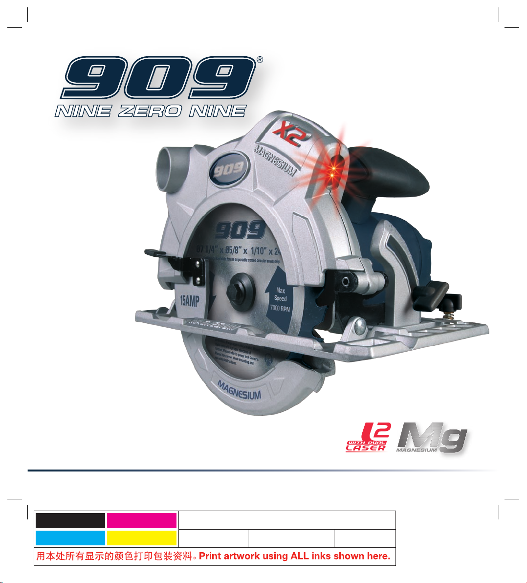
909 LS15CS User manual

Black
Cyan
Magenta
Yellow
Code: LS15CS
Date: 100326 Edition: 2 Op: DCR
INSTRUCTION MANUAL
LS15CS
15 AMP
DUAL LASER
CIRCULAR SAW
WITH MAGNESIUM

2
Warranty 2
Introduction 3
Environmental protection 3
Description of symbols 3
Specifications 3
General safety rules 4
Additional safety rules for laser lights 5
Additional safety rules for circular saws 6
Accessories 7
Unpacking 7
Assembly 7
Know your product 8
Overview 9
Adjusting the cutting depth 9
Adjusting the bevel angle 9
Switching on and off 10
Making a cut 10
Making a pocket cut 10
Using the parallel fence 11
Using the dual laser line system 11
Changing the blade 12
Adjusting the twin laser 12
Maintenance 13
Cleaning 13
General inspection 13
Power cord maintenance 13
Troubleshooting 13
CONTENTS
Warranty Power Tools
For full details please visit us at www.909.com

3
Description of symbols
The rating plate on your tool may show symbols.
These represent important information about the
product or instructions on its use.
Wear hearing protection.
Wear eye protection.
Wear breathing protection.
Double insulated for additional protection.
Tool is listed by Underwriters Laboratories
and listed to Canadian Standards by
Underwriters Laboratories
Specifications
Voltage: 120V ~ 60Hz
Power rating: 15 Amp
No load speed: 5000 min-1
Blade diameter: 7 1/4" (185mm)
Blade teeth: 24 TCT
Blade arbour: 5/8" (16mm)
Blade kerf: 1/8" (2.8mm)
Bevel capacity: 0° to 55°
Depth of cut at 90°: 2 3/8" (60mm)
Depth of cut at 45°: 1 7/8" (42mm)
Depth of cut at 55°: 1 3/10" (34mm)
Laser type: Class 2, mains operated
Electrical insulation: Double insulated
Tool weight: 11.9 lbs (5.4kg)
This tool is double insulated. There are two independent
barriers of insulation to protect you from the possibility of
electric shock.
The sound intensity level for the operator may exceed
85dB(A) and sound protection measures are necessary.
Introduction
Your new 909 power tool will more than satisfy
your expectations. It has been manufactured under
stringent 909 Quality Standards to meet superior
performance criteria.
You will find your new tool easy and safe to operate,
and, with proper care, it will give you many years
of dependable service.
CAUTION. Carefully read through this entire Instruction
Manual before using your new 909 Power Tool. Take
special care to heed the Cautions and Warnings.
Your 909 power tool has many features that will make
your job faster and easier. Safety, performance, and
dependability have been given top priority in the
development of this tool, making it easy to maintain
and operate.
Environmental protection
Recycle unwanted materials instead
of disposing of them as waste. All tools,
hoses and packaging should be sorted,
taken to the local recycling centre and
disposed of in an environmentally safe way.
WARNINGS.
1. Do not attempt to change the position of the laser under
any circumstances, it has been set at the factory and is
accurately focused on the centre of the saw blade.
2. It may be more difficult to see the laser line in conditions
of bright sunshine and on certain surfaces.
E205892

4
General safety rules
WARNING Read and understand all instructions. Failure
to follow all instructions listed below, may result in electric
shock, fire and/or serious personal injury.
Save these instructions
Work Area
1. Keep your work area clean and well lit. Cluttered
benches and dark areas invite accidents.
2. Do not operate power tools in explosive atmospheres,
such as in the presence of flammable liquids, gases,
or dust. Power tools create sparks which may ignite the
dust or fumes.
3. Keep bystanders, children, and visitors away while
operating a power tool. Distractions can cause you to
lose control.
Electrical Safety
1. Double Insulated tools are equipped with a polarized
plug (one blade is wider than the other.) This plug will
fit in a polarized outlet only one way. If the plug does not
fit fully in the outlet, reverse the plug. If it still does not fit,
contact a qualified electrician to install a polarized outlet.
Do not change the plug in any way. Double Insulation
eliminates the need for the three wire grounded power
cord and grounded power supply system.
2. Avoid body contact with grounded surfaces such as
pipes, radiators, ranges and refrigerators. There is an
increased risk of electric shock if your body is grounded.
3. Don’t expose power tools to rain or wet conditions.
Water entering a power tool will increase the risk of
electric shock.
4. Handle the cord carefully. Never use the cord to carry
the tools or pull the plug from an outlet. Keep cord away
from heat, oil, sharp edges or moving parts. Replace
damaged cords immediately. Damaged cords increase
the risk of electric shock.
5. When operating a power tool outside, use an
outdoor extension cord marked “W-A” or “W”.
These cords are rated for outdoor use and reduce
the risk of electric shock.
Personal Safety
1. Stay alert, watch what you are doing and use
common sense when operating a power tool.
Do not use tools when tired or under the influence of
drugs, alcohol, or medication. A moment of inattention
while operating power tools may result in serious
personal injury.
2. Dress properly. Do not wear loose clothing or jewelry.
Contain long hair. Keep your hair, clothing, and gloves
away from moving parts. Loose clothes, jewelry or long
hair can be caught in moving parts.
3. Avoid accidental starting. Be sure switch is off
before plugging in. Carrying tools with your finger on
the switch or plugging in tools that have the switch on
invites accidents.
4. Remove adjusting keys or wrenches before turning
the tool on. A wrench or a key that is left attached to a
rotating part of the tool may result in personal injury.
5. Do not overreach. Keep proper footing and balance
at all times. Proper footing and balance enables better
control of the tool in unexpected situations.
6. Use safety equipment. Always wear eye protection.
Dust mask, non-skid safety shoes, hard hat or hearing
protection must be used for appropriate conditions.
Tool Use and Care
1. Use clamps or other practical way to secure and
support the workpiece to a stable platform. Holding
the work by hand or against your body is unstable and
may lead to loss of control.
2. Do not force tool. Use the correct tool for your
application. The correct tool will do the job better and
safer at the rate in which it is designed.

5
3. Do not use tool if switch does not turn it on or off.
Any tool that cannot be controlled with the switch is
dangerous and must be repaired.
4. Disconnect the plug from the power source before
making any adjustments, changing accessories,
or storing the tool. Such preventive safety measures
reduce the risk of starting the tool accidentally.
5. Store idle tools out of reach of children and other
untrained persons. Tools are dangerous in the hands of
untrained users.
6. Maintain tools with care. Keep cutting tools sharp and
clean. Properly maintained tools, with sharp cutting edges
are less likely to bind and are easier to control.
7. Check for misalignment or binding of moving parts,
breakage of parts, and any other condition that may
affect the tools operation. If damaged, have the tool
serviced before using. Many accidents are caused by
poorly maintained tools.
8. Use only accessories that are recommended by the
manufacturer for your model. Accessories that may be
suitable for one tool, may become hazardous when used
on another tool or model.
Service
1. Tools service must be performed only by qualified
repair personnel. Service or maintenance performed by
unqualified personnel could result in a risk of injury.
2. When servicing a tool, use only identical replacement
parts. Follow instructions in the Maintenance section of
this manual. Use of unauthorized parts or failure to follow
Maintenance Instructions may create a risk of electric
shock or injury.
Safety rules for laser lights
The laser guide used in the tool is Class II with a maximum
output of 1mW and a wavelength of 650nm. The laser
guide does not normally present an optical hazard, although
staring at the beam may cause flash blindness.
User information
CAUTION. The use of optical instruments with this laser
product will increase the chance of eye damage.
• Do not stare into the laser beam.
• The laser shall be used and maintained in accordance
with the manufacturer’s instructions.
• Never aim the beam at any person or an object other
than the work piece.
• Always ensure the laser beam is aimed at a sturdy
work piece without a reflective surface (i.e. wood or
rough coated surfaces are acceptable). Bright shiny
reflective sheet or the like is not suitable for laser use
as the reflective surface could direct the beam back at
the operator.
Additional safety rules for circular saws
DANGER! Keep hands away from cutting area and blade.
Keep your second hand on auxiliary handle, or motor
housing. If both hands are holding the saw, they cannot be
cut by the blade.
• Keep your body positioned to either side of the saw
blade, but not in line with the saw blade. Kickback could
cause the saw to jump backwards.
• Do not reach underneath the workpiece. The guard
cannot protect you from the blade below the work.
RAYONNEMENT LASER – NE PAS REGARDER LE RAYON NI
VISUALISER DIRECTEMENT À L’AIDE D’INSTRUMENTS D’OPTIQUE
LASER RADIATION – DO NOT STARE INTO BEAM
OR VIEW DIRECTLY WITH OPTICAL INSTRUMENTS
Longueur d’onde / Wavelength: 650 nm
Puissance max. / Max Output: 1 mW
Produit laser de classe II / Class II Laser Product
Conforme aux parties 1040.10 et 1040.11
de la norme FDA21 CFR
Complies with FDA21 CFR Parts 1040.10 and 1040.11
ÉVITER L’EXPOSITION – Un rayonnement laser passe par cette ouverture
AVOID EXPOSURE – Laser radiation is emitted through this aperture
CAUTIONAVERTISSEMENT

6
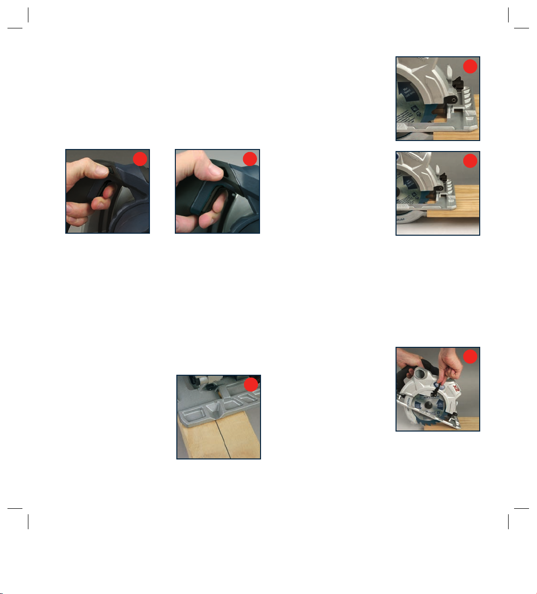
• Check lower guard for proper closing before each use.
Do not operate the saw if the lower guard does not move
freely and close instantly. Never clamp or tie the lower
guard in the open position. If the saw is accidentally
dropped, the lower guard may be bent. Raise the lower
guard with the guard retraction lever and make sure it
moves freely and does not touch the blade or any other
part, in all angles and depths of cut.
• Check the operation and condition of the lower guard
spring. If the guard and the spring are not operating
properly, they must be serviced before use. The lower
guard may operate sluggishly due to damaged parts,
gummy deposits, or a buildup of debris.
• The lower guard should be retracted manually only for
special cuts such as “Pocket Cuts” and “Compound
Cuts”. Raise the lower guard using the guard retraction
lever. As soon as the blade enters the material, the lower
guard must be released. For all other sawing tasks, the
lower guard should operate automatically.
• Always check that the lower guard is covering the blade
before placing the saw down on a bench or the floor. An
unprotected, coasting blade will cause the saw to walk
backwards, cutting whatever is in its path. Be aware of
the time it takes for the blade to stop after the switch is
released.
• NEVER hold the piece being cut in your hands or across
your leg. It is important to support the work properly to
minimize body exposure, blade binding, or loss of control.
• Hold the tool by the insulated gripping surfaces when
performing an operation where the cutting tool may
contact hidden wiring or its own cord. Contact with a “live”
wire will also make exposed metal parts of the tool “live”
and could cause an electric shock to the operator.
• When ripping, always use a rip fence or straight edge
guide. This improves the accuracy of cut and reduces
the chance of the blade binding.
• Always use blades of the correct size and shape
(diamond vs. round) arbour holes. Blades that do
not match the mounting hardware of the saw will run
eccentrically causing loss of control.
• Never use damaged or incorrect blade washers or
bolts. The blade washers and bolt were specially
designed for your saw, for optimum performance
and safety of operation.
Causes and operator prevention of kickback
Kickback is a sudden reaction to a pinched, bound or
misaligned saw blade, causing an uncontrolled saw to
lift up and out of the workpiece toward the operator.
When the blade is pinched or bound tightly by the kerf
closing down, the blade stalls and the motor reaction
drives the unit rapidly back toward the operator.
If the blade becomes twisted or misaligned in the cut, the
teeth at the back edge of the blade can dig into the top
surface of the wood causing the blade to climb out of the
kerf and jump back toward operator.
Kickback is the result of tool misuse and/or incorrect
operating procedures or conditions and can be avoided
by taking proper precautions as given below:
• Maintain a firm grip with both hands on the saw and
position your body and arm to allow you to resist kickback
forces. Kickback forces can be controlled by the operator,
if proper precautions are taken.
• When blade is binding, or when interrupting a cut for any
reason, release the trigger and hold the saw motionless
in the material until the blade comes to a complete
stop. Never attempt to remove the saw from the work
or pull the saw backward while the blade is in motion
or kickback may occur. Investigate and take corrective
actions to eliminate the cause of blade binding.
• When restarting a saw in the workpiece, center the saw
blade in the kerf and check that the saw teeth are not
engaged into the material. If the saw blade is binding,
it may jump up or kick back from the workpiece as the
saw is restarted.

7
• Support large panels to minimize the risk of blade
pinching and kickback. Large panels tend to sag under
their own weight. Supports must be placed under the
panel on both sides near the line of cut and near the
edge of the panel.
• Do not use dull or damaged blades. Unsharpened or
improperly set blades produce a narrow kerf causing
excessive friction, blade binding and kickback.
• Blade depth and bevel adjusting locking levers must
be tight and secure before making a cut. If the blade
adjustment shifts while cutting, it may cause binding
and kickback.
• Use extra caution when making a “Plunge Cut” into
existing walls or other blind areas. The protruding blade
may cut objects that can cause kickback.
• Do not use blades made of high-alloy, high-speed
steel (HSS).
• Do not use the circular saw near fumes or combustible
liquids.
• Secure small pieces of wood firmly before working.
Never hold them in your hand.
• Never slow the blade down with your hands or by
applying pressure to the side of the blade.
• Never apply force! Advance the circular saw gently
and steadily.
Extension cords
• Replace damaged cords immediately. Use of damaged
cords can shock, burn or electrocute.
• If an extension cord is necessary, a cord with adequate
size conductors should be used to prevent excessive
voltage drop, loss of power or overheating. The table
shows the correct size to use, depending on cord length
and nameplate amperage rating of tool. If in doubt, use
the next heavier gauge. Always use U.L. and CSA listed
extension cords.
Accessories
The 909 LS15CS Circular Saw is supplied with the following
accessories as standard:
1. Blade (fitted)
2. Blade wrench
3. Rip fence
Unpacking
Due to modern mass production techniques, it is unlikely
that your 909 Power Tool is faulty or that a part is missing.
If you find anything wrong, do not operate the tool until the
parts have been replaced or the fault has been rectified.
Failure to do so could result in serious personal injury.
Assembly
The 909 circular saw is packed, fully assembled except for
the rip fence.
RECOMMENDED SIZES OF EXTENSION CORDS
Tool’s
Ampere
rating
Volts Total length of cord in feet. Cord size
in A.W.G. (minimum)
25ft 50ft 100ft 150ft
3–6 120V~ 18 16 16 14
6–8 120V~ 18 16 14 12
8–10 120V~ 18 16 14 12
10–12 120V~ 16 16 14 12
12–16 120V~ 14 12 - -

8
Know your product
1. Dual Laser light
assembly
2. Dual Laser light on/off button
3. Dual Laser light aperture
4. Trigger switch
5. Lock-off button
6. Motor housing
7. Main handle
8. Front handle
9. Bevel adjustment knob
10. Bevel scale
11. Parallel fence locking knob
12. Parallel fence
13. Blade guard lever
14. Lower blade guard
15. Base plate
16. Upper blade guard
17. Dust extraction port
18. Depth locking lever
19. Depth of cut indicator
20. Spindle lock button
21. Blade
22. Blade wrench
23. Blade guide notch
24. Parallel fence slots
25. Disc rotation indicator
14
2
1
3
10
9
23
20
21
13
16
17
22
6
15
18
7
19
4
5
8
11
12
25
24

9
Overview
You have purchased a 15 Amp Magnesium Circular Saw
with the 909 laser line generator system.
Please refer to the safety instructions given earlier in this
manual for important instructions regarding the use of the laser.
The saw is capable of ripping and cross cutting hardwoods,
softwoods and man made boards quickly, accurately and safely.
By loosening the bevel adjustment knob (9), the body and
the blade of the saw can be tilted to any angle up to 55° for
making angle cuts. Please note that the maximum depth of
cut is reduced when cutting at an angle.
A fixed upper blade guard (16) encloses the upper part of
the blade. As the saw advances through the work piece,
the pivoting lower blade guard (14) is pushed back by the
edge of the wood to expose only that part of the blade
which is needed. When the blade clears the work, the
spring loaded lower blade guard snaps back to completely
enclose the blade.
Adjusting the cutting depth
CAUTION. Always ensure that the saw is switched off
and unplugged from the power supply before making
any adjustments.
1. Ensure that the saw is facing away from you.
2. Loosen the depth locking lever (18) (Fig. A).
3. Hold the base plate flat against the edge of the work
piece and lift the body of the saw until the blade is at the
right depth (Fig. B). Use the depth of cut indicator (19) to
determine the cutting depth.
4. Tighten the depth locking lever (18).
Note. Always use the correct blade depth setting.
The correct blade depth setting for all cuts should not be
more than 1/4” (6.35mm) below the material being cut.
Allowing more depth will increase the chance of kickback
and result in a rough cut.
Adjusting the bevel angle
CAUTION. Always ensure that the saw is switched off
and unplugged from the power supply before making
any adjustments.
1. The saw can be adjusted to cut at any angle between
0° and 55°. When making 45° bevel cuts, there is a
notch (23) in the saw base to help you line up the blade
with the line of cut. Align your line of cut with the inner
blade guide notch on the base of the saw when making
45° bevel cuts.
2. Loosen the bevel adjustment knob (9) located at the front
of the base plate (Fig. C).
3. Tilt the body of the saw until
the required angle is reached
(Fig. D) using the bevel scale
(10) as a guide.
4. Tighten the bevel adjustment
knob (9) to secure the base
plate (Fig. E).
B
A
D
C
E

10
Note. Always make a trial cut in a scrap piece of material
along a guideline to determine how much you should offset
the blade from the guideline to make an accurate cut.
Switching on and off
1. Connect the plug to the power supply.
2. Depress the lock-off button (5) (Fig. F) and squeeze the
trigger switch (4) (Fig. G).
3. The blade will take approximately 2 seconds to reach
full speed.
4. When you release the trigger, the machine turns off
and the lock-off button re-engages to prevent
accidental operation.
CAUTION. Ensure you have a firm grip on the handles with
both hands at start up as the tool will produce kickback.
Making a cut
1. Mark the line of cut on the work piece.
2. Adjust the depth of cut and bevel angle as required.
3. When making 90° cross or rip
cuts, align your line of cut with
the outer blade guide notch on
the base of the saw (Fig. H).
4. When making 45° bevel cuts,
align your line of cut with the
inner blade guide notch on the
base of the saw.
5. Rest the front edge of the base
on the work piece (Fig. I).
6. Start the motor by depressing
the lock-off button (5) and
squeezing the trigger
switch (4).
Note. Always let the blade reach
full speed (approximately
2 seconds) before you begin to
cut into the work piece.
7. Slowly push the saw forward
using both hands (Fig. J).
8. When making a cut always
use steady, even pressure.
Forcing the saw causes rough
cuts and could shorten the life
of the saw or cause kickback.
Allow the blade and the saw to
do the work.
9. After completing your cut, release the trigger switch
and allow the blade to come to a complete stop.
Do not remove the saw from the work piece while the
blade is moving.
Note. Since blade thickness varies, always make a trial
cut in scrap material along the guideline to determine how
much, if any, the guideline must be offset to get an
accurate cut.
Making a pocket cut
1. Adjust the depth of cut as
required.
2. Adjust the bevel setting to 0°.
3. Raise the lower blade guard
lever (13) to expose the saw
blade and firmly rest the
front of the base flat against
the work piece with the rear
handle raised so the blade does not
touch the work piece (Fig. K).
G
F
I
J
K
Blade guide
notch H
Blade guide notch

11
4. With the blade just clearing the work piece, start the
motor by depressing the lock-off button (5) and squeezing
the trigger switch (4).
5. Always let the blade reach full speed (approximately
2 seconds) before you begin to cut into the work piece.
6. Slowly lower the saw into the work piece, using the front
of the base resting on the work piece as a hinge point.
WARNING. As soon as the blade starts cutting the material,
release the lower blade guard lever.
7. Once the base plate (15) is flat against the work piece,
proceed cutting in a forward direction to the end of
the cut.
8. After completing your cut, release the trigger switch
and allow the blade to come to a complete stop.
Do not remove the saw from the work piece while the
blade is moving.
Note. If the corners of your pocket cut are not completely
cut through, use a jigsaw or hand saw to finish the corners.
Using the parallel fence
The parallel fence (12) allows you to make parallel cuts
in a sheet of wood, all at the same width.
CAUTION. Always ensure that the saw is switched off
and unplugged from the power supply before making
any adjustments.
1. Loosen the parallel fence locking knob (11) (Fig. L).
2. Slide the parallel fence (12) through the parallel fence
slots (24) in the base plate (15) (Fig. M).
3. Adjust the parallel fence to the
required width and secure it in
position with the parallel fence
locking knob (11).
4. Ensure that the parallel
fence rests against the
wood along its entire length
to give a consistent parallel
cut (Fig. N).
Using the dual laser system
The dual laser line is designed for guiding the tool along a
desired line of cut on a workpiece. The dual laser allows
you to choose whether waste material is on the inner or
outer side of the blade.
WARNING. Before proceeding to use the dual laser line
system, ensure that the Additional safety rules for laser
lights section is read and fully understood.
Always ensure the laser beam is aimed at a sturdy work
piece without reflective surfaces. i.e. wood or rough coated
surfaces are acceptable. Bright shiny reflective sheet steel
or the like is not suitable for laser use as the reflective
surface could direct the beam back at the operator.
Only turn laser beam on when tool is on work piece.
1. Mark the line of the cut on the work piece.
2. Adjust the depth of cut and bevel angle as required.
3. Rest the front edge of the base on the work piece.
4. Switch on the laser beam using the laser light on/off
button (2) (Fig. O).
5. Align the beam with the line on the work piece (Fig. P).
M
L
N
P
O

12
6. Start the motor by depressing the lock-off button (5) and
squeezing the trigger switch (4).
7. Always let the blade reach full speed (approximately
2 seconds) before you begin to cut into the work piece.
8. Slowly push the saw forward using both hands, keeping
the red laser light beam on the line of cut.
9. After completing your cut, release the trigger switch
and allow the blade to come to a complete stop.
Do not remove the saw from the work piece while
the blade is moving.
10. Switch off the laser beam on completion of the cut.
Note. The laser generated line is preset to align with the
left side of the blade (closest to the motor).
Changing the blade
CAUTION. Always ensure that the saw is switched off
and unplugged from the power supply before making any
adjustments.
1. Place saw on its side on a flat surface.
2. Rotate the saw blade by hand whilst depressing the
spindle lock button (20) until the blade locks (Fig. Q).
3. Whilst depressing the spindle lock button, turn the blade
bolt anti-clockwise using the wrench provided (Fig. R).
4. Remove the outer blade flange and the blade bolt.
5. Raise the lower blade guard (14) using the blade
guard lever (13).
6. Remove the saw blade
from the inner flange
and pull it out (Fig. S)
7. Clean the saw blade
flanges thoroughly
before mounting the new
saw blade. Wipe a drop
of oil onto the inner and
outer flange where they
will touch the blade.
8. Mount the new saw blade onto
the spindle and against the
inner flange.
9. Replace the outer flange and
tighten the blade bolt (Fig. T).
WARNING. The direction in
which the blade rotates has
to be the same as the direction
of the arrow marked on the housing (25).
10. Ensure that the spindle lock button (20) is released.
11. Before using the saw again, check that the safety
devices are in good working order.
IMPORTANT. After replacing the saw blade, make sure that
the saw blade runs freely by turning the blade by hand.
12. Plug the machine into a power socket and run the saw
under no load to check that it runs smoothly before
using it to cut any material.
Adjusting the twin laser
IMPORTANT. The tool should be plugged into a power
source when checking and adjusting the dual laser line.
Ensure hands are kept well away
from the saw blade and avoid
accidental activation of the trigger.
1. To adjust the twin laser, insert
a hex key into the laser guard
and turn to move the laser
from side to side. This will
align the laser with the blade
(Fig. U).
R
Q
S
T
U

13
Maintenance
WARNING. Always ensure that the tool is switched off and
the plug is removed from the power point before making any
adjustments or maintenance procedures.
Cleaning
1. Keep the tool’s air vents unclogged and clean at all times.
2. Remove dust and dirt regularly. Cleaning is best done
with a rag.
3. Re-lubricate all moving parts at regular intervals.
4. If the body of the saw needs cleaning, wipe it with a soft
damp cloth. A mild detergent can be used but nothing like
alcohol, petrol or other cleaning agent.
5. Never use caustic agents to clean plastic parts.
CAUTION. Do not use cleaning agents to clean the plastic
parts of the tool. A mild detergent on a damp cloth is
recommended. Water must never come into contact
with the tool.
General inspection
Regularly check that all the fixing screws are tight. They
may vibrate loose over time.
Power cord maintenance
If the supply cord needs replacing, the task must be carried
out by the manufacturer, the manufacturer’s agent, or a
qualified electrical service repairer to avoid a safety hazard.
Troubleshooting
Trouble Problem Suggested remedy
Saw will not start Power cord not plugged in Ensure that the cord is connected to the power supply
Power fault, fuse or circuit breaker tripped Check the power supply
Cord damaged Use qualified power tool service agent to repair or replace
Burned out switch Use qualified power tool service agent to repair or replace
Faulty motor Use qualified power tool service agent to repair or replace
the motor
Blade does not reach
full speed
Tool is overheating Turn off the tool and let it cool down to room temperature.
Inspect and clean the ventilation slots
Poor cutting Blunt blade Replace or sharpen circular saw blade
Vibration or abnormal
noise
Loose parts Check to see that all knobs and levers are securely
tightened including bevel adjustment knob, depth locking
lever and parallel fence locking knob
Blade vibrating Ensure that the blade nut is securely tightened
Moving parts excessively worn Use a qualified electrical service repairer to repair or replace

14

15

Table of contents
Other 909 Saw manuals