manuals.online logo
Brands
  1. Home
  2. •
  3. Brands
  4. •
  5. A/DA
  6. •
  7. Amplifier
  8. •
  9. A/DA Suite 7.1 Quick start guide

A/DA Suite 7.1 Quick start guide

ELAN Home Systems ●1690 Corporate Circle ●Petaluma, CA 94954 USA
tech support: 800.622.3526 • main: 760.710.0990 • sales: 877.289.3526 • email: [email protected]
©2013 ELAN Home Systems. All rights reserved. ELAN and g! are trademarks of ELAN Home Systems. All other trademarks are the property of their respective owners.
Integration Note
Manufacturer: ADA
Model Number(s): Suite 7.1
Core Module Version:
Comments: Firmware: Release 4.15, Prom v1.70g, DSP 2.1.5201
Document Revision Date: 1/10/2013
OVERVIEW AND SUPPORTED FEATURES
The Suite 7.1 surround sound preamplifier provides an RS-232 connection through the ISO-CAT II or
ISO-232 isolation box. This serial connection to the g! system provides full two-way communications,
enabling reliable control as well as providing feedback to the g! system when changes (such as the
current source or volume levels) occur at the receiver.
THESE PREAMPS SUPPORT THE FOLLOWING FEATURES:
Basic Source and Volume Control: Select any available source and control volume with two-way
feedback. Changes made at the preamp (turning the volume control, changing source) are immediately
reflected in the g! interface.
Surround Mode Control: Change the surround mode from the g! interface.
THESE PREAMPS DO NOT SUPPORT THE FOLLOWING FEATURES:
Any feature not specifically noted as supported should be assumed to be unsupported.
INSTALLATION OVERVIEW
1. During the rough-in phase install the necessary speaker and video cabling for the theater installation.
2. Also during the rough-in phase, run a Cat5 wire from the location of the preamp and isolation box
back to the Network Assembly of the g! system to provide the serial connection needed to control the
preamp. Refer to the RS-232 Connection Options Integration Note for other serial connection
options.
3. Install the speakers, display and other theater components.
4. Program the preamp according to the manufacturer’s documentation: see ADA Programming below.
5. Test the theater to ensure that the sources play correctly and that the audio and video operate as
expected.
6. Connect the g! system to the preamp electrically. See the connection diagram for more information.
7. Configure the g! system for the preamp and confirm communication between the preamp and the g!
system controller.
8. Test the system by changing sources and volume to confirm the correct source plays.
2 of 5
ADAPROGRAMMING
The ADA must be programmed according to normal ADA instructions, with the following additional
requirements:
SWITCH SETTINGS ON ISOLATION BOX
The isolation box has switches which must be set as follows:
1. Set switches 1, 2 and 3 Down
2. Switch 4 Up.
SET THE BUS ADDRESS TO 0
The ADA preamp must currently be set with a bus address of 0. This can be done using the front panel
menu, or using the ADA setup software. Perform the following steps to set the bus address at the front
panel (see the ADA documentation for more information):
1. Press and hold the Mode knob until display changes to Tone, Balance, … recall.
2. Rotate Mode knob until cursor is over P in PRO SETUP.
3. Press Mode knob: display should change to Pro Setup menu.
4. Rotate Mode knob until cursor is over A in ADABUS.
5. Press Mode knob: display should change to ADA bus menu, with cursor over B in BUS ADDRESS.
6. Rotate knob to change bus address to 0.
SET THE BAUD RATE TO 19200
Perform the following steps to set the baud rate at the front panel:
1. Press and hold the Mode knob until display changes to Tone, Balance, … recall.
2. Rotate Mode knob until cursor is over P in PRO SETUP.
3. Press Mode knob: display should change to Pro Setup menu.
4. Rotate Mode knob until cursor is over A in ADABUS.
5. Press Mode knob: display should change to ADA bus menu, with cursor over B in BUS BAUD.
6. Rotate knob to change baud to 19200.
SET LOGICAL INPUT NAMES
The g! system will read the input names programmed into the ADA. Use the Suite 7.1 Tester program to
program the names. Choose the Defaults tab along the left side, and the Suite 7.1 Download tab on the
top to find the Logical Inputs configuration page.
3 of 5
CONNECTION DIAGRAMS
4
2
g! System
Controller
DM9M to RJ45 Adapter
RS-232
ADA Preamp
Amplifier
Other Sources
3Cat5 Cable Assy
ADA Bus
ADA Bus
ISO-CAT II or
ISO-232
1ADA RS-232 Isolation Box
RS-232
BILL OF MATERIALS
# Device Manufacturer Part Number Protocol Connector Type Notes
1 IsolationBox ADA ISO-CAT IIor ISO-232 ADA Bus XRS-232 ADA Bus XDB-9Female
2 DB9M to RJ45Adapter ELAN HA-CB-307 RS-232 DB-9 Male X RJ-45Female
3 Cat5 Cable A ssy. Installer N/A RS-232 RJ-45 M ale X Wire
4 g! Co ntro ller ELAN Various (e.g. HC12) RS-232 DB9 M ale / USB
4 of 5
G!CONFIGURATION DETAILS
The following table provides settings used in the g! Configurator. Please refer to the g! Configurator Reference Guide for more details.
o“<Select>” Select the appropriate item from the list (or drop-down) in the Configurator.
o“<User Defined>”, etc. Type in the desired name for the item.
Devices Variable Name Setting Comments
Communication Devices Name <User Defined> (Default: Receive
r
)
Type Serial Port Refer to the RS-232 Connection Option Integration note for alternative configurations
Communication Type <Select> Select the Communication Type that matches your receiver, if no comapatible type is listed then select Standard Connection
Location <User Defined> (Not Required)
COM Port <Select>
Audio Tuners (Optional) Name <User Defined> (Default:
A
M/FM Tune
r
)Optional: Only needed if the tuner will be a visible source in the Viewer interface
Device Type <Select> Select the tuner that matches your receiver
Location <User Defined> (Not Required)
COM Device <Select> (Default: Receive
r
)
<Other RS-232 Sources>
<Other IR Controlled Sources>
<Video Display> Add the Video Display for the receiver. Refer to the Integration Note for the specific display, or the Generic Video Displa
y
Integration Note for an IR controlled display
Other Audio Devices / Interfaces Name <User Defined> Add one Interface for each source that should appear in the Viewer
Template <Select>
Default Device <Select> Select the RS-232 or IR controlled source for this interface
Audio Zone Controllers Name <User Defined> Defaults to the make and model of your receiver, after selecting Device Type
Device Type <Select> Select your model of receiver
Location <User Defined> (Not Required)
COM Device <Select> (Default: Receive
r
)
Sources Name <User Defined>
Source Device <Select> Sources must be previously configured in order to allow selection.
Source Icon <Select> This icon appears on the source button in the Viewer Interface
Display Name <User Defined> This text appears on the source button in the Viewer Interface
Zones Name <User Defined>
Display <Select> Select the Video Display in this zone
Universal Receiver <Select> Refer to the HomeLogic Universal Remote Integration Note for more details
<Source>
Display On/Off <Select> For each source, select what the display should do when that source is active
Display Source <Select> If using more than one input on the video display select the input for each source.
Show Source <Select> Set to No for any inputs on the receiver that are not used or do not want to be seen in the zone
<Interface Tab> Click on the Interface tab in order to hide or show zone tabs on indivdual touchscreens
<Touchscreen Options> Select the touchscreen to modify from the list
Tab Layouts <Select> Move any unused zone tabs into Available Zones to remove from the viewer
Add any other RS-232 controlled sources. Refer to the Integration Note for each specific source device.
Add IR devices on the Input/Output tab for other IR controlled sources. Refer to the Generic IR Source Integration note.
5 of 5
COMMON MISTAKES

Other A/DA Amplifier manuals

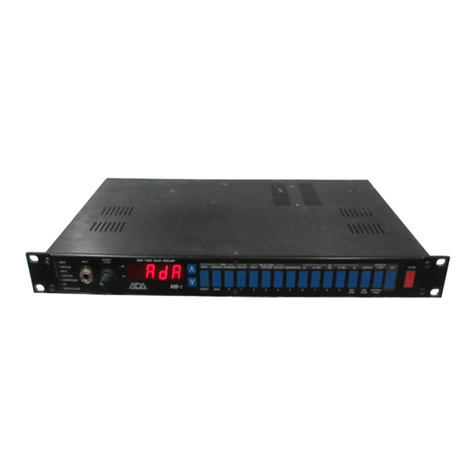
A/DA MB-1 User manual

A/DA

A/DA MB-1 User manual

A/DA MP-1 User manual

A/DA

A/DA MP-1 User manual

A/DA APP-1 User manual

A/DA

A/DA APP-1 User manual

A/DA MP-1 User manual

A/DA

A/DA MP-1 User manual

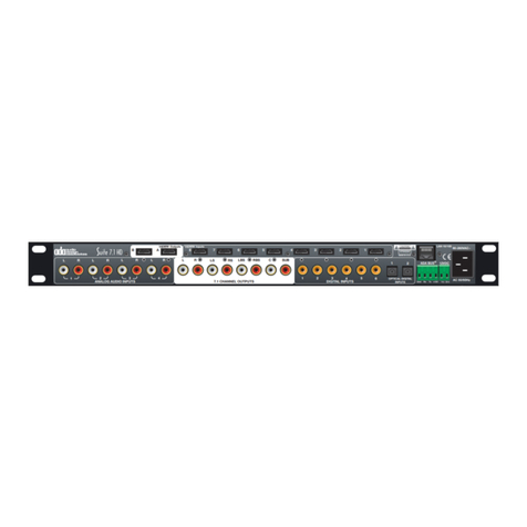
A/DA Suite 7.1 HD User manual

A/DA

A/DA Suite 7.1 HD User manual

A/DA Microcab II User manual

A/DA

A/DA Microcab II User manual

A/DA T100S User manual

A/DA

A/DA T100S User manual

A/DA SSD-66 User manual

A/DA

A/DA SSD-66 User manual

A/DA MP-2 User manual

A/DA

A/DA MP-2 User manual

A/DA MP-1-CHANNEL User manual

A/DA

A/DA MP-1-CHANNEL User manual

A/DA Cinema Rhapsody Mach II User manual

A/DA

A/DA Cinema Rhapsody Mach II User manual

A/DA MP-1 User manual

A/DA

A/DA MP-1 User manual

A/DA MP-1 User manual

A/DA

A/DA MP-1 User manual

A/DA PTM-6150 User manual

A/DA

A/DA PTM-6150 User manual

A/DA Cinema Rhapsody User manual

A/DA

A/DA Cinema Rhapsody User manual

Popular Amplifier manuals by other brands

Yamaha M-70 owner's manual

Yamaha

Yamaha M-70 owner's manual

AMC MIC iMIX user manual

AMC

AMC MIC iMIX user manual

AR 750S1G6C Operating and service manual

AR

AR 750S1G6C Operating and service manual

AMTC EQ-AMP4X6 instruction manual

AMTC

AMTC EQ-AMP4X6 instruction manual

Denon PMA-500AE operating instructions

Denon

Denon PMA-500AE operating instructions

Magnatone SUPERFIFTYNINE M-80 manual

Magnatone

Magnatone SUPERFIFTYNINE M-80 manual

SAE 8300 Operator's manual

SAE

SAE 8300 Operator's manual

RCF ES3323 quick guide

RCF

RCF ES3323 quick guide

Jensen JAHD240BT owner's manual

Jensen

Jensen JAHD240BT owner's manual

PCB Piezotronics HT426E01 Installation and operating manual

PCB Piezotronics

PCB Piezotronics HT426E01 Installation and operating manual

Xtant xtant1.1i Specification sheet

Xtant

Xtant xtant1.1i Specification sheet

Trinity Amps Triton Builder's guide

Trinity Amps

Trinity Amps Triton Builder's guide

Sierra Wireless AirBooster 350 user guide

Sierra Wireless

Sierra Wireless AirBooster 350 user guide

Fender '57 Custom Twin-Amp owner's manual

Fender

Fender '57 Custom Twin-Amp owner's manual

Gefen HDMI-CAT5-144 user manual

Gefen

Gefen HDMI-CAT5-144 user manual

Audio Research Reference 5 owner's manual

Audio Research

Audio Research Reference 5 owner's manual

Down4Sound JP33 owner's manual

Down4Sound

Down4Sound JP33 owner's manual

ELECTROCOMPANIET AW 800 M owner's manual

ELECTROCOMPANIET

ELECTROCOMPANIET AW 800 M owner's manual

manuals.online logo
manuals.online logoBrands
  • About & Mission
  • Contact us
  • Privacy Policy
  • Terms and Conditions

Copyright 2025 Manuals.Online. All Rights Reserved.