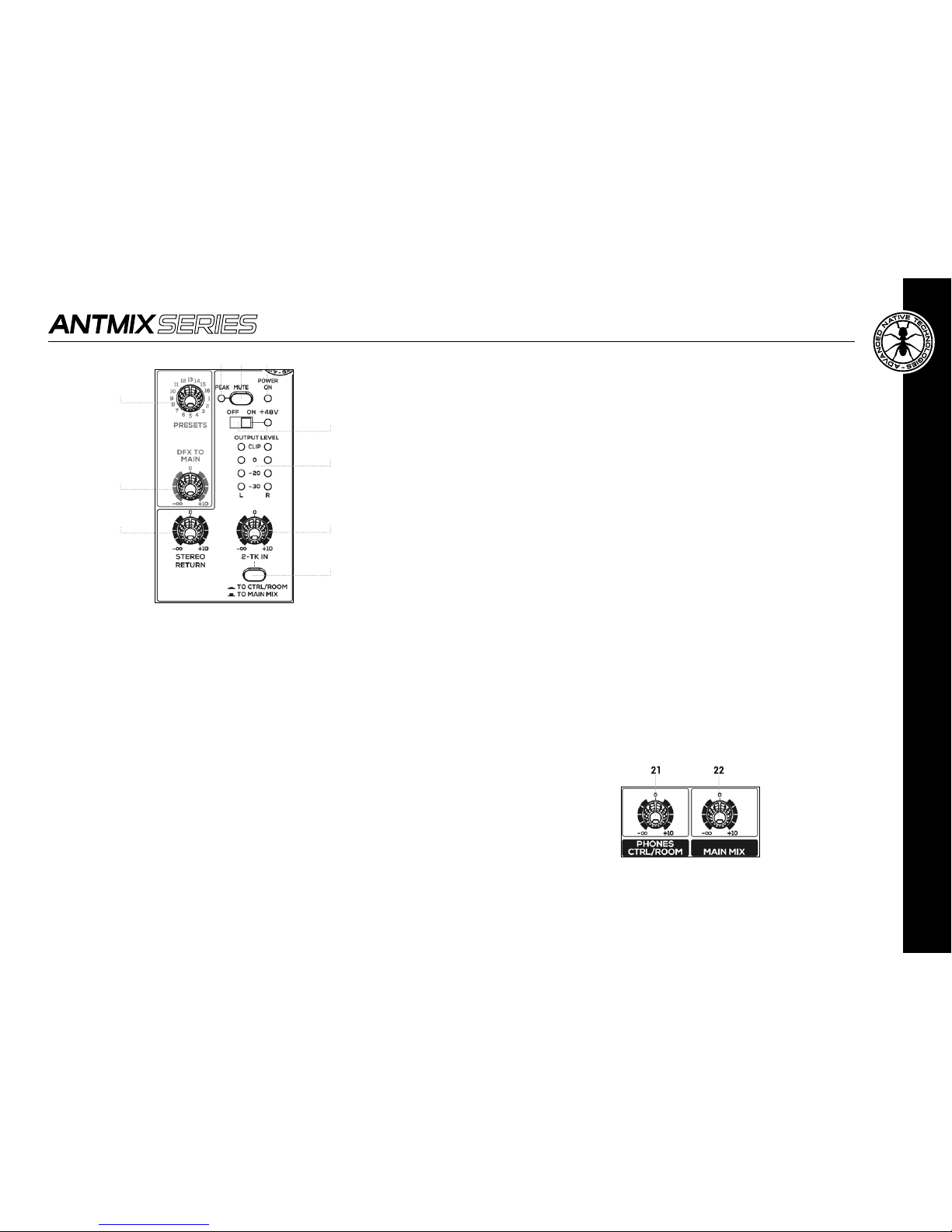
11 DFX DISPLAY
This display shows the numbers corresponding to selected
effects by the PROGRAM (PUSH) encoder.
12 PROGRAM
This 100 position selector allows you to choose the type
of effect.
Turnthe knob untilyou reachthe desiredprogram,then press
the knob to activate the selected effect.
The rst 10 programs called ECHO reproduce the classic echo
effectwithincreasingdelay inthesubsequent variants,ECHO
+VERB algorithmsemulatea combinationofecho andreverb,
the impressive effect used in many musical productions, the
TREMOLO effects are mostly used on stringed instruments,
whilePLATE,CHORUS, andVOCALprograms offerapleasant
sound widening and are ideal to strengthen vocals.
The ROTARY effects simulate leslie organ, while the SMALL
ROOM programs reproduce the reverberation of rooms with
similar dimensions to those of residential rooms, alternating
thesimulationofreflectiveandabsorbentwalls.TheFLANGER
+ REV section represents a combination of effects perfect
for different instruments, in particular keyboards, and nally
the LARGE HALL effects package simulate the reverberation
of environments with large volumes characterized by mostly
reflecting, naked walls.
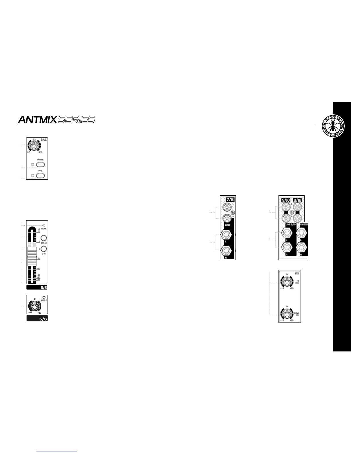
13 PEAK/MUTE
This LED is lit when the signal sent to DFX is too high, and
there's a risk to saturate the internal effect. It's a good setting
of the effect sends when the LED flashes occasionally, only on
signal peaks. When the LED remains continuously lit, it is an
indication of saturation. In that case please cut the volume of
DFX POST channel sends.
14 DFX MUTE
This button allows you to enable or disable the return signal of
the internal effects unit.
15 DFX RETURN
This fader sets the signal level of the internal effects
unit to the main output.
Use it to increase or decrease the amount of
processed signal to be sent to the MAIN MIX.
16 +48V – BUTTON AND LED
This two-position switch allows you to turn on or
off the phantom power for condenser microphones:
ON = Switch pressed, LED lit.
OFF = Switch raised, LED turned off.
WARNING: To prevent loud noises to your sound
system, activate the phantom power only after
lowering the levels of the channels and connecting
the microphones.
17 STEREO RETURN
This knob sets the signal level of external stereo
effects unit to the main output.
Use it to increase or decrease the amount of
processed signal to be sent to the MAIN MIX.
18 2-TK IN
This knob sets the level of 2-TRACK IN input signal.
19 TO CTRL/ROOM - TO MAIN MIX
Press this switch to assign 2-TRACK IN input signal
to CTRL/ROOM or to MAIN MIX outputs.
20 POWER ON