Soundking DX20 User manual


1
Introductions................................................................................................................................ 2
Features....................................................................................................................................... 2
3
Output Channel 6
Mic Channel 6
Input Stage Subpage 7
EQ Subpage 8
Dynamics Subpage 9
Bus Send Subpage. 11
Output Stage Subpage 12
Stereo and DCA Channel 13
BUS Page 15
Input Stage Subpage 15
Output Stage Subpage 17
Setup Page 18
Routing Page 19
Meter Page 21
FX Page 21
Modulation Subpage 22
Delay Subpage 23
Reverb Subpage 25
GEQ Subpage 27
Scenes Page 28
Media Page 29
Monitor Page 30
Custom Page 31
Customizing Shortcut Keys Subpage 31
Customizing Layers Subpage 31
Group Mute Subpage 32
Dimension Drawing Page 33
Signal Flow Diagram 34
Technical Parameters 35
Console Software Upgrade Introductions 36
WIFI Connection Introductions 37
USB2.0 Expansion Card Instructions 39
..
.
Panel ............................................................................................................................................
Rear Panel ....................................................................................................................................5
..............................................................................................................................
...................................................................................................................................
......................................................................................................................
..................................................................................................................................
........................................................................................................................
.......................................................................................................................
..................................................................................................................
...............................................................................................................
.....................................................................................................................................
.....................................................................................................................
..................................................................................................................
...................................................................................................................................
................................................................................................................................
....................................................................................................................................
........................................................................................................................................
......................................................................................................................
..............................................................................................................................
............................................................................................................................
................................................................................................................................
..................................................................................................................................
...................................................................................................................................
.................................................................................................................................
.................................................................................................................................
..............................................................................................
.........................................................................................................
.....................................................................................................................
...............................................................................................................
......................................................................................................................
....................................................................................................................
........................................................................................
.......................................................................................................
..............................................................................................
Catalogue

2
Introductions
Soundking enters the digital mixing console market with a full featured compact digital mixing console
that combines the advantages of high-end hardware/touch slide control and 485 operation. It features
fourth-generation 40-bit SHARC floating-point processor, 24-bit/192kHz A/D and D/A conversion, 8 built-in
effects with reverb, delay, modulation and GEQ, 20 inputs including 12 professional MIC inputs and 4
COMBO inputs and professional digital signal inputs, 16 buses including 8 custom analog and digital
outputs, 4 multi-function custom buttons, 6 DCAs, 2 mute groups and 2 user-definable layers. Two USB
ports are installed for playback, recording and scene storage. Equipped with a 7’’ HD IPS touch screen,
the console has quick and intuitive operation, and is very suitable for all kinds of performances,
conferences, schools, intelligent buildings, industrial and mining enterprises, and personal use.
Features
12 Mic inputs, 4 COMBO inputs
1 S/PDIF inputs/outputs and AES/EBU outputs
16 buses 4 Mono output buses, 5 Stereo output buses, 1 Stereo monitor bus
8 custom assignable XLR output ports
4 multi-function custom buttons
6 DCA
2 mute groups
2 user-defined layers
1 pair of Stereo monitor outputs and 1 headphone outputs
1 7'' 1024×600 IPS touchscreen
IPS touchscreen with adjustable angle
8 internal effect modules
2 USB ports with stereo recording/playback/system update/scene import and export
Support scene memory
Support 485 control
S
PE AK
SIG
PE AK
SIG
PEA K
SIG
PEA K
SIG
PEA K PEAK
SIG
PE AK
SIG
PE AK
SIG
IN ST
DCA
IN
9-16
IN
1-8
SENDS
USER2
VIEW
USER1
BUS
PASTE
SEL
SOLO
MUTE
COPY
M.G1
M.G2
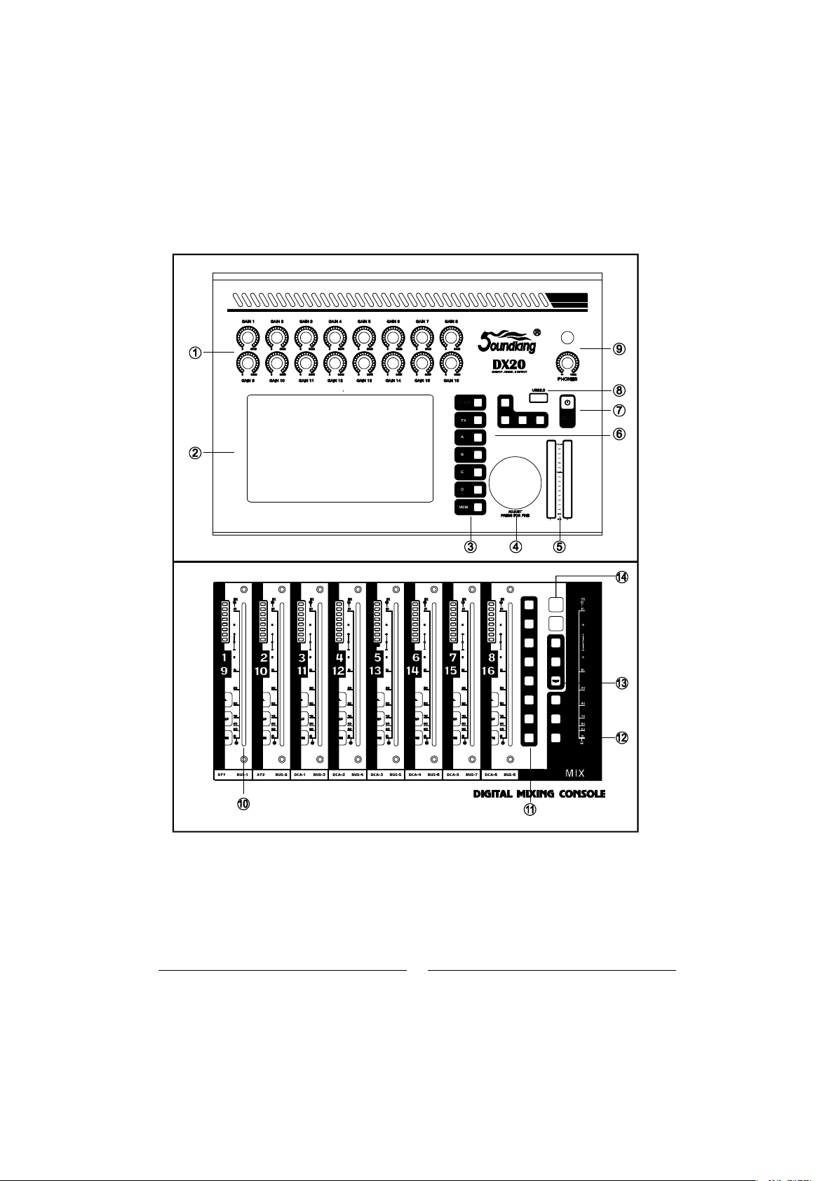
3
PANEL

4
1. Gain knob: Adjusts the gain of the corresponding input channel in the range 0-60dB
2 Screen Edit and control the mixer via the touch screen
3 Function key
Setup system function
FX effect
A, B C D self-defined function
VIEW
4 Adjust parameter knob: Operates with a touch screen to adjust parameters
5 16 level meter display main output level.
6 Play key Control MP3 playback pause previous next and recording
7 Power supply button.
8 USB2 0 You can insert a U-disk to play songs import and export scenes etc
9 Headphone Headphone output connector and volume control knob
10 Channel fader with SEL SOLO MUTE 8 level meter and motorized fader.
11 Layer control key
SENDS fast send
IN1-8 channel 1 to 8
IN9 16 channel 9 to 16
IN ST DCA stereo input and DCA group
BUS bus channel
USER1 USER2 user defined
12 Master channel fader: with SEL, SOLO MUTE and motorized fader
13 Mute group key.
14. Copy and paste button: Copy between channels, quickly copy the parameters
of one channel to another.
.
.
.
.
. .
. .
, -
. .
.
. :
.
, ,
.
. :
. : , , ,
.
. : , ,
:
. : , , ,
.
,

5
2
1
3 4 5 6 7 8 9
1. Outputs 1-8: 8 XLR output interface for analog signals to external devices
via XLR connection cables. Outputs 7-8 output the master channel signal
by default.
2. Input 1-16: 16 input interface for connecting a line or microphone to an
audio signal source.
3. USB2.0: same function as front panel USB interface.
4. Power supply: input 24V DC power supply interface.
5. Monitor: output stereo monitor signal.
6. AES/EBU: AES/EBU digital signal output via XLR cable.
7. S/PDIF: S/PDIF digital input and output.
8. RS-485: External control of the mixer via RS-485 protocol.
9. Expansion slot: Multi-track recording card interface.

6
2
3
4
5
①
②
③
④
⑤
Input Channel
DX20 has 12-channel mono inputs, 2 analogue stereo inputs, 1 stereo S/PDIF input channel and 1 stereo
USB input. INPUT 1-8 and INPUT 9-12 ST-USB buttons are for input page up/page down. INPUT 1-8 covers 8
channels MONO input channel CH1~CH8, INPUT 9-12 ST-USB covers 4 mono inputs (CH9~CH12), 2 analogue
stereo input channels, 1 stereo S/PDIF input and 1 stereo USB input. Press NPUT1-8 and INPUT9-12 ST-USB
page button, or slide left/right to flip pages.
MIC Channel
MIC input channels possess five individual modules, which are Input Stage, EQ, Dynamics, Bus Send and
Output Stage. With single press any module, the sub-page will pop up and you could shut it down if you press
the “close” button.
Input Stage
EQ
Dynamics
Bus Send
Output Stage
This module indicates settings of 48V phantom power, phase, delay, HPF and effects insert on the channel
This module indicates EQ curves on the channel
This module indicates Dynamics curves on the channel
This module indicates status of sending inputs to Busses, including the bus being sent and its level and
Pan value.
This module displays Mic input channel's name, Pan value, Solo, Mute, fader level setting and level
meter information. Single press , channel name and color can be edited, and you could specify
channel name and color with the soft keyboard popped up at the same time. the
7
2
3
4 5
6
7
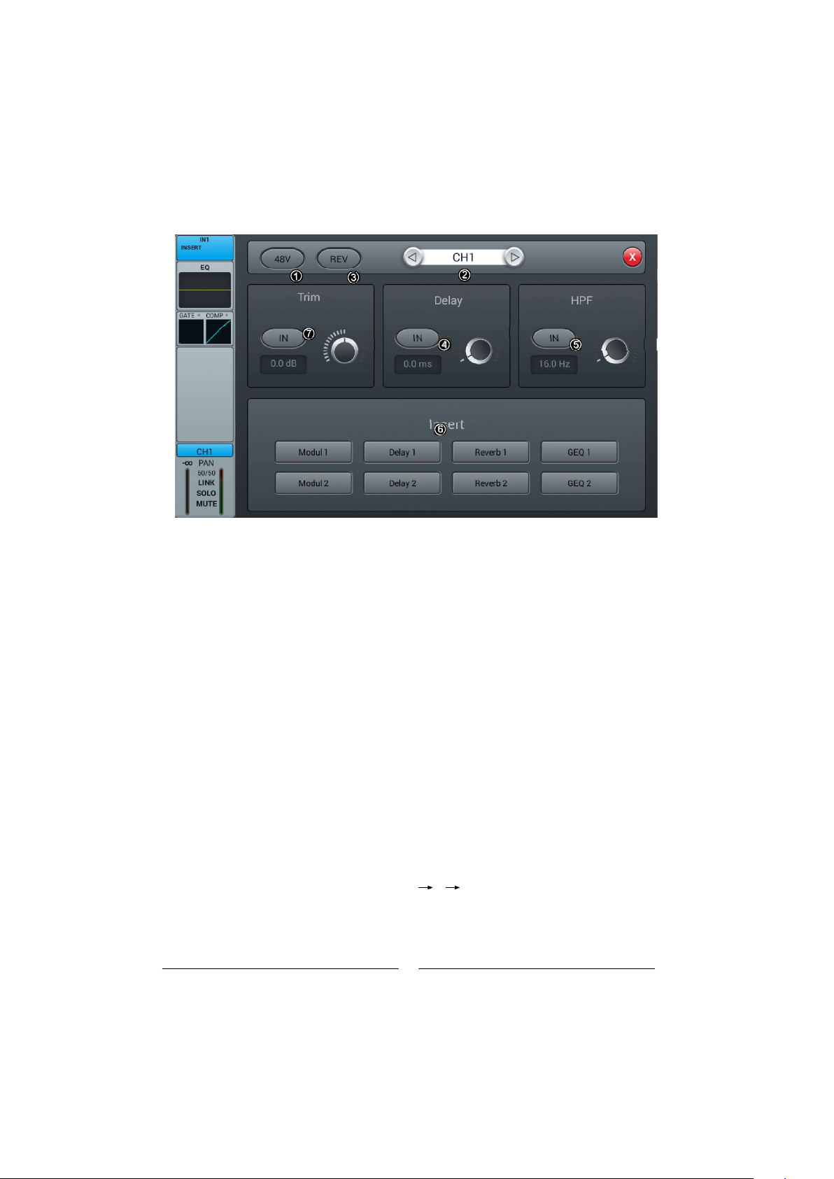
Input Stage subpage
①48V phantom power
Press the key, to enable the 48V phantom power. Press again to disable it. The default is set as disabled.
Switch channels
Press the key, to choose previous or next channel within a same layer
REV
Press the key to enable reverse. Press again to disable it. The default is set as disabled.
Delay
Press to enable the delay, and the default is set as disabled. To adjust the time of delay by turning the main
Encoder on the control panel or on the touch screen (fine tuning can be activated when pressed the knob down).
The delay ranges from 0ms to 200ms, while the default is 0ms.
HPF
Press to enable the HPF, and the default is set as disabled. To adjust the frequency of HPF by turning the
main Encoder on the control panel or on the touch screen (fine tuning can be activated when pressed the
knob down).The frequency ranges from 16 Hz to 400 Hz, while the default is 16 Hz.
Insert
Press the key of any effect module, to insert this module before the EQ on the channel. All effects cannot be
used on more than one channel, and all inputs can only be inserted with one effect module (the link parameter
of this module is the serial number of the channel). The busses (Bus1~Bus8, L&R) can be inserted with two
effect modules at the same time, which is sequenced to insert into the bus by the priority of selection. When
the selected module is occupied by other channel or bus, you will see a window popped up and say: “The
module can be used only once and it is already used by . Are you sure you want to use the module forcibly
now Yes No”. Access path of effect setting: SETUP FX double press to select the module “
②
③
④
⑤
⑥
⑦ Trim
Click the button to open it, which is closed by default. Adjust through the touch knob or the knob on the
panel (normal rotation of the knob is coarse adjustment, press and rotate to fine adjustment). The range
is -20 to 20dB, with a default value of 0dB.

8
EQ Sub Page
①
②
③
④
⑤
⑥
Switch Channels
Single press the key to switch between previous or next channel on the same layer
Bypass
Single press the key to enable Bypass, i.e. bypassed the EQ, press again to bring the EQ back. The default
is set as disabled.
Flat
Single press the key to flat the curves in EQ graph. The default is set as disabled.
4-band EQ graph
There are four points on the curve stand for the key frequencies (each ranges from 20Hz to 20KHz) of four
brands EQ filters, which you could drag, in order to set parameters of 4-band EQ filters. There is a floating
frame shows the parameter (gain, key frequency and Q value) of this filter when you selected a certain point
on the curve.
Select Key of 4-band EQ filter
Single press the key of a certain frequency range, to select the filter for it.
Parameter Settings
To adjust Gain, Frequency or Q value with the touch knob or the knob on the control panel (general tuning
by normally turning the main Encoder, press down the knob to access to the fine tuning)
Gain: to allow 18dB reduction or increase within the selected frequency range, default as 0dB.
Frequency:
Q: adjust the bandwidth of 4-band filters in the EQ, ranges from 0.5(wide) to 10.0(narrow),default as 0.5.
Band up/Band Dwn can switch between 4 frequencies; Low shelf/High Shelf can switch 1
and 4 to Shelf mode.

2
3
5
4
6
⑦ Library
Save or load user's EQ settings. Single press the dropdown button and select a library file from a popped-up
list, in order to load the EQ setting. Single press the ave button after you have done with EQ settings,“S ”
then select the library file (there are 16 names of library, Preset 1~Preset16) from the popped-up list. You
could simply edit the name of library with a popped-up keyboard and press confirm or ancel to save it “ ” “c ”
or not.
①
②
③
Dynamics sub-page
The sub-page includes channel selection, library, Gate, Compressor, Side Chain, etc.
Switch Channels
Single press the key to switch between previous or next channel on the same layer.
Side chain
press dropdown button, and select Side chain channel (CH1~CH12 ) in the list (CH1~CH12 ST1 ST2) .
Side Chain can select Pre/Post Eq of other single channel.
Gate
IN: Single press the key to enable Gate, press again to disable it. The default is set as disabled.
Gate curve: Y-axis indicates the Threshold, X-axis indicates time factor. Up curve is determined by Attack,
horizontal curve is determined by Hold, down curve is determined by Release.
Parameter Adjustment: To adjust the parameter of Gate by dragging the slider, or turning the main Encoder
on the control panel (fine tuning can be activated when pressed the knob down). Double press the parameter
frame to set it as default.
Threshold: Adjust the threshold of noise gate on the channel, ranges from -80 dB to 0 dB with default @ -80dB.
Any signal lower than Threshold will be cut off, as a result, the level of the signal has to surpass the threshold
in order to get through the noise gate.
Hold (time of hold): from 2 ms up to 2000 ms with default @ 2 ms.
Attack (time of start): from 0.5 ms to 100 ms with default @ 3 ms.
Release (time of release): from 2 ms to 2 s with default @350 ms (compatible with many kinds of sound source).
Depth: adjust attenuation of signals lower than the Threshold, ranges from 0 dB to -80 dB with default @-80 dB.
9

10
Compressor
IN: Press the key to enable Compressor, press again to disable it. The default is set as disabled.
Compressor: Threshold modifies breakpoint's position on the curve, Ratio modifies the bending rate of
the curve above the breakpoint, Gain controls the vertical position of the diagonal.
Parameter Adjustment: To adjust the parameter of Gate by dragging the slider, or turning the main Encoder
on the control panel (fine tuning can be activated when pressed the knob down).
Threshold: Adjust the Threshold of the compressor on the channel ranges from -80 dB to 0 dB with default
@ -20 dB. Any signal lower than Threshold will not be compressed. To decrease the level of the signal higher
than Threshold to a certain extent.
Ratio: Adjust compression ratio, from 1.0 to 20.0 with default @1.0.
Attack: from 0.5 ms to 100 ms with default @25 ms.
Release: from 20 ms to 5 s with default @350 ms (compatible with many kinds of sound source)
Gain: To compensate the compression, from -12 dB to +12 dB with default @0 dB.
Library
save or load the user Dynamics setting. Single press the button to display the library list to select one document.
It loads the Dynamics setting. After setting the Dynamics parameters, single press Save button to display library
list (16 library names, Preset 1~Preset 16 and select one document. This document is in the status of being
edited. Change the library name via the displayed keyboard, then click Confirm to confirm the saving. If you
do not want to change the library name, click Cancel.
Bypass
Single press the key to enable Bypass, to bypass Dynamics (Gate & Compressor), press again to disable
Bypass meanwhile enable Dynamics. The default is set as disabled.
④
⑤
⑥

11
2
3
4
5
Bus Send Sub-page
The input channel can send signal into 4-channel mono bus, 4-channel stereo bus and L/R master output bus.
①
②
③
④
⑤
Channel Switch
Bus-send enable
PreFader/PostFader Switch
PAN control
Send level control
Single press the key to switch between previous or next channel on the same layer.
Single press a bus button, to send signal to this bus, press again to disable the send.
The default is set as PreFader, single press the key to switch to PostFader, press again to set it
to default.
he default is set as 50|50, the PAN value can be tuned by dragging the slider, or turning the main
Encoder on the control pane. Double press the parameter frame to set it back to default.
Control the level of signal by drag the slider up and down.
back

12
2
456 7
3
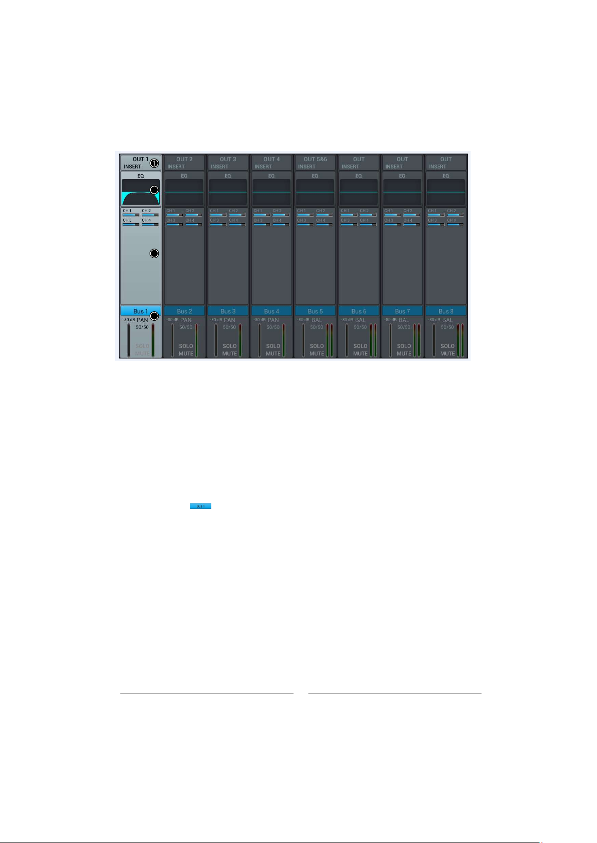
Output Stage Sub-page
The sub-page mainly contains PAN, Solo, Mute, fader control and signal level display.
①
Swtich Channel
Single press the key to switch between previous or next channel on the same layer.
②
PAN control
The default is set as 50|50, the PAN value can be tuned by touch knob, or physical knob on the control panel.
Double press the parameter frame to set it back to default.
③
④
Solo
Single press the key to enable monitor, press again to disable it. The default is set as disabled.
⑤
Mute
Single press the key to enable mute, press again to disable it. The default is set as disabled.
⑥
Fader control
Control the volume of fader level by dragging the slider, or faders on the control panel, the parameter frame
real-timely displays the value of fader level. Double press the parameter frame to fast set it back to 0.
⑦
Meter level display
The level meter of channel signal, indicating post-fader signal level of the channel.
Link
Single channel can be used as stereo channel.
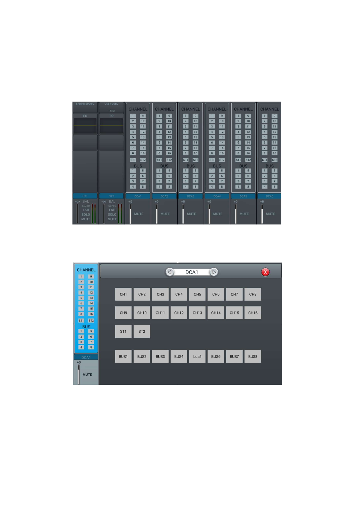
Stereo channel and DCA
13
The ST1 and ST2 input channels are the same as the Mono channel, and also include four
modules: Input Stage, EQ, Bus Send and Output Stage. Click a module to pop up the corresponding
sub page; Click the Close button on the sub page to exit the sub page.
DCA part
On the DCA page there are six groups which can be controlled as needed. By default no group is added, , ,
Double click to enter CHANNEL the DAC option enters the grouping configuration page.
,
Switchable DCA channel
You can freely select the channel to be added
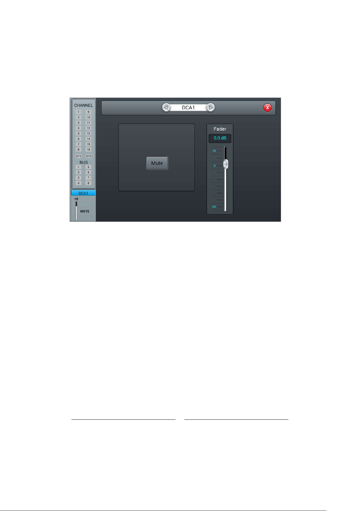
Double click to enter DCA, Fader page
Switchable DCA channel
Can control whether the selected channel is muted
Fader can control the transmission volume of the selected channel
14
15
1
2
3
4
2
3
4
① Input Stage
The module shows the setup of output and effect insert which are assigned from the bus.
② EQ
The module shows the EQ curve of the bus.
③ Input Source
The module shows the channel info sent to the bus
④ Output Stage
The module shows the name of the bus, Pan/BAL value, Solo, Mute, delay setup, fader level and meter
By double pressing the name of the channel can be edited through the soft-keyboard popping up.
Mono Bus Bus 1 ~Bus 4 are Mono busses.
Input Stage Subpage
The page contains Send and Insert. Bus1~Bus4 can send signal to Bus5~Bus8 and L/R master output,
Bus5~Bus8 can only send signal to L/R master output.
OUT3 indicates physical output 3 assigned to the bus, and it shows OUT if there is no bus assigned to the
physical output. Please refer to the page of Patch for operation of assigning busses to physical outputs.

16
2
3
4
5
6
① Switch Channel
Single press the button to switch between previous or next channel on the same layer
② Bus send enable
Single press a bus button, to send channel signal to the bus, press again to disable.
③ PreFader/PostFader toggle selection
The default is PreFader. Single press the button, to toggle PostFader, press again to set it back to default.
④ PAN control
The default is 50|50, the PAN value can be tuned by dragging the slider, or turning the main Encoder on
control panel. Double press the parameter frame to set it back to default.the
⑤ Send level control
Control the level of signal by drag the slider up and down.
⑥ Insert
Press the button of any effect module to insert this module before the EQ on the channel. All effect module
cannot be shared on more than one channel. The busses (Bus1~Bus8, L&R) can be inserted with two effect
modules at the same time, which is sequenced to insert into the bus by the priority of selection. When the
selected module is occupied by other channel or bus, you will see a window popped up and say: he T“
m can be used only once and it is already used by **. Are you sure you want to use the module forcibly
now
odule
“
Yes or No ”

17
2
3
4 5 6 7
EQ Subpage
This Subpage is the same as EQ Subpage of the MIC channel, please refer to MIC channel EQ page.
Output Stage Subpage
The page contains Delay, PAN, Solo, Mute, fader level control and signal level display. (the output of
Bus5~Bus8 and L&R bus is similar with Bus1~Bus4).
① Switch Channel:
Single press the key to switch between previous or next bus channel on the same layer.
② Delay:
Press to enable the delay; the default is disabled. Adjust the delay time by turning the main
the touch screen (fine tuning can be activated by pressing the main Encoder knob). Encoder or on
from 0ms to 200ms, while the default is 0ms.The delay ranges
③ PAN control:
The default is 50|50, the PAN value can be tuned by dragging the slider, or turning the main Encoder
control panel. Double press the parameter frame to set it back to default. on the
④ Solo:
Single press the button to enable monitor, press again to disable it. The default is disabled.
⑤ Mute:
Single press the button to enable mute, press again to disable it. The default is disabled.
⑥ Fader control:
Control the volume of fader level by dragging the slider, or faders on the control panel, the parameter
f real-timely displays the value of fader level. Double press the parameter frame to fast set it back to 0.rame
⑦ Meter level display:
The level meter of channel signal, indicating post-fader signal level of the channel.

18
25
4
7
3
6
Setup page
The page contains Information, Sample Rate, Delay Unit, System, WiFi, Remote, Brightness and
Time & Date.
① Scenes
Shows the name of scenes.
② Information
System Version shows the version of APK, DSP, Fader and other softwares on this console. IP Address
shows the IP address of the console.
③ Sample Rate
The default setting is 48.0 KHz. When single press 44.1 KHz, a window pops up he Sample Rate ofT“
44.1 KHz is only used for Digital Outputs. , then the 44.1 KHz light on, and the 48 KHz light off. The default”
is always 48.0 KHz after rebooting the system
④ Delay Unit
Single press any one among three s t and m buttons, to choose the unit of delay time. The m f“ ”, “ ” “ ”
is m . After rebooting the system, the unit of delay time is always what you set before you had sdefault “ ”
off the console last time.powered
⑤ System
Contains Maintenance and Home Screener two options, please refer to the page of Maintenance
for details.Subpage
⑥ Brightness,
Adjust the brightness of the touch screen.
Six units to indicate the level of brightness, the default is three units. After rebooting the system, the unit
of brightness is always what you set before you had powered off the console last time.
⑦ Crossover setting
Single press SUB8 , the crossover works. At this time, BUS8 works in bass mode, the frequency
adjustment knob can change the crossover frequency. Filter slope is 24dB/oct. The crossover frequency
adjustment range is 40Hz-300Hz. Single press Master L/R button, crossover works. At this time,
L/R works in the full range low cut mode. Master the frequency adjustment knob can change the crossover
Filter slope is Frequency. 24dB/oct. The crossover frequency adjustment range is 40Hz-300Hz. Using
crossovers reasonably can form 2.1 channel reinforcement mode.these two
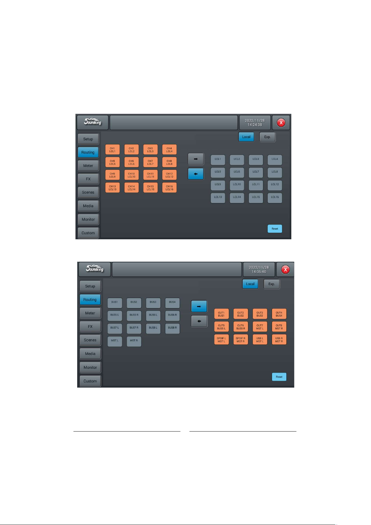
Local input routing, input signals can be allocated to any single or multiple input channels
Local output routing, the output signal can be allocated to any single or multiple output channels
19
Routing Page
Routing page local subpage
Table of contents


