4
OPERATION OF THESE FANS CAN PRODUCE A NEGATIVE
DRAFT IN THEAREA OF THE WATER HEATER PREVENTING
THE PRODUCTS OF COMBUSTION FROM EXHAUSTING
THROUGHTHE CHIMNEY OR VENT PIPE.
Theventing of the waterheater should be inspectedby a qualified
service technician at the time of installation and periodically
thereafter to ensure a down-draft condition does not exist.
DO NOT OBSTRUCT THE FLOW OF COMBUSTION AND
VENTILATING AIR. ADEQUATE AIR FOR COMBUSTION AND
VENTILATIONMUSTBEPROVIDED FORSAFE OPERATION.
EXTENDED NON-USE PERIODS
WARNING
HYDROGENGASCANBEPRODUCEDINAHOTWATERSYSTEM
SERVEDBYTHISHEATERTHAT HAS NOTBEEN USED FORA
LONGPERIODOFTIME(GENERALLYTWO WEEKS OR MORE).
HYDROGEN GAS IS EXTREMELY FLAMMABLE. Toreduce the
risk of injury under these conditions, it is recommended that the
hot water faucet be opened for several minutes at the kitchen
sink before using any electrical appliance connected to the hot
water system. If hydrogen is present, there will probably be an
unusual sound such as air escaping through the pipe as the
water begins to flow. THERE SHOULD BE NO SMOKING OR
OPENFLAMENEARTHE FAUCETATTHETIMEITIS OPEN.
INSULATION BLANKETS
Insulation blankets available to the general public for external
use on gas water heaters are not approved for use on your
State water heater. The purpose of an insulation blanket is to
reduce the standby heat loss encountered with storage tank
water heaters. Your State water heater meets or exceeds
the ASHRAE/IES 90.1-1999 standards with respect to
insulation and standby loss requirement making an insulation
blanket unnecessary.
WARNING
Shouldyouchoosetoapplyan insulation blanket to this heater,
you should follow these instructions. Failure to follow these
instructions can result in fire, asphyxiation, serious personal
injury or death.
•Do not apply insulation to the top of the water heater, as
this will interfere with safe operation of drafthood.
•Do not cover the temperature & pressure relief valve.
•Do not cover the instruction manual. Keep it on the side of
the water heater or nearby for future reference.
•Do obtain new labels from State Water Heaters for
placement on the blanket directly over the existing labels.
HIGH ALTITUDE INSTALLATIONS
WARNING
INSTALLATIONS ABOVE 2000 FEET (610 METERS) REQUIRE
REPLACEMENTOF THE BURNER ORIFICE IN ACCORDANCE
WITH SECTION 8.1.2 OF THE NATIONAL FUEL GAS CODE
(ANSIZ223.1).FAILURETOREPLACETHEORIFICEWILLRESULT
INIMPROPERANDINEFFICIENTOPERATIONOFTHEAPPLIANCE
RESULTING IN THE PRODUCTION OF INCREASED LEVELS OF
CARBONMONOXIDEGASINEXCESSOFSAFELIMITSWHICH
COULDRESULTINSERIOUSPERSONALINJURYORDEATH.
You should contact your gas supplier for any specific changes
which may be required in your area.
As elevation above sea level is increased, there is less oxygen
per cubic foot of air. Therefore, the heater input rate should be
reduced at high altitudes for satisfactory operation with the
reduced oxygen supply. Failure to make this reduction would
result in an overfiring of the heater causing sooting, poor
combustion and/or unsatisfactory heater performance.
REQUIREMENTS
Ratings specified by manufacturers for most appliances apply
for elevations up to 2000 feet. For elevations above 2000 feet,
ratings must be reduced at the rate of 4% for each 1000 feet
above sea level. For example, if a heater is rated at
120,000 Btuh at sea level, to rate the heater at 4000 feet, you
subtract4 (once for each thousand feet) x.04(4% input reduction)
x120,000 Btuh(original rating) fromthe original rating. Therefore,
tocalculatethe inputrating at4,000 feet:4 x.04x 120,000=19,200
Btuh, 120,000 - 19,200 = 100,800 Btuh. At 6000 feet the correct
input rating should be 91,200 Btuh.
The input reduction is primarily achieved by reducing the size of
the main burner orifices. To do this, the main burner orifices
require replacement with orifices sized for the particular
installation elevation. Correct orifice sizing and parts may be
obtained from State Water Heaters. When ordering, be sure to
state the model number and the altitude of the location where
the water heater is being installed.
Upon completion of derating of the heater, adjustment to the gas
pressure regulator may be required. See CHECKING THE
INPUT section in this manual for inlet and manifold pressure
requirements.
Also due to the input rating reduction required at high altitudes,
the output rating of the appliance is also reduced and should be
compensated for in the sizing of the equipment for application.
FEATURES
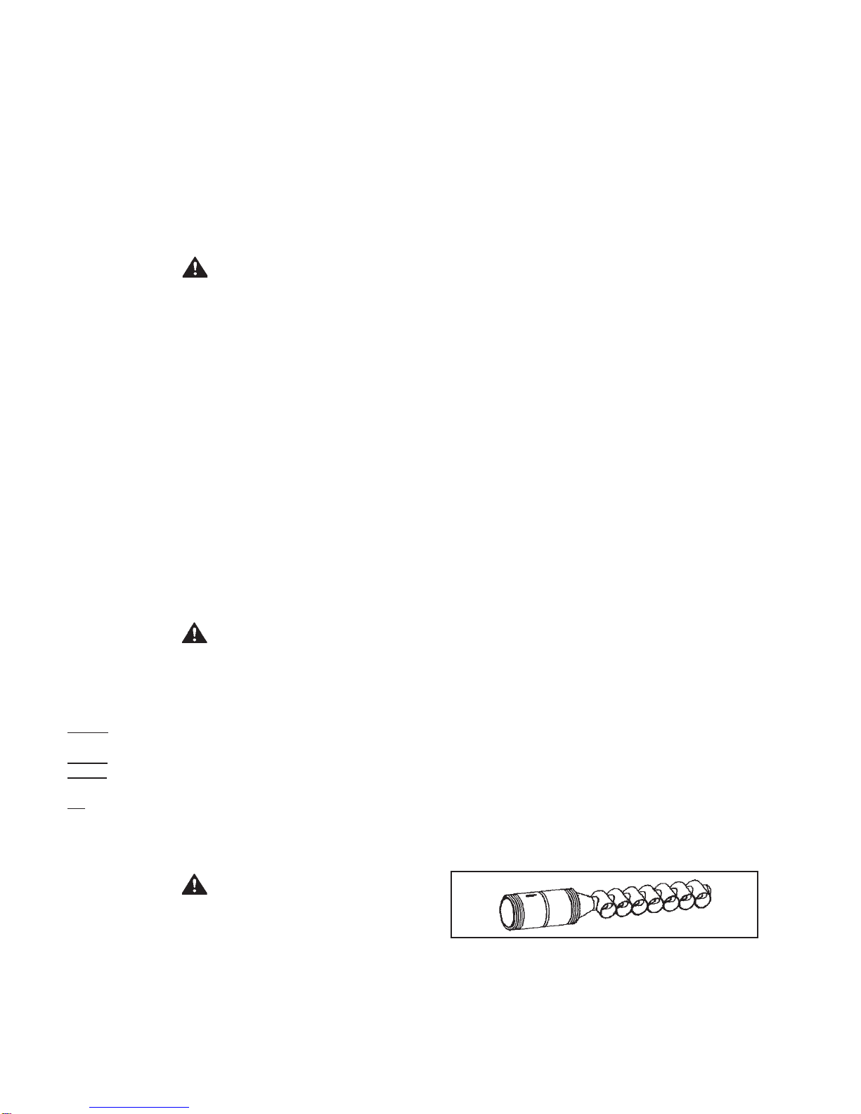
SELF-CLEANING HYDRO-CANNON
These units include a self-cleaning hydro-cannon installed in
the front water inlet. See figure 2. The hydro-cannon must be
oriented correctly for proper function. There is a marked range
on the pipe nipple portion of the hydro-cannon, that must be
aligned with the top of the inlet spud. A label above the jacket
hole has an arrow that will point to the marked portion of the
pipe nipple if the orientation is correct. If the arrow does not
point within the marked range on the pipe nipple, adjust the pipe
nipple to correct. Apipe union is supplied with the hydro-cannon
to reduce the probability of misaligning the hydro-cannon
accidentally while tightening the connection to the inlet water
supply line. Improper orientation of the hydro-canon can cause
poor performance of the heater and can significantly reduce
outlet water temperatures during heavy draws.
NOTE: The inlet may have 1, 2 or 7 cross- tubes.
FIGURE2
HIGH LIMIT SWITCH
The digital thermostat (Figure 3) contains the high limit (energy
cutoff) sensor. The high limit switch interrupts main burner gas
flow should the water temperature reach 203°F (195°C).


 Operation and maintenance instructions")