A-TS TECHNOLOGY DT100-2S0004G User manual

A-TS 1
https://a-ts.cn/en/
DT100 Series Inverter/VFD/AC
Drive User Manual
A-TS TECHNOLOGY
CORPORATION LIMITED
A-TS 2
https://a-ts.cn/en/
DECLARATION
Without written permission, reprint or copy is strictly forbidden.
A-TS Technology Corporation Limited
All rights reserved
Version
Product
Realse Date
Note
V-18-02
DT100
27.11.2018
N/A

A-TS 3
https://a-ts.cn/en/
Contents
DECLARATION.....................................................................................................2
1. Foreword..........................................................................................................6
2. Inspection ........................................................................................................7
3. Safety Precautions..........................................................................................8
3.1 Safety definition ............................................................................................8
3.2 Safety items ...................................................................................................8
3.3 Precautions..................................................................................................12
4. Specifications and Optional Parts ...............................................................16
4.1Specifications...............................................................................................16
4.2 Products Series Introduction .....................................................................17
4.2.1 DT100 Models....................................................................................17
4.2.2 Ordering information of DT100 series ................................................18
4.2.3 Demision............................................................................................19
4.2.4 LED Keypad Display Unit Size...........................................................19
4.2.5 Optional Parts ....................................................................................20
5. Installation and Wiring..................................................................................21
5.1 Installation ...................................................................................................21
5.2 Wiring...........................................................................................................22
5.2.1 Overview............................................................................................22
5.2.2 Power Terminals.................................................................................23
5.2.3 Control Circuit Wiring.........................................................................23
6. Operation Procedures...................................................................................30
6.1 Operation Guide ..........................................................................................30
LED Keypad................................................................................................30
6.1.1 Keypad Function Explanation ............................................................30
6.1.2 Indicator Description ..........................................................................31
6.1.3 Parameter Setting Method .................................................................32
6.1.4 Motor parameters self learning...........................................................32
6.1.5 Password setting................................................................................33
7. Parameters.....................................................................................................34

A-TS 4
https://a-ts.cn/en/
7.1 Basic Parameters ( P0 ) .............................................................................34
7.2 Motor Parameter ( P1 ) ..............................................................................37
7.3 Start/Brake Parameter ( P2 ) .....................................................................39
7.4 Flux vector control parameters ( P3 ) ......................................................41
7.5 Current vector control parameter ( P4 ) ...................................................44
7.6 Multi-function terminal ( P5 ) ....................................................................44
7.7 Output terminal control parameters ( P6 ) ...............................................51
7.8 Closed-loop PID control ( P7 ) ..................................................................56
7.9 MS parameters ( P8 ) .................................................................................59
7.10 Enhanced function ( P9 ) .........................................................................59
7.11 Display Control Parameters ( PA ) ..........................................................63
7.12 Communication ( PB ) .............................................................................64
7.13 Professional parameters ( PC ) ..............................................................66
7.14 PLC parameters ( PD ) .............................................................................66
7.15 Constant-pressure water supply ( PE ) ...............................................69
7.16 Protection ( PL ) .......................................................................................69
7.17 Operation Time and Temperature of Cooling Fan ( PN ) ....................72
7.18 Protection of Parameters ( PP ) ..............................................................72
7.19 Factory Default ( PU ) ..............................................................................73
8. Trouble shooting...........................................................................................74
9. Maintenance...................................................................................................83
9.1 Routine Maintenance ..................................................................................83
9.2 Periodic Maintenance..................................................................................84
9.2.1 General Inspection:............................................................................84
9.2.2 Replacing Easily-worn Parts ..............................................................85

A-TS 5
https://a-ts.cn/en/
9.2.3 Storing Inverters.................................................................................86
9.2.4 Warranty.............................................................................................86
10. Parameter profiles.......................................................................................87
11. Communication Protocal..........................................................................121
11.1 Communication Mode.............................................................................121
11.2 Protocol Format.......................................................................................121
11.3 Protocol Function....................................................................................122
11.4 Instruction................................................................................................128
11.5 The scaling rule of Inverter.....................................................................129

A-TS 6
https://a-ts.cn/en/
1. Foreword
The DT100 series inverter is provided by A-TS Technology Co., Ltd.
in China.
With the unique control method, high torque, high accuracy and wide
speed-adjusting range, DT100 series satisfies high performance
requirements. It has anti-tripping function and capabilities of adapting
severe power network, temperature, humidity, and dusty environment,
which improves the products reliability markedly.
This manual provides guidance on installation, wiring, parameters
setting, trouble-shooting, and routine maintenance, etc.. In order to
ensure the correct installation and operation of the inverter, please read
this manual carefully before use and keep it safely.
Thank you for choosing A-TS.
A-TS, advanced technologies, advanced things.

A-TS 7
https://a-ts.cn/en/
2. Inspection
Product Overall Checking
Don’t install or use any inverter that is damaged or have defective parts,
otherwise it may cause injury !
Check the following items when unpacking.
1. Check the nameplate, make sure inverter model matches your order.
The box contains the inverter and user manual.
2. Inspect the whole exterior of inverter to ensure there are no scratches
or other damage caused by transportation. If the inverter is damaged
during transportation, or you find any missing or damage, please contact
A-TS or your local supplier immediately.
3. If you have ordered optional parts, ensure the optional parts match
your order.
If there is any damage in the inverter or other parts, please contact the
local supplier or A-TS as early as possible.
A-TS 8
https://a-ts.cn/en/
3. Safety Precautions
To have a thorough understanding, please read this manual carefully
and follow all safety precautions before moving, installing, operating and
servicing the inverter. If it’s ignored, physical injury or even death may
occur, and damage may occur to the devices.
For any injury or loss caused by improper operation, A-TS will not
take the responsibility.
3.1 Safety definition
In this manual, the safety precautions are sorted to “Danger” or
“Caution”
DANGER
Operations without following instructions may cause fire, severe
injury, or even death.
Operation without following instructions may cause medium or
minor injury or property damage.
3.2 Safety items
Before installation:
DANGER
Please do not install the equipment if you find water seepage,
component missing or damage upon unpacking.
Do not install the equipment if the packing list is not conform to the
product you received.
Please use the insulating motor above B class; otherwise it may
result in serious injury or even death due to electric shock !
Please do handle the equipment carefully during transportation to
prevent damage to the equipment.
Do not touch the components with your hands directly. Improper
operation will result in static electricity damage.
!
CAUTION
!
CAUTION

A-TS 9
https://a-ts.cn/en/
During installation:
DANGER
Please install the inverter on the fireproofing material ( such as
metal ) to prevent fire, and keep it away from combustible materials !
Do not loosen the fixed screws of the components.
When you need to install two or more inverters in one cabinet,
cooling fans should be provided,and the installation positions should be
arranged properly to make sure that the ambient temperature is below
45℃. Otherwise it could cause fire or damage to the devices.
Install the inverter in places without vibration or direct sunlight.
Do not drop any wire end or screw into the inverter. Failure to
comply will result in damage to the inverter.
At wiring:
DANGER
Wiring must be performed only by qualified personnel under
instructions in this manual. Improper operation may cause unexpected
accidents.
A circuit breaker must be used between the power supply and
inverter to isolate. Otherwise the fire may be caused !
Never wire the inverter unless the power supply is totally cut off !
The ground terminal must be grounded properly by standard to
avoid electrical accident !
Pay attention to the marks of the wiring terminals and ensure
correct wiring. Never connect the power cables to the output terminals
( U,V, W ) of the inverter.Otherwise it will cause damage to the inverter !
The wring must comply with the EMC requirements and safety
standards in the region. Use wire diameter sizes recommended in the
manual, otherwise it may cause an accident !
Use the shielded cable for the encoder, and ensure that the
!
CAUTION
!
CAUTION
A-TS 10
https://a-ts.cn/en/
shielding layer is reliably grounded.
Never connect the braking resistor between the DC bus terminals
( + ) and ( - ) , or it may cause a fire !
Before power-on:
DANGER
Make sure the following requirements, failure to comply will cause
damage to the inverter.
–The power and voltage level of the power supply is consistent with
the rated voltage of the inverter.
–The input terminals ( R, S, T ) and output terminals ( U, V, W )
are properly connected.
–No short-circuit exists in the peripheral circuit.
–The wiring is secured.
Do install the cover properly before power-on, to prevent the
danger of electric shock !
Do not perform the voltage resistance pressure test on any part of
the inverter, because such test has been done in the factory. Otherwise, it
will cause accidents.
All the peripheral devices must be connected properly under the
instructions in this manual. If not, it may cause an accident !
After power-on:
DANGER
Do not open the cover after power-on, otherwise it may cause
electric shock and damage !
Do not wire or operate the inverter with wet hands, otherwise it
may cause electric shock !
Do not touch any inverter terminals ( including the control
terminals ) , otherwise it may cause electric shock !
At the beginning of power-on, the inverter will carry out safety
testing for external electric circuit automatically. Do not change the
!
CAUTION

A-TS 11
https://a-ts.cn/en/
default settings of the inverter. Otherwise it will cause damage to the
devices.
If you need parameter identification, please notice the risk of
injuries in motor rotation. Do not touch the rotating part of the motor
during the motor auto-tuning or running. Or, it may cause an accident !
Please do not arbitrarily change the default parameters of inverter;
otherwise it may result in equipment damage !
During operating:
DANGER
When the user selects the function re-starting, please do not stay
close to the mechanical equipment, otherwise it may cause personal
injury !
Do not touch the radiator, fan or the discharging resistor to check
the temperature, otherwise it may get burned !
Only qualified personnel shall detect the signal, otherwise it may
cause personal injury or equipment damage !
When the inverter is running, please don’t let any sundries fall into
the device, or it may cause equipment damage !
Please do not start/stop the AC drive by turning the contactor
ON/OFF, otherwise it would cause device damage !
During maintenance:
DANGER
Ensure the inverter is disconnected from all power supplies before
starting repair or maintenance. Never repair or maintain the inverter with
electrification, otherwise it may cause injury or electric shock !
Do not repair or maintain the inverter when power-on. Before the
maintenance or repair, wait at least ten minutes after power off and ensue
the inverter “CHARGE” light off, otherwise the residual charge on the
capacitor may cause personal injury !
!
CAUTION
!
CAUTION

A-TS 12
https://a-ts.cn/en/
Only qualified personnel can repair and maintain the inverter,
otherwise it will cause personal injury or device damage!!
Set and check the parameters again after the inverter is replaced.
Only after power-off, the pluggable components can be plugged or
removed.
Generally, the rotating motor feeds back power to the inverter.
Ensure the inverter is disconnected from the motor before starting repair
or maintenance.
3.3 Precautions
Insulation of the motor
Before using the inverter, the insulation of motor must be checked,
especially, when it is used for the first time or it has been stored for a long
time. The poor insulation of the motor winding may cause damage to the
inverter. The motor must be disconnected from the inverter during the
insulation test. Please use 500V insulation tester to measure the
insulation resistance. It should not be less than 5MΩ.
Thermal protection of the motor
In model selection, if the rated capacity of motor and inverter does not
match, especially when the rated power of inverter is greater than the
motor, make sure to adjust the motor protection-related parameters in the
inverter or the pre-installed thermal relay in the motor for motor thermal
protection.
Working above power frequency
The inverter can provide 0Hz-60Hz output frequency, if the customer
needs to run at 50Hz or above, please consider the affordability of
mechanical devices.
Vibration of mechanical devices
When the inverter output frequency reaches a certain value, you may
encounter a mechanical resonance point of the load devices. It can be
avoided by setting parameters about the hopping frequency in the
inverter.
Regarding motor heat and noise

A-TS 13
https://a-ts.cn/en/
Because the output voltage of the inverter is the PWM wave,it
contains some harmonics wave, Therefore, there will be some increase in
temperature、noise、libration in motor and work-frequency.
Varistors for surge protection and capacitors used to improve the
Power Factor
Don’t connect any varistor or capacitor to the output terminals of the
inverter, as the inverter output voltage waveform is pulse wave.
Otherwise, it may cause tripping or damage to devices.
If the circuit breaker or contactor needs to be connected between
the inverter and the motor, please only operate them when the inverter
has no output. Do not turn off the contactor when the inverter is active. It
is to avoid damage to the inverter. Otherwise it may cause damage to the
devices.
Using outside rated voltage
The inverter could not be used at an operating voltage out of the
specified range. If needed, please use suitable voltage regulation device.
Try to change the three-phase input into two-phase input
It’s not permitted. Don’t use the three-phase inverter as a two-phase
one, or it will result in failure or damage.
Protection against lightning stroke
There are transient surge suppressors inside the inverter. They can
protect it against lightning stroke. If it is in frequent lightning stroke area,
more protection device should be added in the leading end.
Derating due to altitude
Derating must be considered when the inverter is installed at a
high altitude, above 1000m. The cooling effect of the inverter is less
effective in the thin air. For more details, please contact your local
supplier or A-TS.
For some special usages
If the customer needs to use the wiring diagram that the manual
did not mentioned, such as the common DC bus, please contact local
supplier or A-TS.

A-TS 14
https://a-ts.cn/en/
Disposing unwanted inverters
1 ) The capacitors and PCB may explode when they are burnt.
2 ) Poisonous gas may be generated when the plastic parts like front
covers are burnt.
3 ) Please dispose the inverter as industrial refuse.
Requirement on residual current device ( RCD )
The inverter generates high leakage current during running, which
flows through the protective earthing ( PE ) conductor. Thus it is
necessary to install a type-B RCD at primary side of the power supply.
When selecting the RCD, you should consider the transient and
steadystate leakage current to the ground that may be generated at the
inverter startup and running. You can select a specialized RCD with the
function of suppressing high harmonics or a general-purpose RCD with
relatively large residual current.
High leakage current warning
The inverter generates high leakage current during running, which
flows through the PE conductor. Earth connection must be done before
connection of power supply. Earthing shall comply with local regulations
and related IEC standards.
Surge suppressor
The inverter has a built-in voltage dependent resistor ( VDR ) for
suppressing the surge voltage generated when the inductive loads
( electromagnetic contactor, electromagnetic relay, solenoid valve,
electromagnetic coil and electromagnetic brake ) around the inverter
are switched on or off. If the inductive loads generate a very high surge
voltage, use a surge suppressor for the inductive load or also use a
diode.
Do not connect the surge suppressor on the output side of the
inverter.
Adaptive motor
1 ) The standard adaptive motor is four-pole squirrel-cage
asynchronous induction motor. If it is not the motor mentioned above,

A-TS 15
https://a-ts.cn/en/
customer could select the inverter according to rated current of the motor.
If you need the inverter matches permanent magnet synchronous motor,
please ask local supplier or A-TS for support.
2 ) The cooling fan of non-variable frequency motor and the rotor
shaft is connected by coaxial connection device. The fan cooling effect
decreases along with the rotational speed. Therefore, when it’s
overheated, more fan should be installed or change to use the variable
frequency motor.
3 ) There are built-in standard adaptive parameters for motors in the
inverter. According to the actual situation or requirements, motor
parameter recognition ( auto-tuning ) needs to be performed or
unique default value should be set, in order to match with the actual
conditions as far as possible. Otherwise it will affect the running
performance and protection capability.
4 ) If the short circuit occurs in the cable or motor, it will cause alarm in
the inverter, or even explosion. Therefore, firstly please do perform the
insulation and short circuit tests, when the motor and cable are initially
installed. The same tests should also be carried out in the routine
maintenance regularly. Please kindly note that the inverter should be
separated totally, when doing such tests.
A-TS 16
https://a-ts.cn/en/
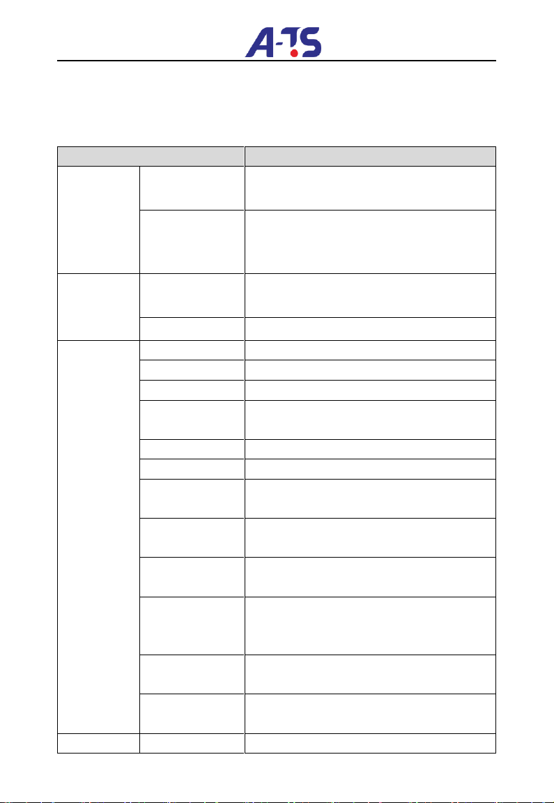
4. Specifications and Optional Parts
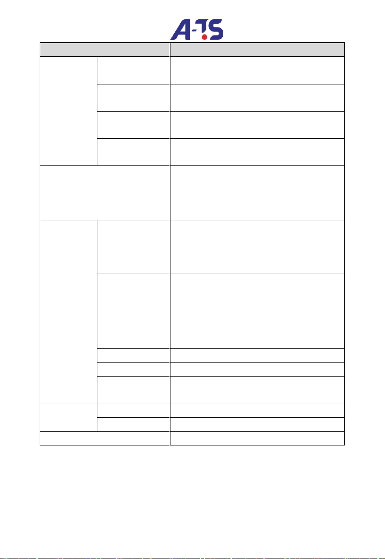
4.1 Specifications
Table 4-1 DT100 Specifications
Item
Description
Input
Rated voltage;
Frequency
DT100-4Txxxxx: 380V~440V; 50Hz/60Hz
DT100-2Sxxxxx: 200V~240V; 50Hz/60Hz
Permissible
fluctuation range
Voltage contant fluctuate ≤±10%, Transient
fluctuate: -15%~+10%, out of balance voltage
rate: ≤3%, frequency fluctuation:≤5%
Output
Rated voltage
DT100-4Txxxxx: 0~380V/440V
DT100-2Sxxxxx: 0~200V/240V
Frequency
0Hz~650Hz
Control
functions
Modulation mode
Flux vector PWM modulation
Speed range
1: 100
Starting torque
180% rated torque at 0.5Hz
Accuracy of speed
at steady state
≤±0.5%rated synchronous speed
Torque boost
Auto torque boost, Manual torque boost
Acc/Dec curve
Linear
Jog
Jog frequency, Acc/Dec time,
Jog interval are adjustable
Multi-speed
operation
15 sections of frequency. By the built-in PLC or
terminals.
Closed-loop
control
Analog closed-loop
Auto voltage
regulation
( AVR )
Steady output voltage,
when power network voltage fluctuates.
Auto current
regulation
Current amplitude is regulated
to avoid overcurrent automatically
Auto carrier
regulation
Adjust the carrier frequency automatically,
according to the load characteristics
Special
Internal counter
External pulse signal is counted by X terminal
A-TS 17
https://a-ts.cn/en/
Item
Description
function
Command
channel
Via operation panel, terminals and serial port
Frequency setting
channel
Digital setting, AIand communication
Auxiliary
frequency setting
Flexible auxiliary frequency selectable
Analog output
terminals
0/4~20mA and 0/2~10V ( selectable )
Protection function
Phase loss failure protection, Over/Under
current protection,
Over/Under voltage protection,
Overheat and overload protection.
Environment
Operating
environment
In-door, no direct sunlight, no dust, no corrosive
gas or
combustible gas,no oil mist, vapor, drip, or
salinity.
Altitude
Less than 1000m ( Above 1000m derating )
Ambient
temperature
-10℃~+40℃, derating is required from 40~
50℃;
Above 40℃, each degree rised, derating 2%;
Highest temperature: 50℃.
Humidity
Less than 95% RH, no condensing
Vibration
Less than5.9m/s2( 0.6g )
Storage
temperature
-40℃~+70℃
Enclosure
Protection level
IP20
Cooling
Fan cooling, natural cooling
Mounting mode
Mounted in the cabinet
4.2 Products Series Introduction
4.2.1 DT100 Models
A-TS 18
https://a-ts.cn/en/
Table 4-2 DT100 general purpose series
Model
Rated
capacity
( KVA )
Rated output
current ( A )
Applicable motor
power ( KW )
DT100-2S0004G
1.0
2.5
0.4
DT100-2S0007G
1.5
4.0
0.75
DT100-2S0015G
3.0
7.5
1.5
DT100-2S0022G
4.0
10.0
2.2
DT100-4T0007G
1.5
2.3
0.75
DT100-4T0015G
3.0
3.7
1.5
DT100-4T0022G
4.0
5.0
2.2
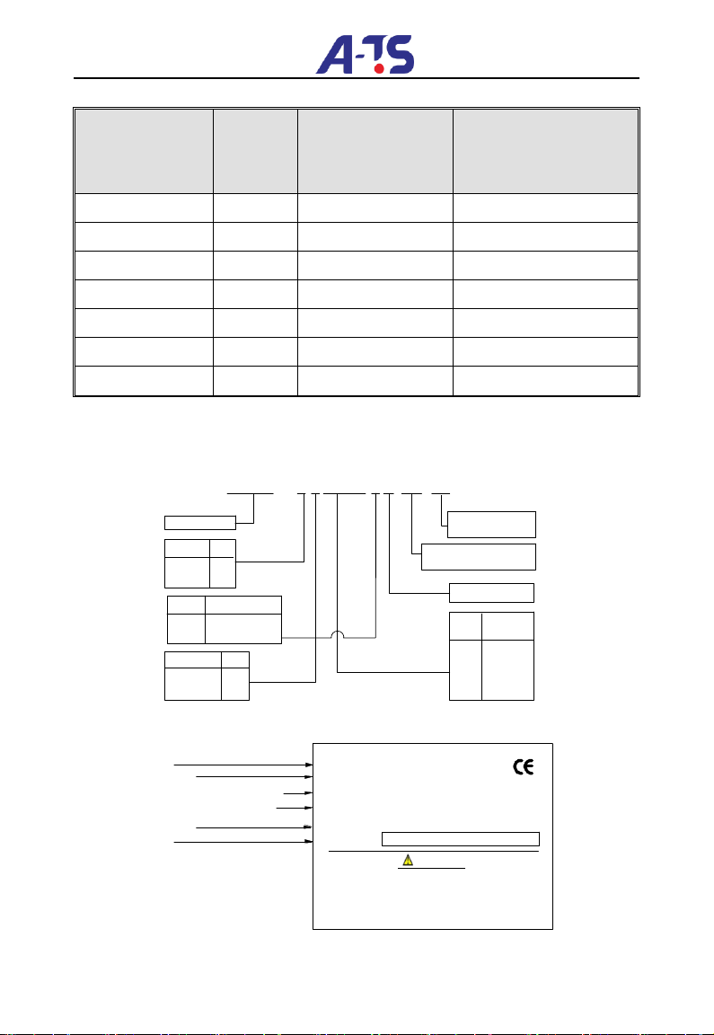
4.2.2 Ordering information of DT100 series
Please refer to Figure 4-1a and Figure 4-1b.
Series
Power
(KW)
Code
0004
0015
0022
0.4
1.5
2.2
-4 T 0 0 2 2 G B
DT100
Input Code
Three Phase T
Single Phase
Voltage Code
220V 2
380V 4
Code Type
Constant
torque
G
-XX-XX
Special machine code:
GM Series changed to default
Design version:0~99
0007 0.75
S
Built - in brake unit
Figure 4-1a DT100 Model Designation
DT100-4T0022G
2.2KW
3PH AC 380-440V 5.8A 50/60HZ
3PH AC 0-440V 5.0A 0~650HZ
MODEL :
POWER :
INPUT
:
OUTPUT:
S/N:
Model
Motor power
Rated input voltage, current and frequency
、
、
Design version
WARNING
* Risk of electric shock
*
*
VS 0000 0219 0000 0000
Barcode
:
Output voltage range rated current and
frequency range
Wait 10mins after power down before removing
the cover
Follow all the instructions in the manual before use
Figure 4-1b DT100 series nameplate

A-TS 19
https://a-ts.cn/en/
4.2.3 Demision
Please refer to Figure 4-2
Figure 4-2 DT100 series inverter size
Note: Net weight, 1.04KG
Gross weight ( including user manual after package ) , 1.22KG.
4.2.4 LED Keypad Display Unit Size
Through it, operation and configuration of the inverter can be done.
Please refer to its size and configuration in Figure 4-3.
Figure 4-3 Keypad display unit
Model No.
L
( mm )
W ( mm )
H
( mm )
Weight
( Kg )
DT100-2S0004G
146
92
123.52
1.22
DT100-2S0007G
DT100-2S0015G
DT100-2S0022G
A-TS 20
https://a-ts.cn/en/
DT100-4T0007G
DT100-4T0015G
DT100-4T0022G
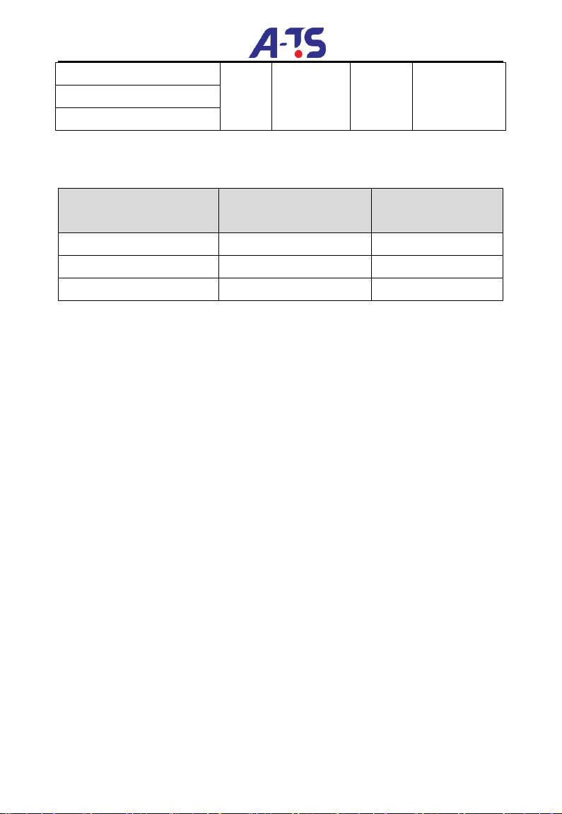
4.2.5 Optional Parts
Table 4-3 Braking resistor suggested
Model
Suggested value of
resistance
Suggested power
DT100-4T0007G
250-350Ω
100W
DT100-4T0015G
200-300Ω
200W
DT100-4T0022G
100-250Ω
250W
DT100 series inverter ( 3phase product ) is equipped with braking unit.
If there is a need for energy-consuming braking, please select a braking
resistor in Table 4-3.
The Table 4-3 above is a guide reference only. Users can choose
different braking resistance and power according to each application.
However, please remember that the braking resistance shouldn’t be
lower than the above suggested value, but the power is allowed to be
higher than the recommend numbers. Users need to select the right
braking resistors according to each application case,there are quite a few
aspects which will determine your choice of the resistors, such as the
power of the motor, system inertia,deceleration time, the energy of the
load etc. The greater the system inertia is, the shorter the required
deceleration time is required,then the braking frequency will be increased,
which means you need to choose a bigger power braking resistor with a
lower braking resistance.
Note: the 220V single phase inverter is not with buit-in brake unit.
This manual suits for next models
7
Table of contents


