Solatube Energy Care Optima 160 DS User manual
Brighten Up®Series installation guide
Solatube 160DS (250mm ø) and Solatube 290DS (350mm ø)
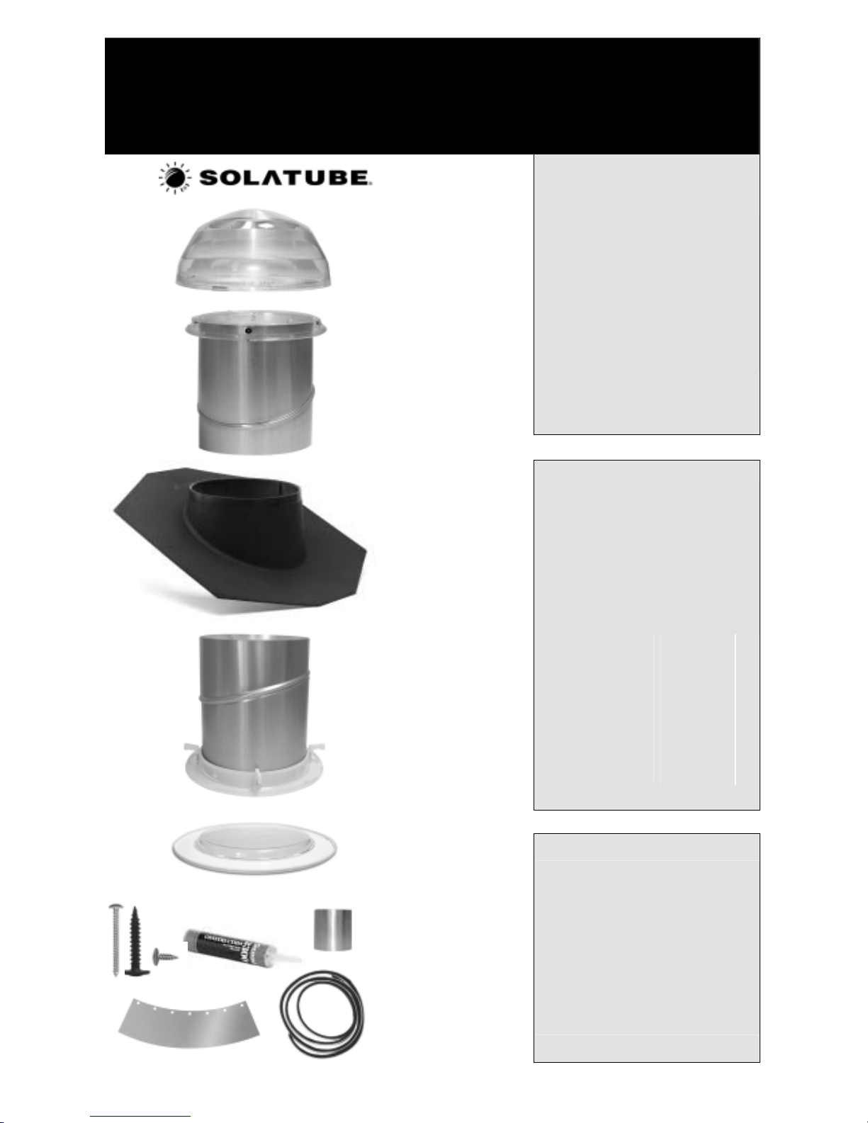
Parts List
Roof dome with patented
Raybender®3000
technology Please read
these
instructions fully
before beginning
installation
Top tube assembly
(305mm long) incorporating
0-30º adjustable angle and
dome ring
Roof flashing to suit
specified roof type
(Solatube 160DS
slate/plain tile roof flashing
shown)
Bottom tube assembly
(305mm long) incorporating
0-30º adjustable angle and
ceiling ring with integrated
twist lock mechanism– see
note right re additional
extension tubes
Additional extension tubes?
You will receive a top tube and bottom
tube assembly in your Solatube kit.
Together these assemblies give an install
distance (roof to ceiling) of up to 400mm
(16"). This is generally sufficient for flat
roofs, vaulted ceilings, or very shallow
pitch roofs. For greater install distances
please check you have purchased
sufficient extension tubes to meet your
required install distance:
Up to:
400mm (16”)
960mm (38”)
1520mm (60”)
2080mm (82”)
2640mm (104”)
3200mm (126”)
3760mm (148”)
4320mm (170”)
Ext Tubes:
0
1
2
3
4
5
6
7
Double glazed diffuser
Seal & fastener kit
LightTracker™dome reflector
Flashing sealant - if required
Aluminium tape roll
Flashing screws (50mm)
Dome ring screws (25mm)
Tube screws (10mm)
Expansion joint seal
Important notice
Please ensure that all components have
arrived in perfect condition before starting
the installation.
If any components are damaged in
transit, the complete, unused system
should be returned for replacement.
We do not accept return of individual
system components.
Please note that top & bottom tube
assemblies are delivered one inside the
other.
©SolaLighting Limited 2007

Warning
Do not proceed with the installation until you have read and understood the entire installation guidelines, including the points below.
If you have any questions or require clarification of any installation procedures, please contact your Solatube®supplier.
Solatube (or seller) assumes no responsibility or obligation whatsoever for the failure of an architect, contractor, installer or building
owner to comply with all applicable laws, ordinances, building codes, energy codes, fire and safety codes and requirements, and
adequate safety precautions. Installation of this product should be attempted only by individuals skilled in the use of the tools and
equipment necessary for installation. The supplier accepts no responsibility for incorrectly installed or non-appropriate applications.
Protect yourself and all persons and property during installation. If you have any doubt concerning your competence or expertise,
consult a qualified expert before proceeding. In addition, please check the Health & Safety Executive website for advice on safe working
at height http://www.hse.gov.uk. Installation is at your own risk.
Solatube product installations may be dangerous owing to the locations of the work to be undertaken. The hazardous conditions include,
but are not limited to, the following:
• During installation, the Solatube reflective tubes may focus sunlight potentially causing concentrated light
and heat. Keep the protective film on the reflective tubing prior to installation and the tubing away from
potentially flammable material.
• Sheet metal edges may be sharp. Use protective gloves to avoid lacerations.
• Installation requires climbing and working at dangerous heights, including on ladders, scaffolding, roofs and
in attic spaces. Use extreme caution to minimize risk of accidental injury and property damage including, but
not limited to, the points below:
o Clear the area below your workspace of all people, animals and other items.
o Avoid working on surfaces that are slippery or wet and use footwear with excellent traction.
o Use only strong, well-supported and appropriate ladders.
o Work only in calm, dry weather.
o When in the attic, ensure that your weight is supported at all times with structurally sound framing;
dry wall material is not designed to carry a person’s weight.
o Reduce the risk of fire, electric shock, and personal injury by following basic safety precautions
when using electric tools; always wear safety goggles or other suitable eye protection and ensure
work area is clear of all electrical wires, gas pipes, water pipes and other obstacles.
o When working in the attic or other dusty areas, use of a mask or respirator is recommended to
avoid lung irritation. Attic spaces may be dark, confined, and subject to extreme temperatures.
Beware of sharp protruding objects. Do not attempt installation without having someone within
range of your voice or close enough to come to your aid if necessary.
o Only suitably qualified persons should undertake any electrical wiring.
Installation tips & safety advice
These instructions are a step-by-step guide for the installation of a Solatube 160DS and 290DS.
In general, a Solatube 160DS can provide enough daylight to illuminate a dark area of up to 13 sq m (150 sq ft). A Solatube 290DS can
provide enough daylight to illuminate a dark area of up to 22 sq m (250 sq ft). Both examples are based on a 2.44 m (8ft) ceiling height
with a 1.83 m (6 ft) tube length. For larger areas, you may need to install more than one Solatube. This information is for guidance
purposes only.
Allow at least 4 hours for the installation, particularly if this is your first installation.
During the day, turn off all the lights in the room to see how much natural light comes in through the windows (if any). You should then
be able to determine the best position for the Solatube diffuser.
Avoid roof dome locations shaded by trees, ridges and chimneys, or near water channels or valleys.
Avoid attic areas with obstructions such as gas, water or drain pipes, air ducts, flues or furnaces, fixed storage tanks.
Measure the distance between the roof and the ceiling to ensure you have ordered sufficient reflective tubing to cover the distance.
All reflective extension tube joints should overlap a minimum of 50mm and be fixed together using the self-tapping screws and
aluminium tape provided.
All adhesives, seals and tapes should be applied to a dry surface. The ideal working temperature is approximately 22°C.
Ensure your roof is in an appropriate condition to support the work necessary for a Solatube installation without damaging its
waterproofing properties.
Solatube will generally perform best if the roof dome is located on the south, east or west elevation. If the roof dome is to be positioned
on a north facing elevation, positioning the roof dome as high as possible on the roof will enhance performance.
You may choose to support any extension tubes with a wire or similar retainer fixed to the rafters if the extension tubes are at an angle
away from the vertical.
In particularly cold climates, it is advisable to tape a jacket of insulating material (not provided) around the outside of the extension tubes
and up into the void between the top tube assembly and roof flashing to prevent the possibility of condensation build-up on the exterior
of the components within the roof void. Contact your Solatube supplier if you have any questions. When the Solatube is installed, it is
common for it to condensate lightly on the inside of the dome for the first few weeks until humid air inside the tube dissipates. The dome
is designed to collect internal moisture and direct it to the outside of the flashing. The Solatube is completely sealed at the ceiling level
to prevent warm moist air from inside the house migrating up the tube.
2
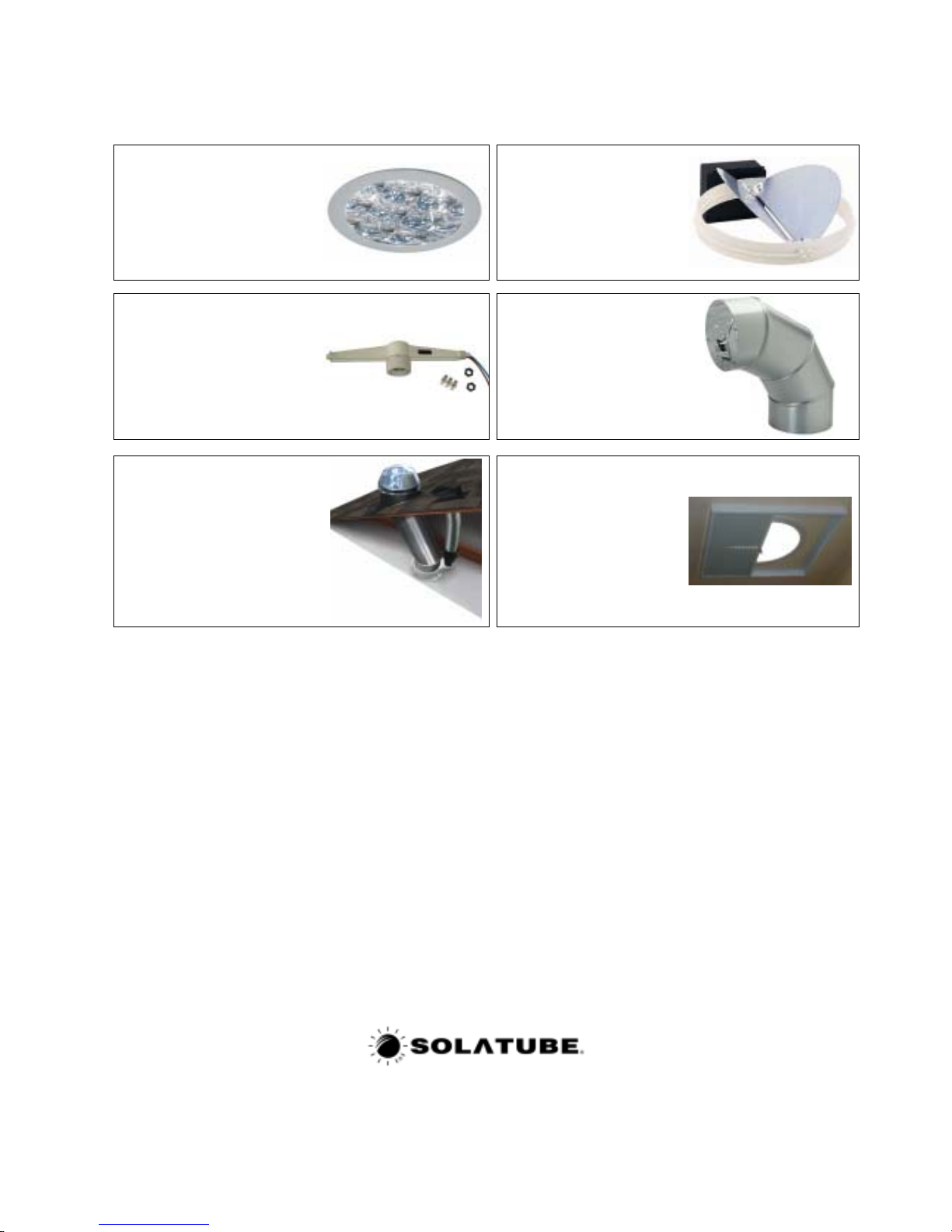
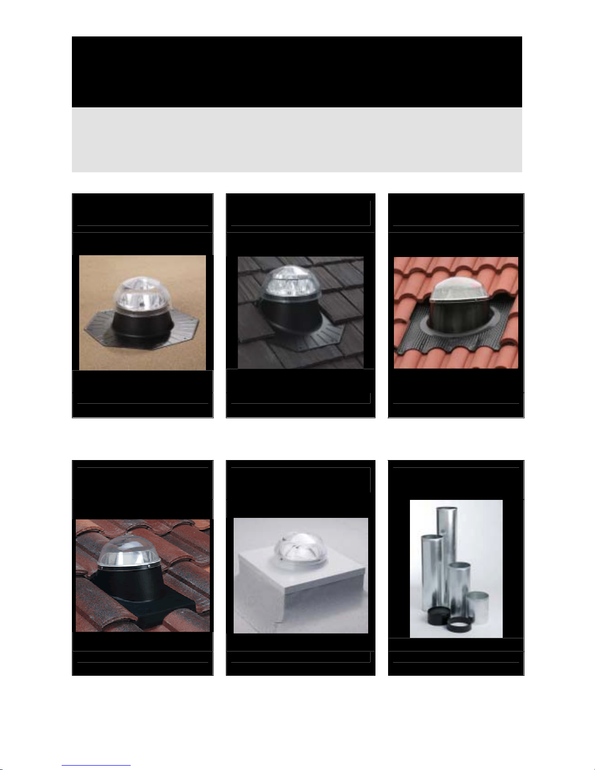
Solatube optional accessories
If you have purchased any of the following optional Solatube accessories, please read the instructions
supplied with the accessory before proceeding with the Solatube installation as some accessories cannot be
installed as a retrofit.
Optiview®diffuser
Available for both Solatube sizes, the
technologically advanced OptiView®
diffuser uses a multiple Fresnel lens
system with a stunning architectural
look to deliver crystal clear daylight.
To fit this accessory, follow the
installation instructions in this guide.
Electric daylight dimmer
kit*
Available for all Solatube sizes,
controls the amount of daylight
required from the convenience
of a low voltage switch.
Integral electric light kit*
Available for both Solatube sizes,
provides the convenience of a
switched light for night time use.
Additional 0-90° angle
Available for both Solatube
sizes, allows easy installation
around obstructions or corners.
Bathroom ventilation kit*
Available for the Solatube 160DS
only, offers discreet style and high
performance, ideal for bathrooms
and shower rooms.
Manual daylight dimmer
Available for both Solatube
sizes, ideal for bedrooms,
extension pole supplied for high
ceilings.
*These items require connection to an electrical circuit and therefore must be installed by a qualified person
Suggested tools
• drill and drill bits • sabre or reciprocating saw
• screwdrivers • keyhole saw
• hammer • tape measure
• wire for probing • plumb line
• sealant gun • scissors or blade knife
• magnetic compass • retaining wire (less than 3mm thick)
• angle grinder/roof tile cutter/slate
claw – subject to roof type • torch
If you have any questions regarding the installation of your Solatube
please do not hesitate to contact us – we shall be delighted to help.
0845 4580101 (local rate) or 01234 241466
SolaLighting Limited
Sola House, 17 High Street, Olney, Bucks, MK46 4EB
Tel 0845 4580101 / 01234 241466 Fax: 01234 241766 Web: www.solalighting.co.uk Email: [email protected]
Registered in England, 6 Corunna Court, Corunna Road, Warwick CV34 5HQ Registration No 3938764
3
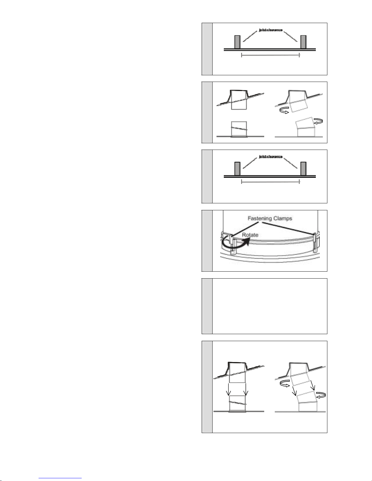
Step 1 Selecting the location for the diffuser in the ceiling
You will need a minimum clearance between joists of 275mm for the
Solatube 160DS, and 375mm for the Solatube 290DS (diagram A).
Ensure that no obstacles, pipes, wires or vent ducts are directly above
this location or potentially between the diffuser location and the roof
flashing position. If obstacles exist, move to a different location and
check again for clearance. Mark the position of the centre of the hole to
be cut and ensure you can locate it from within the roof void.
diagram A
275mm Ø hole for 160DS
375mm Ø hole for 290DS
Step 2 Selecting the location for the roof flashing
The roof flashing can be positioned either vertically above the diffuser
position or up to an angle of 30°from vertical in any direction from the
diffuser position by rotating the two angle adaptors supplied (diagram
B). The diagram shows two possible positions for the roof flashing
relative to the position of the top and bottom tube assemblies.
Note: 0-90°angle adaptors are available if a greater degree of variation
is required.
Cut a small hole in the roof felt and identify the roof position (tile) from
inside so you can locate it again later from the roof side.
diagram B
Step 3 Cutting the ceiling hole
Do not cut the ceiling hole until you are sure that the roof flashing will fit in
the desired location and that the top and bottom tube assemblies will
align.
Mark a 275mm circle for the 160DS or a 375mm circle for the 290DS
using your centre mark (from Step 1) as a centre point for the hole. Cut
the hole in the ceiling as marked (diagram C).
diagram C
cut 275mm Ø hole for 160DS
cut 375mm Ø hole for 290DS
Step 4 Installing the bottom tube assembly
Insert the bottom tube assembly up into the ceiling and, if the installation is
not vertical, rotate the angle adaptor to point towards the roof flashing
location. Using a crosshead screwdriver, rotate and tighten two of the
twist-lock fastening clamps to temporarily attach the bottom tube assembly
to the ceiling (diagram D). Do not remove the protective liner from the
inside of the bottom tube at this point.
diagram D
Step 5 Installing the roof flashing
To install the appropriate roof flashing for your roof type, please refer to
the roof flashing installation instructions that start on page 7.
The roof flashing is supplied according to the roof
type/flashing you specified on your order – please
ensure you have the correct roof flashing before
proceeding.
or
Step 6 Aligning the top tube assembly
Insert the top tube assembly into the roof flashing from the outside. For
metal roof flashings that have pre-drilled holes ensure the dome ring
screw holes are aligned with these pre-drilled holes. Non-metal flashings
do not have pre-drilled holes.
Manually screw one dome screw into the flashing through a pre-drilled
hole in the metal flashing or directly into a non-metal flashing to hold the
top tube assembly temporarily in place.
If necessary, rotate the angle adaptor so that the top tube assembly points
towards the bottom tube assembly in the ceiling. The lengths “L1” and “L2”
(diagram E) should be equal to ensure alignment.
Note: For flat roof/vaulted ceiling applications where no extension tubes
are required, the bottom tube assembly will be fitted up inside the top tube
assembly.
diagram E
L2
or
L2
L1 L1
4
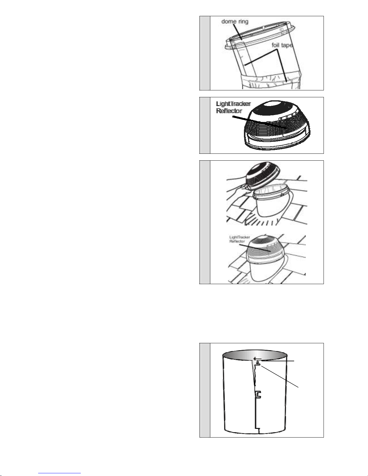
Step 7 Installing the top tube assembly
Unscrew the holding dome screw and remove the top tube assembly from
the roof flashing. Tape the angle adaptor joint and tube seams of the top
tube assembly with the foil tape provided (diagram F).
Remove the protective lining film from the inside of the tube and place the
top tube assembly back into the roof flashing, aligning it again with the
bottom tube assembly. Securely fasten the top tube assembly to the
flashing with the dome screws provided (into the pre-drilled holes in metal
flashings or directly into the upstand of non-metal flashings).
diagram F
Step 8 Inserting the LightTracker™ reflector in the dome
Using a magnetic compass if necessary, position the LightTracker™ dome
reflector in the north side of the dome, with the reflective side facing due
south. Align the holes in the reflector with the tabs inside the dome and
snap into place. Peel the protective film from the reflector (diagram G).
diagram G
Step 9 Installing the roof dome
Keeping the LightTracker™ on the north side of the dome facing south,
align the four tabs on the dome base with the snaps on the dome ring and
press down firmly to click into place. Check to make sure the snaps are
fully engaged (diagram H).
diagram H
Step 10 Connecting the top tube assembly to the bottom
tube assembly
For short installations with no extension tubes proceed to Step 12.
For longer installations with extension tubes continue to Step 11.
Step 11 Assembling extension tubes
Remove the protective liner from the extension tube(s) before assembly.
Extension tubes have deep and shallow notches at each end so that they
may be formed into slightly tapered tubes. Weave one end of the tube
through a deep notch, the other end through a shallow notch, ensuring the
tube is also held in the centre notch (diagram I). Tape the tube seam with
a short piece of foil tape at either end to hold the joints temporarily in
position. The smaller diameter tube end should always point towards the
bottom tube assembly. Assemble all the required extension tubes,
telescoping them together to provide the total length of tube required and
remembering to allow at least 50mm overlap at each join. At this stage,
use small pieces of foil tape to hold the tubes together. Check that the
assembled tube length is correct by holding the extension tube(s)
alongside the top and bottom tube assemblies. Adjust the tube length as
necessary.
For very long or angled tube lengths, self-tapping screws are provided to
fasten the extension tubes together. Tape all joints.
diagram I
shallow
notch
deep
notch
5
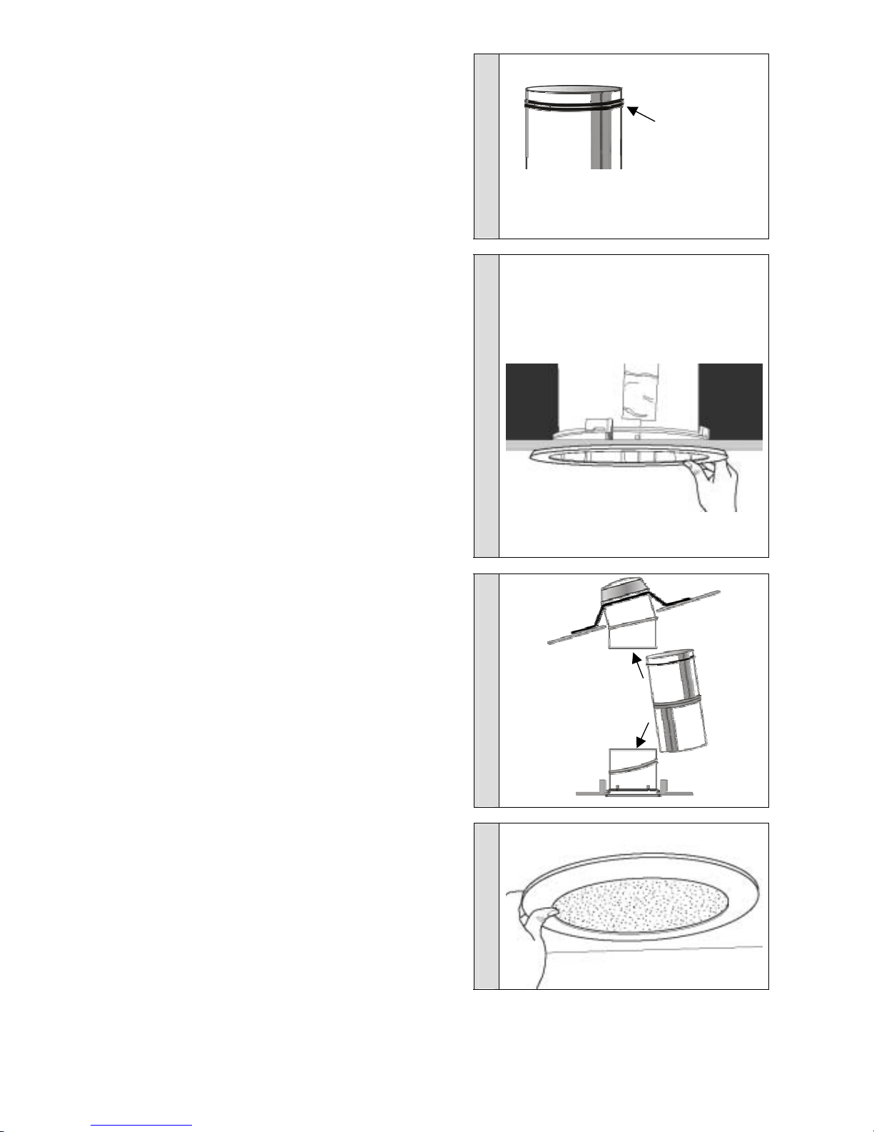
Step 12 Applying the expansion joint seal
For short installations with no extension tubes the expansion joint seal is
applied 25mm from the top edge of the bottom tube assembly.
For installations using extension tubes, the expansion joint seal is applied
25mm from the top edge of the uppermost extension tube.
The expansion joint seal should be applied to the outside diameter of the
tube in the following manner:
Remove the backing strip from the expansion joint seal and adhere it
25mm from the top edge of the tube. The seal should wrap twice around
the tube, not overlapping but butting up closely (diagram J).
diagram J
Step 13 Installing the bottom tube assembly
If any angle adjustment is required to the bottom tube assembly to align it
with the top tube assembly this should be done now; use a crosshead
screwdriver to loosen the twist-lock fastening clamps. Remove the
assembly from the ceiling, and rotate the angle adaptor if necessary to
ensure alignment with the top tube assembly.
If extension tubes are being used go to Step 14.
If no extension tubes are being used, re-insert the bottom tube
assembly, sliding it up into the top tube assembly and then lock all four
twist-lock fastening clamps into the ceiling (diagram K).
Note: If the ceiling clamps cannot be engaged owing to the thickness of
the ceiling or because of proximity to joists, the bottom tube assembly can
be screwed with the screws provided into the ceiling/joists through the pre-
drilled screw holes in the ceiling flange.
Do not over tighten the bottom tube assembly to the ceiling as this may
prevent fitting of the diffuser.
Remove the protective film from the inside of the bottom tube assembly.
diagram K
Step 14 Installing extension tubes
For installations with extension tubes, remove the protective film from
the inside of the bottom tube assembly and all other tubing if not already
done so. Re-insert the bottom tube assembly and then lock all twist-lock
fastening clamps into the ceiling.
Insert the extension tube with the expansion joint seal (a) up into the top
tube assembly. Then insert the other end (b) into the bottom tube
assembly (diagram L). Ensure there is a minimum 50mm overlap at either
end. Tape all joints together and use self tapping screws for additional
rigidity if necessary.
diagram L
expansion
joint seal
a
b
Step 15 – Diffuser installation
Align the diffuser to the bottom tube assembly. Apply firm upward
pressure on the white dress ring of the diffuser until it ‘snap fits’ into
position, taking care not to push on the central diffusing area (diagram M).
The diffuser is held in place by an interference fit in the bottom tube
assembly and can be removed if required by pulling down on the outside
of the white dress ring until it ‘snaps’ free.
diagram M
6
Brighten Up®Series installation guide
Solatube roof flashings
Please ensure you have the correct roof flashing before proceeding and read these instructions in conjunction with the
warnings, installation tips and safety advice on page 2.
These instructions cover typical applications. In some instances, roof tiles may need to be trimmed and roof structures
may be different to those described. Please contact your Solatube supplier before proceeding if you have any questions
regarding the installation of these roof flashings.
Flat roof
Page 8 Slate/plain tile
Page 9 Interlocking tile
Page 10
Solatube 160 DS and 290 DS Solatube 160 DS and 290 DS Solatube 160 DS and 290 DS
Single tile flashing
Page 11 Curb mount
Page 12 Turret extension
Page 12
Solatube 160 DS only Solatube 290 DS only Solatube 160 DS and 290 DS
7

Flat roof flashing
Parts list
Qty
Tile flashing 1
Flashing screws 50mm (in fastener kit) 8
Flashing screws 50mm (in flashing kit) 8
Geocel cartridge 1
First complete the Solatube 160DS or 290DS installation instructions Steps 1- 4
These flashing instructions cover a retrofit installation onto a felt roof. If the flat roof covering is being
installed at the same time as the Solatube, it is possible to install the Solatube roof flashing to the decking,
underneath the roofing material. Please refer to your Solatube supplier for more information.
Step A
Take the flashing, top tube assembly, tape, dome, LightTracker™, flashing screws, dome screws, Geocel and required
tools onto the roof.
Step B
Locate the centre point above the hole cut in the ceiling, and mark with a nail or screw. Sweep away any loose gravel
from the roof area where the flashing will be located. If the roof is felt or roll roofing, simply remove any dirt or loose
granules with a wire brush. If the roof is hot tarred and gravel, scrape away the embedded gravel and excess tar with a
flat or spud bar. The roof surface under the flashing and 75 mm beyond the edge must be smooth, level, clean and dry.
Step C
Drill eight 5mm diameter holes around the edge of the flashing
base between the eight existing holes (diagram 1).
diagram 1
Step D
Centre the flashing over the locating nail or screw. Mark the inside circumference onto the roof surface and the outer
edge of the flashing onto the roof to mark its final location. Remove the flashing and cut the inner circumference hole
through the roof deck, 20mm inside the inner marked line. Clean the sawdust from around the roof hole.
Step E
Apply a generous bead of Geocel sealant to the roof, 25mm
inside the perimeter of the outer edge flashing mark. Also apply a
generous bead of Geocel sealant on the underside of the
flashing, 25mm in from the outside edge (diagram 2).Lower the
flashing into its marked position and make sure that it is seated
correctly and the Geocel sealant has made a complete and
watertight seal.
diagram 2
Step F
Fasten the flashing to the roof with the 50mm flashing screws
provided. Screws should be firm, but not over tight (diagram 3).
Apply another bead of sealant to the outer edge of the flashing,
spreading it evenly to seal the flashing edge to the roof surface.
Apply sealant to all flashing screw heads. If the roof is a gravel
roof, sweep gravel back over the base of the flashing.
diagram 3
Please now continue to Step 6 of the Solatube 160DS or 290DS installation instructions
8
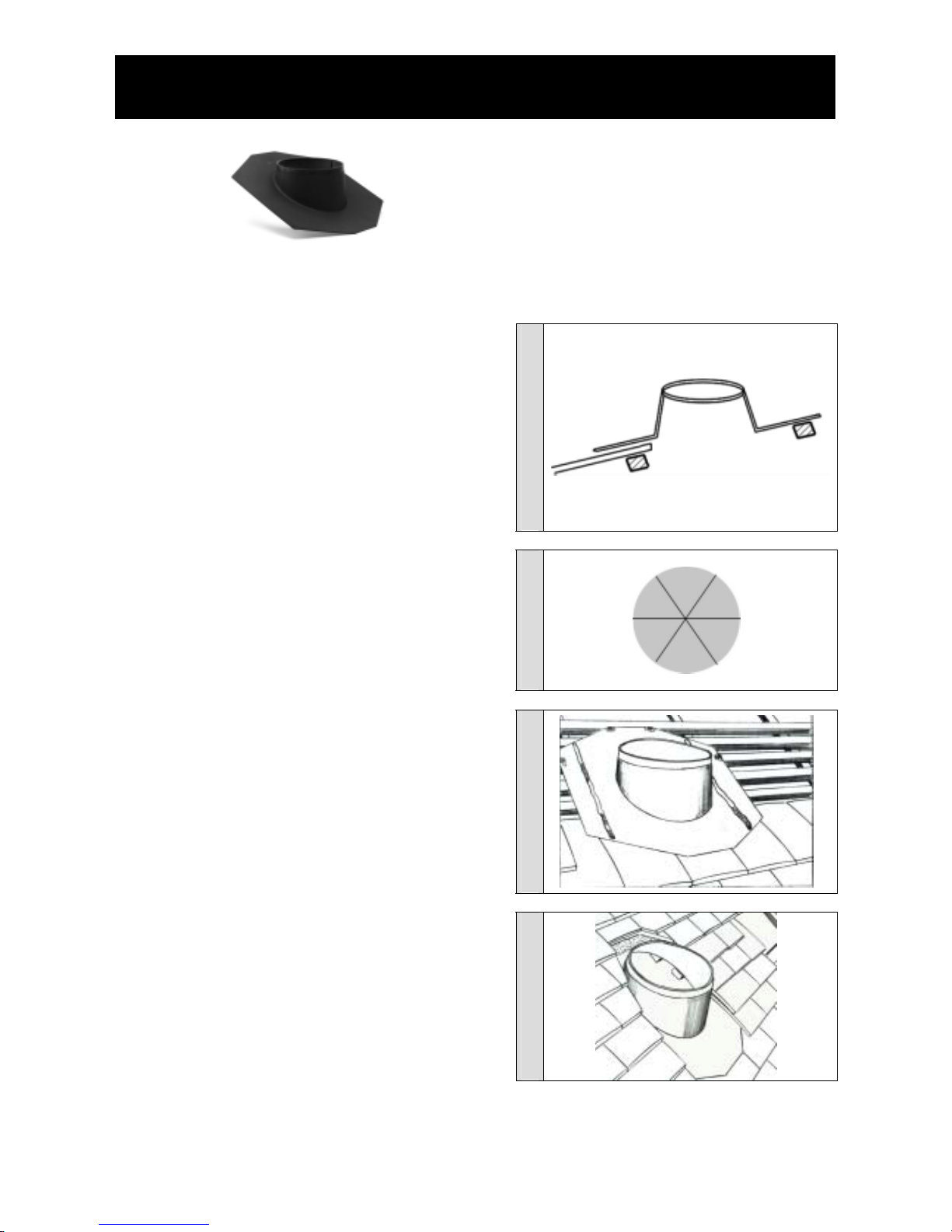
Slate and plain tile flashing
160DS flashing
Parts list
Qty
Tile flashing 1
Flashing screws 50mm (in fastener kit) 8
Flexseal cartridge 1
First complete the Solatube 160DS or 290DS installation instructions Steps 1- 4
Step A
Take the flashing, top tube assembly, tape, dome, flashing
screws, LightTracker™, dome screws, Flexseal and required
tools onto the roof.
Step B
Locate your marker and remove sufficient tiles to allow you to
place the top and aperture of the flashing onto the roof battens,
leaving sufficient tiles at the bottom edge to allow the flashing to
overlap sufficiently onto the tiles below. Double-check that no
rafters or obstructions lie behind the proposed tube position
(diagram 1). The tile pattern & size of tile will determine how
many tiles need to be replaced and/or cut to size.
diagram 1
Step C
Place the flashing to one side. Cutting obstructing battens if
necessary, cut through the roof felt in a star shape (diagram 2)
so the felt can be folded upwards and back on itself. Replace the
flashing over the hole and temporarily insert top tube into the
turret to check clearance and to angle the tube towards the
bottom tube assembly in the ceiling.
diagram 2
Step D
Using the flashing screws provided, secure the top of the flashing
to the appropriate batten and use a small amount of sealant to
cover each screw head. Apply a line of Flexseal sealant to the
side sections of the flashing onto which the tiles will be re-laid
(diagram 3).
diagram 3
Step E
Apply a line of Flexseal sealant at the bottom edge of the flashing
between the flashing and the tiles underneath, and across the top
edge of the flashing. Re-lay and fix the tiles to the sides and top
of the flashing ensuring there is a 40mm gap behind the flashing
upstand to allow the top tube assembly, dome ring and dome to
be inserted into the flashing upstand - note you may need to trim
the tiles to achieve this. Ensure all tiles are firmly in position and
the roof is fully watertight (diagram 4).
diagram 4
Please now continue to Step 6 of the Solatube 160DS or 290DS installation instructions
9

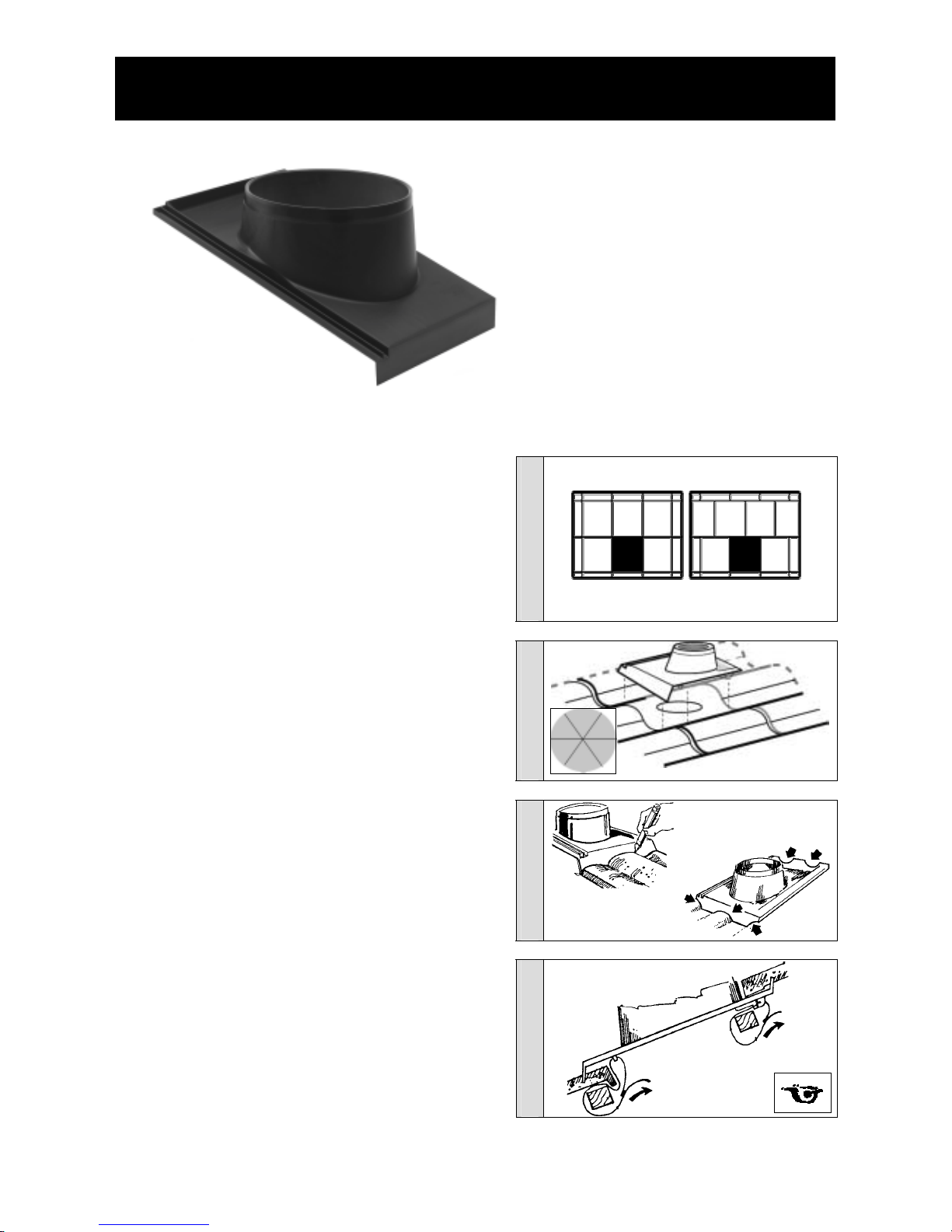
Interlocking tile flashing - universal
(picture shows offset flashing, parallel upstand flashing also available for low pitched roofs)
Parts list
Qty
Tile flashing (pitched or non-pitched version) 1
Aluminium ‘L’ brackets 4
6mm screws 8
Flashing screws 50mm (in fastener kit) 8
Note: Do not use Portland Cement based mastic, grout or
alkaline materials with this product. Caustic alkalis present in
fresh, unhardened mortar will attack the flexible aluminium
base.
First complete the Solatube 160DS or 290DS installation instructions Steps 1- 4
diagram 1
diagram 2
diagram 3
Step A
Take the flashing, top tube assembly, tape, dome, flashing
screws, LightTracker™, dome screws, and required tools onto
the roof.
Step B
Locate your marker and remove sufficient tiles to allow you to
place the top and aperture of the flashing onto the roof battens,
leaving sufficient tiles at the bottom edge to allow the flashing to
overlap sufficiently onto the tiles below. Double-check that no
rafters or obstructions lie behind the proposed tube position.
Using the flashing as a template, draw around the inside
circumference of the turret onto the roof felt (diagram 1).
Step C
Place the flashing to one side. Cutting obstructing battens if
necessary, cut the roof felt in a star shape (diagram 1) so the
felt can be folded upwards and back on itself. Replace the
flashing over the hole and temporarily insert top tube into the
turret to check clearance and to angle the tube towards the
bottom tube assembly in the ceiling.
Step D
Secure the top of the flashing to the roof battens using the
screws provided. Apply hand-pressure to form the bottom edge
of the flashing over the shape of the tiles beneath it. Turn up the
left and right edges of the flashing to ensure water cannot
ingress. (diagram 2).
Step E
Fix the aluminium ‘L’ brackets to secure the exposed lower end
of the flashing to the tiles (refer to the instructions supplied with
the ‘L’ brackets).
Replace and secure the removed tiles, ensuring a 40mm gap is
left behind the turret upstand to allow the top tube assembly,
dome ring and dome to be inserted into the flashing upstand –
note, you may need to trim the tiles to achieve this. Mould the
top of the flashing as necessary to fit the underside shape of the
tiles. Ensure all tiles are firmly in position and the roof is fully
watertight (diagram 3).
Please now continue to Step 6 of the Solatube 160DS or 290DS installation instructions
10
Interlocking tile flashing – single tile
Parts list
Qty
Tile flashing 1
Wire for fixing (not provided)
Note: This flashing replaces one complete
profiled or flat interlocking tile for tiles 300mm
visible width plus 30mm interlocking gully, total
width 330mm eg:
Redland: Grovebury, 50 Double Roman,
Regent, Renown
Marley: Ludlow major, Mendip, Double Roman,
Malvern
Alternatively use the interlocking tile flashing –
universal (page 10).
First complete the Solatube 160DS or 290DS installation instructions Steps 1- 4
Step A
Take the flashing, top tube assembly, tape, dome, dome screws,
flashing screws, LightTracker™, and required tools onto the roof.
Step B
Locate your marker and remove the tile to be replaced. Double-
check that no rafters or obstructions lie behind the proposed
tube position. You may also need to temporarily remove or slide
away the tiles above and to the left of the tile being replaced
(diagram 1).
diagram 1
ridge ridge
straight lay pattern offset pattern
Step C
Using the flashing as a template, draw around the inside
circumference of the turret onto the roof felt. Place the flashing to
one side. Cutting obstructing battens if necessary, cut the roof felt
in a star shape (diagram 2) so the felt can be folded upwards and
back on itself. Replace the flashing over the hole and temporarily
insert top tube into the turret to check clearance and to angle the
tube towards the bottom tube assembly in the ceiling.
diagram 2
Step D
The flashing skirt needs to be cut to the same profile as the tiles it
is sitting on (profiled or flat). Mark the profile of the lower roof tile
onto the front skirt of the flashing (and rear skirt if necessary).
Remove the flashing and file or cut the skirt along the line marked
so the flashing sits on the tiles below (and above if necessary)
with no gaps. Interlock the flashing to secure it into place
(diagram 3).
diagram 3
Step E
The flashing will be held in place by the weight of the tiles to the
left and behind, but the bottom right hand corner needs to be
secured. This is done by drilling through the lugs on the
underside of the flashing and wiring through the lugs and around
the closest batten (diagram 4). Ensure the flashing and tiles are
firmly in position and the roof is fully watertight.
diagram 4
Please now continue to Step 6 of the Solatube 160DS or 290DS installation instructions
11

Curb mount flashing
Parts list
Qty
Tile flashing 1
Geocel sealant 1
Flashing screws 50mm (in fastener kit) 8
First complete the Solatube 160DS or 290DS installation instructions Steps 1- 4
Step A
Take the flashing, top tube assembly, tape, dome, LightTracker™, flashing screws, dome screws, Geocel and required
tools onto the roof.
Step B
Centre the curb mounted flashing onto the pre-constructed or
manufactured curb. Check that flashing fits and that there are no
obstructions in the path of the tube (diagram 1). Allow sufficient
gap between the flashing and curb upstand for the roofing
material.
Run a generous line of Geocel sealant on the top of the curb
where it will make contact with the underside of the flashing to
seal. With the flashing screws provided, secure the sides of the
flashing into the curb upstand. Ensure the flashing is firmly in
position and the roof is fully watertight.
diagram 1
Please now continue to Step 6 of the Solatube 160DS or 290DS installation instructions
Turret extension
50mm turret extension shown – other sizes available please contact
your Solatube supplier for more details
Parts list
Qty
Turret extension 1
Geocel sealant 1
6mm screws 4
This procedure is for Solatube installations
where additional turret height is needed on
roof installation.
First complete the Solatube 160DS or 290DS installation instructions Steps 1- 5
Step A
Apply a bead of Geocel sealant around the outside of the top
edge of the flashing upstand. Place the turret extension over the
flashing upstand, aligning the pre-drilled holes and push down
until the inside of the turret extension contacts the top of the
flashing upstand (diagram 1). Fasten the turret extension to the
flashing upstand with the four 6mm screws. Ensure that the
Geocel sealant has made a watertight seal and remove any
excess Geocel sealant inside and outside the turret. Seal the
heads of the screws with Geocel sealant.
diagram 1
Please now continue to Step 6 of the Solatube 160DS or 290DS installation instructions
12
Other manuals for Energy Care Optima 160 DS
2
This manual suits for next models
1
Table of contents
Popular Inverter manuals by other brands


BARRON
BARRON EXITRONIX Tucson Micro Series installation instructions

Baumer
Baumer HUBNER TDP 0,2 Series Mounting and operating instructions

electroil
electroil ITTPD11W-RS-BC Operation and Maintenance Handbook

Silicon Solar
Silicon Solar TPS555-1230 instruction manual

Mission Critical
Mission Critical Xantrex Freedom SW-RVC owner's guide

HP
HP 3312A Operating and service manual


