Sourcetronic ST600 Series User manual
SOURCETRONIC – Quality electronics for service, lab and production
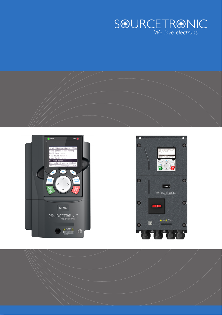
Frequency Inverter ST600 and ST600SP
Quick Start Guide

Quick Start Guide for ST600 Series Frequency Inverters Introduction
1
Introduction
This abridged manual briefly describes the external wiring, the terminals, the keypad, the quick start steps, as well
as the most common function parameter settings, errors and solutions and the most commonly used communica-
tion and PG cards for Sourcetronic ST600 and ST600SP series frequency inverters.
Visit www.sourcetronic.com for more information or refer to the detailed full version of the manual.
Warning!
This guide only contains the most basic information on installation and commissioning. Failure
to observe the safety instructions and the installation and commissioning instructions in the
corresponding documentation can lead to accidents, including damage to the appliance, inju-
ries or even death.
Only trained and qualified specialists may carry out the relevant work!
Danger!
Never carry out work such as wiring, inspection or replacement of components while the power
supply is switched on. Before carrying out this work, ensure that all input power supplies have
been disconnected and wait at least the time specified on the VFD (see below) or until the DC
bus voltage is less than 36 V.
VFD Model
Minimum Waiting Time
1R5G3–110G3
5 min
132G3-315G3
15 min
355G3 and above
25 min
Quick Start Guide for ST600 Series Frequency Inverters External Wiring
2
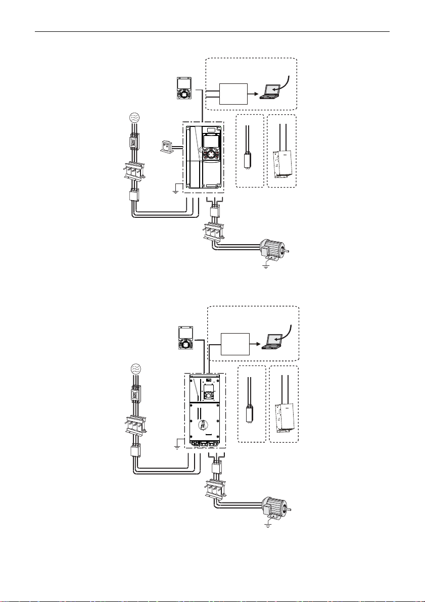
1External Wiring
Power supply
Breaker
Input filter
Input reactor
Earth
DC reactor
LCD keypad
P1
+
+-
PB
Brake
resistor Brake unit
PC
RS485–
RS232
converter
Output filter
Output reactor
Motor
Earth
+
Upper PC
software
485+
485-
Standard
Figure 1-1 ST600 System Configuration
Figure 1-2 ST600SP System Configuration
Power supply
Breaker
Input filter
Input reactor
Earth
LCD keypad
+-
PB
Brake
resistor Brake unit
PC
Adapter
(cable)
Output filter
Output reactor
Motor
Earth
+
Upper PC
software
485+
485-
Optional

Quick Start Guide for ST600 Series Frequency Inverters Terminals
3
2Terminals
Figure 2-1 Main Circuit Wiring for Standard Models
Figure 2-2 Main Circuit Wiring for SP Models
037G3 and lower
models
045G3 - 110G3
models
132G3 and higher
models
Braking resistor
Braking unit
Braking resistor
Braking resistor
Braking unit
Input
reactor
Input
filter
Fuse
Input
reactor
Input
filter
3PH power
380V(-15%)-440V(+10%)
50/60Hz
R
S
T
R
S
T
U
V
W
PE
U
V
W
PE
Output
reactor
Output
filter
M
(+) (-)
P1
(+) (-)
PB
Fuse
Fuse
Input
reactor
Input
filter
R
S
T
U
V
W
PE
Output
reactor
Output
filter
Output
reactor
Output
filter
M
M
(+) (-)
DC+
DC-
DC+
DC-
DC reactor
3PH power
380V(-15%)-440V(+10%)
50/60Hz
3PH power
380V(-15%)-440V(+10%)
50/60Hz
All models
Braking resistor
Input
reactor
Input
filter
Fuse
3PH power
380V(-15%)-440V(+10%)
50/60Hz
R
S
T
U
V
W
PE
Output
reactor
Output
filter
M
(+) (-)
PB

Quick Start Guide for ST600 Series Frequency Inverters Terminals
4
+24V
PE
COM
S4
S3
S2
S1
HDIB
PW
HDIA
Forward running
Forward jogging
Fault reset
+10V
AI1
AI2
GND
PE
-10V
(external)
AO1
V I
SW2
GND
Analog output
0-10V/0-20mA
Y1
CME
COM
HDO
Optional between high-
speed pulse output and
open collector output
485+
485-
PE
RS485
communication
RO2C
RO2B
RO2A
RO1C
RO1B
RO1A
Relay 1
output
Relay 2
output
ON OFF
SW3
multi-function
analog input
H1
H2
+24V
S2
S1
Safety
controller
Open circuit
Safety
input
Safety
switch
Y1
output
Safety state
feedback
Power used for
frequency setting
VFD
Figure 2-3 Control Circuit Wiring
Quick Start Guide for ST600 Series Frequency Inverters Terminals
5
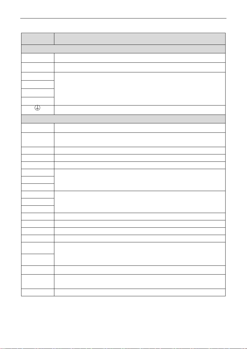
Table 2-1 VFD Terminal Description
Terminal
Description
Main Circuit Terminals
R, S, T
3PH AC input terminals, connected to the grid
U, V, W
3PH AC output terminals, usually connected to the motor
P1
P1 and (+) connect to external DC reactor terminals.
(+) and (-) connect to external braking unit terminals or shared DC bus terminals.
PB and (+) connect to external braking resistor terminals.
(+)
(-)
PB
PE terminal. The PE terminals of each machine must be grounded reliably.
Control Circuit Terminals
+10V
Locally provided +10.5V power supply
AI1
Analog input. Range: 0–10V/0–20mA. Function code P05.50 specifies whether to use voltage or
current input.
AI2
Analog input. Range: -10V – +10V
GND
Reference ground of +10.5V
AO1
Analog output. Range: 0–10V/0–20mA. SW2 is used to select voltage or current output.
RO1A
Relay output. RO1A: NO; RO1B: NC; RO1C: common
Contact capacity: 3A/AC 250V, 1A/DC 30V
RO1B
RO1C
RO2A
Relay output. RO2A: NO; RO2B: NC; RO2C: common
Contact capacity: 3A/AC 250V, 1A/DC 30V
RO2B
RO2C
HDO
Switch capacity: 50mA/30V. Output frequency range: 0–50kHz. Duty ratio: 50%
COM
Reference ground of +24V
CME
Common terminal of open collector output; short connected to COM by default
Y1
Switch capacity: 50mA/30V; Output frequency range: 0–1kHz
485+
RS485 differential signal communication port. The standard communication interface should use a
shielded twisted pair cable. Specify whether the 120 Ω matching resistor of the RS485 communi-
cation should be connected via the DIP switch or the jumper.
485-
PE
Grounding terminal
PW
External power input terminal for digital input circuits. In NPN mode, short-circuit PW and +24V. In
PNP mode, short-circuit PW and COM.
+24V
User the power supply provided by the VFD. Max. output current: 200mA

Quick Start Guide for ST600 Series Frequency Inverters Terminals
6
S1–S4
Digital Input:
Internal impedance: 3.3kΩ
12–30V voltage input is acceptable
Bidirectional input terminals, supporting both NPN and PNP connection methods
Max. input frequency: 1kHz
Programmable digital input terminals, the exact functions of which can be set via related
parameters
HDIA
Channels for Both High Frequency Pulse Input and Digital Input:
Max. input frequency: 50kHz
Duty ratio: 30%–70%
Supports quadrature encoder input when both HDIA and HDIB are available, with the speed
measurement function
HDIB
+24V–H1
Safe Torque Off (STO) Inputs:
Redundant STO input, connected to the external NC contact. When the contact opens, STO
is activated and the VFD stops the output.
Shielded cables with a maximum length of 25m are used for the safety input signal cables.
Terminals H1 and H2 are short-circuited to +24 V by default. Remove the jumper from the
terminals before using the STO function.
+24V–H2
Quick Start Guide for ST600 Series Frequency Inverters Keypad
7
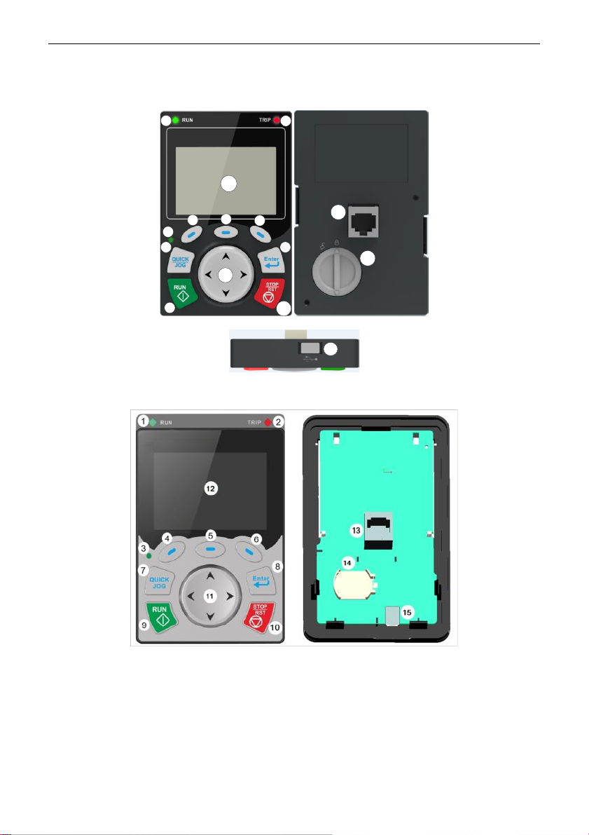
3Keypad
The specifics of the keypad may vary between product models.
12
7
456
11
8
910
12
3
13
14
15
Figure 3-1 Standard Model Keypad
Figure 3-2 SP Model Keypad

Quick Start Guide for ST600 Series Frequency Inverters Keypad
8
No.
Name
Description
1
State
Indicators
Operation Indicator:
LED off – the VFD is stopped;
LED on – the VFD is running
LED blinking – the VFD is in parameter autotuning
2
Error Indicator:
LED on – the VFD is in error state
LED off – the VFD is in normal state
LED blinking – the VFD is in pre-alarm state
3
Short-cut key indicator, which displays different state under different functions,
see definition of QUICK/JOG key for details
4
Function Keys
The function of the function key depends on the respective menu.
The function of the function key is displayed in the footer.
5
6
7
Shortcut Key
Custom. By default, the button is defined as the JOG function. The function of
the shortcut button can be set via P07.02, as shown below.
0: No function;
1: Jogging (linkage indicator (3); logic: NO);
2: Reserved;
3: Switch between FWD and REV (linkage indicator (3); logic: NC);
4: Clear UP/DOWN settings (linkage indicator (3) logic: NC);
5: Coast to stop (linkage indicator (3); logic: NC);
6: Switch the operating command reference value mode in sequence (linkage
indicator (3); logic: NC);
7: Reserved;
Note: If default values are restored, the set function of the shortcut key returns
to 1 (jogging).
8
Confirmation Key
The function of the confirmation button varies depending on the menu, e.g. con-
firmation of parameter setting, confirmation of parameter selection, calling up the
next menu, etc.
9
Running Key
In keypad operation mode, this button is used to start VFD operation or to initiate
autotuning.
10
Stop/Reset Key
During operation, you can stop the VFD or stop the autotuning by pressing the
Stop/Reset button; this button is limited by the setting of P07.04. While in error
state, all control modes can be reset with this button.

Quick Start Guide for ST600 Series Frequency Inverters Keypad
9
11
Direction Keys
UP: The function of the UP key varies depending on the interface, e.g. moving
the displayed element upwards, moving the selected element upwards, changing
digits, etc;
DOWN: The function of the DOWN key varies depending on the interface, e.g.
moving the displayed element downwards, moving the selected element down-
wards, changing digits, etc;
LEFT: The function of the LEFT key varies depending on the interface, e.g.
switching the monitoring interface, e.g. moving the cursor to the left, exiting the
current menu and returning to the previous menu, etc;
RIGHT: The function of the RIGHT key varies depending on the interface, e.g.
switching the monitoring interface, moving the cursor to the right, calling up the
next menu, etc.
12
Screen Display
240×160 dot-matrix LCD; able to display three monitoring parameters or six sub-
menu items simultaneously
13
RJ45 Interface
You can use the RJ45 interface to connect to the VFD.
14
Clock Battery Holder
You can use the battery holder for replacing or installing a battery for the clock.
15
USB Terminal
Mini USB terminal
Quick Start Guide for ST600 Series Frequency Inverters Quick Start
10
4Quick Start
4.1 Check Before Power-On
Ensure that all terminals have been securely connected.
Ensure that the motor power matches the VFD power.
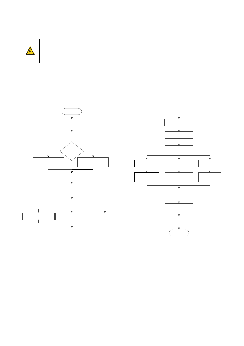
4.2 First Operation
Make sure the wiring and power supply are correct and close the AC power supply air switch on the VFD input
side to turn on the device. The LCD user interface will launch the setup wizard to guide you through the setup.
The quick start flowchart is as follows:
Start
Power on after the wiring
is connect ed properly
Restore to default values
Set the motor param et ers
(P02.01–P02.05) as per
the mot or nam eplate
Set the motor param et ers
(P02.15–P02.19) as per
the mot or nam eplate
Press QUICK/ JOG to start
pilot run
If the mot or rotates in an
incorrect direction, power off and
exchange the motor wires of any
two phases, and power on again
Set autotuning mode
(P00.15)
Press RUN to start
autotuning (Aut omatical ly
stop once finished)
Asynchronous
mot or (AM)
Synchronous
mot or (SM)
Mot or
select ion
P02.00 or
P12.00
…
Set running frequency
(P00.06)
Set speed running
control mode (P00.00)
SVC 0 (P00.00=0) SVC 1 (P00.00=1) SVPWM (P00.00=2)
Set vector cont rol
param et ers in P03
group
Set vector cont rol
param et ers in P03
group
Set V/ F param et ers
in P04 group
Set start/stop control
param et ers in P01
group
Give the running
comm and to run
Give the stop
comm and to stop
Set running command
channel (P00.01, P00.02)
Set P00.15=2 to perform
static aut otuning 1
Set P00.15=3 to perform
static aut otuning 2
Set P00.15=1 to perform
rotary autotuning
End

Quick Start Guide for ST600 Series Frequency Inverters Important Function Parameter Settings
11
5Important Function Parameter Settings
Only a few common function parameters and typical values are briefly described below.
"○" indicates that the value of the parameter can be changed when the VFD is in stop or operating mode.
"◎" indicates that the value of the parameter cannot be changed while the VFD is in operation.
"●" indicates that the value of the parameter is recognized and saved, but cannot be changed.
(The VFD automatically checks parameter changes and restricts them to prevent invalid settings.)
Function
Code
Name
Description
Default
Modifiable?
P00.00
Speed Control Mode
0: Sensorless vector control (SVC) mode 0
1: Sensorless vector control (SVC) mode 1
2: Space voltage vector control mode
3: Closed-loop vector control mode
2
◎
P00.01
Channel Of Running
Commands
0: Keypad
1: Terminal
2: Communication
0
○
P00.02
Communication Mode Of
Running Commands
0: Modbus/Modbus TCP
1: PROFIBUS/CANopen/DeviceNet
2: Ethernet
3: EtherCAT/PROFINET/ Ethernet IP
4: Programmable expansion card
5: Wireless communication card
6: Reserved
Note: The options 0 (for Modbus TCP), 1, 2, 3, 4
and 5 are add-on functions, valid only when config-
ured with related expansion cards.
0
○
P00.03
Max. Output Frequency
Max (P00.04; 10)–630.00Hz
50.00Hz
◎
P00.04
Upper Limit Of Running
Frequency
P00.05–P00.03 (Max. output frequency)
50.00Hz
◎
P00.05
Lower Limit Of Running
Frequency
0.00Hz–P00.04 (Upper limit of running frequency)
0.00Hz
◎
P00.06
Channel to Set
Frequency Reference
Value A
0: Keypad
1: AI1
2: AI2
3: AI3
0
○
Quick Start Guide for ST600 Series Frequency Inverters Important Function Parameter Settings
12
P00.07
Channel to Set
Frequency Reference
Value B
4: High-speed pulse HDIA
5: Simple PLC program
6: Multi-step speed running
7: PID control
8: Modbus/Modbus TCP communication
15
○
P00.10
Frequency Set
Through Keypad
0.00 Hz–P00.03 (Max. output frequency)
50.00Hz
○
P00.11
ACC Time 1
0.0–3600.0s
Model-
dependent
○
P00.12
DEC Time 1
Model-
dependent
○
P00.13
Running Direction
0: Run forward
1: Run backward (reverse)
2: Disable reverse running mode
0
○
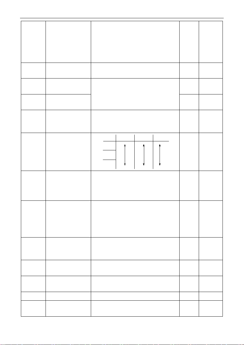
P00.14
Carrier Frequency
Carrier
frequency
Electromagnet ic
noise
Noise and
leakage current
Heat
dissipation
1kHz
10kHz
15kHz
High
Low
Low
High
Low
High
Model-
dependent
○
P00.15
Motor Parameter
Autotuning
0: Disable
1: Rotary autotuning 1
2: Static autotuning 1 (full)
3: Static autotuning 2 (partial)
0
◎
P00.18
Restore Function
Parameters
0: Disable
1: Restore defaults (excluding motor parameters)
2: Clear error records
5: Restore defaults (factory test mode)
6: Restore defaults (including motor parameters)
0
◎
P01.00
Start Mode
0: Direct start
1: Start after DC braking
2: Start after speed tracking
0
◎
P01.08
Stop Mode
0: Decelerate to stop
1: Coast to stop
0
○
P01.09
Starting Frequency Of
DC Braking For Stop
0.00Hz–P00.03 (Max. output frequency)
0.00Hz
○
P01.11
DC Braking Current
0.0–100.0%
0.0%
○
P01.12
DC Braking Time
Until Standstill
0.00–50.00s
0.00s
○

Quick Start Guide for ST600 Series Frequency Inverters Important Function Parameter Settings
13
P01.18
Terminal-Based
Operating Command
Protection At Power-On
0: Terminal-based operating commands are in-
active at power-on
1: Terminal-based operating commands are active
at power-on
0
◎
P02.00
Type Of Motor 1
0: Asynchronous motor (AM)
1: Synchronous motor (SM)
0
◎
P02.01
Rated Power Of AM 1
0.1–3000.0kW
Model-
dependent
◎
P02.02
Rated Frequency Of
AM 1
0.01Hz–P00.03 (Max. output frequency)
50.00Hz
◎
P02.03
Rated Speed Of AM 1
1–60000rpm
Model-
dependent
◎
P02.04
Rated Voltage Of AM 1
0–1200V
Model-
dependent
◎
P02.05
Rated Current Of AM 1
0.8–6000.0A
Model-
dependent
◎
P02.15
Rated Power Of SM 1
0.1–3000.0kW
Model-
dependent
◎
P02.16
Rated Frequency Of
SM 1
0.01Hz–P00.03 (Max. output frequency)
50.00Hz
◎
P02.17
Number Of Pole Pairs
Of SM 1
1–128
2
◎
P02.18
Rated Voltage Of SM 1
0–1200V
Model-
dependent
◎
P02.19
Rated Current Of SM 1
0.8–6000.0A
Model-
dependent
◎
P02.23
Counter-Emf Of SM 1
0–10000
300
○
P03.00
Speed-Loop
Proportional Gain 1
0.0–200.0
20.0
○
P03.01
Speed-Loop Integral
Time 1
0.000–10.000s
0.200s
○
P03.03
Speed-Loop
Proportional Gain 2
0.0–200.0
20.0
○
P03.04
Speed-Loop Integral
Time 2
0.000–10.000s
0.200s
○

Quick Start Guide for ST600 Series Frequency Inverters Important Function Parameter Settings
14
P03.09
Current-Loop
Proportional
Coefficient P
0–65535
1000
○
P03.11
Torque Setting Method
0–1: Keypad (P03.12)
2: AI1
3: AI2
4: AI3
5: Pulse frequency HDI
6: Multi-step torque
7: Modbus communication
0
○
P04.01
Torque Boost Of Motor 1
0.0%: (Automatic torque boost), 0.1%–10.0%
0
○
P04.09
V/F Slip Compensation
Gain Of Motor 1
0.0–200.0%
100.0%
○
P04.10
Low-Frequency
Oscillation Control
Factor Of Motor 1
0–100
10
○
P04.11
High-Frequency
Oscillation Control
Factor Of Motor 1
0–100
10
○
P05.01
Function Of S1
0: No function
1: Run forward
2: Run backward
3: Three-wire operating control (SIN)
4: Jog forward
5: Jog backward
6: Coast to stop
7: Reset errors
9: External error input
10: Increase frequency setting (UP)
11: Decrease frequency setting (DOWN)
1
◎
P05.02
Function Of S2
4
◎
P05.03
Function Of S3
7
◎
P05.04
Function Of S4
0
◎
P05.29
AI2 Lower Limit
-10.00V–P05.31
-10.00V
○
P05.35
AI2 Upper Limit
P05.33–10.00V
10.00V
○
P06.01
Y1 Output
0: Inactive
1: Running
2: Running forward
3: Running backward
4: Jogging
5: VFD in error
6: Frequency level detection FDT1
8: Frequency reached
0
○
P06.03
RO1 Output
1
○
P06.04
RO2 Output
5
○

Quick Start Guide for ST600 Series Frequency Inverters Important Function Parameter Settings
15
P06.14
AO1 Output
0: Operating frequency
1: Set frequency
3: Rotation speed (Relative to the speed corre-
sponding to max. output frequency )
4: Output current (Relative to twice the VFD rated
current)
5: Output current (Relative to twice the motor rated
current)
6: Output voltage (Relative to 1.5 times the VFD
rated voltage)
7: Output power (Relative to twice the motor rated
power)
0
○
P06.16
HDO High-Speed Pulse
Output
0
○
P06.17–
P06.21
AO1 Output
Upper/Lower Limit
Settings
For details, see the full version of the e-manual.
○
P07.00
User Password
0–65535
0
○
P07.27–
P07.32
Present Error Type –
5th-Last Error Type
0–76
(0: No error)
For details, see the full version of the e-manual.
0
○
P08.28
Auto Error Reset Count
0–10
0
○
P08.29
Auto Error Reset Interval
0.1–3600.0s
1.0s
○
P14.00
Local Communication
Address
1–247
Note: The communication address of a slave can-
not be set to 0.
1
○
P14.01
Communication Baud
Rate
0: 1200BPS
1: 2400BPS
2: 4800BPS
3: 9600BPS
4: 19200BPS
5: 38400BPS
4
○
P14.02
Data Bit Check
0: No check (N, 8, 1) for RTU
1: Even check (E, 8, 1) for RTU
2: Odd check (O, 8, 1) for RTU
3: No check (N, 8, 2) for RTU
4: Even check (E, 8, 2) for RTU
5: Odd check (O, 8, 2) for RTU
1
○
P15.01
Module Address
0–127
2
○
P15.02–
P15.12
Received Pzd2–
Received Pzd12
0–31
1: Set frequency (0–Fmax, unit: 0.01Hz)
0
○

Quick Start Guide for ST600 Series Frequency Inverters Important Function Parameter Settings
16
and
P16.32–
P16.42
2: PID reference (-1000–1000, in which 1000 corre-
sponds to 100.0%)
3: PID feedback (-1000–1000, in which 1000 corre-
sponds to 100.0%)
4: Torque setting (-3000–+3000, in which 1000 cor-
responds to 100.0% of the motor rated current)
5: Upper limit of the FWD operating frequency (0–
Fmax, unit: 0.01 Hz)
6: Upper limit of the REV operating frequency (0–
Fmax, unit: 0.01 Hz)
7: Upper limit of the electromotive torque (0–3000,
in which 1000 corresponds to 100.0% of the motor
rated current)
8: Upper limit of the braking torque (0–3000, in
which 1000 corresponds to 100% of the motor rated
current)
P15.13–
P15.23
and
P16.43–
P16.53
Sent Pzd2–Sent Pzd12
0–31
1: Operating frequency (x100, Hz)
4: Output voltage (x1, V)
5: Output current (x10, A)
6: Actual output torque (x10, %)
7: Actual output power (x10, %)
8: Rotation speed (x1, RPM)
0
○
P20.00
Encoder Type Display
0: Incremental encoder
1: Resolver-type encoder
2: Sin/Cos encoder
3: Endat absolute encoder
0
●
P20.01
Encoder Pulse Number
0–16000
1024
◎
P20.02
Encoder Direction
0x000–0x111
Ones digit: AB direction
0: Forward
1: Reverse
Tens digit: Z pulse direction (reserved)
0: Forward
1: Reverse
Hundreds digit: CD/UVW pole signal direction
0: Forward
1: Reverse
0x000
◎
P20.03
Detection Time Of
Encoder Offline Error
0.0–10.0s
2.0s
○

Quick Start Guide for ST600 Series Frequency Inverters Possible Errors and Solutions
17
6Possible Errors and Solutions
Note: Our error code scheme is being upgraded. Some products use the old scheme and the others use the new
one, which are listed in "Error code display".
Error
Code
Error Type
Possible Cause
Corrective Measures
OUt1
[1] Inverter Unit U Phase
Protection
Acceleration is too fast;
IGBT module is damaged;
Malfunction due to interference; wires
are poorly connected;
To-ground short-circuit occurred
Increase acceleration time;
Replace the power unit;
Check the wires;
Check for sources of strong interfer-
ence in the vicinity of the peripheral
device
OUt2
[2] Inverter Unit V Phase
Protection
OUt3
[3] Inverter Unit W
Phase Protection
OC1
[4] Overcurrent During
Acceleration
Acceleration is too fast;
Grid voltage is too low;
VFD power is too small;
Load transient or exception occurred;
To-ground short-circuit or output
phase loss occured;
Strong external interference;
Overvoltage stalling protection is not
enabled
Increase the ACC/DEC time;
Check the input power;
Select a VFD with larger power;
Check if the load is short-circuited (to-
ground short-circuit or line-to-line
short-circuit) or the rotation is not
smooth;
Check the output wiring;
Check for sources of strong interfer-
ence;
Check the setup of related function
codes.
OC2
[5] Overcurrent During
Deceleration
OC3
[6] Overcurrent During
Constant Speed
Running
OV1
[7] Overvoltage During
Acceleration
Deceleration is too short;
Exception occurred at the input volt-
age;
Large energy feedback;
Lack of braking units;
Dynamic braking is not enabled, and
the deceleration time is too short.
Check the input power;
Check if the load deceleration time is
too short; or if the motor starts up dur-
ing rotation;
Install dynamic braking units;
Check the settings of related function
codes
OV2
[8] Overvoltage During
Deceleration
OV3
[9] Overvoltage During
Constant Speed
UV
[10] Bus Undervoltage
Error
Grid voltage is too low;
Overvoltage stalling protection is not
enabled
Check the grid input power;
Check the setup of related function
codes
OL1
[11] Motor Overload
Grid voltage is too low;
Rated motor current is set incorrectly;
The motor stalls, or the load jumps vi-
olently
Check the grid voltage;
Reset the rated motor current;
Check the load and adjust the torque
boost
OL2
[12] VFD Overload
Acceleration is too fast;
Increase acceleration time;

Quick Start Guide for ST600 Series Frequency Inverters Possible Errors and Solutions
18
The motor restarts during rotation;
Grid voltage is too low;
Load is too large;
Power is too low;
Avoid restart after stop;
Check the grid voltage;
Select a VFD with larger power;
Select a suitable motor
SPI
[13] Phase Loss On
Input Side
Phase loss or intense fluctuation oc-
curred to R, S and T input
Check the input power;
Check installation wiring
SPO
[14] Phase Loss On
Output Side
Phase loss occurred to U, V, W output
(or the three phases of the motor are
asymmetrical)
Check the output wiring;
Check the motor and cable
OH1
[15] Rectifier Module
Overheating
Air duct is blocked or fan is damaged;
Ambient temperature is too high;
Long-term overload
Ventilate the air duct or replace the
fan;
Lower the ambient temperature
OH2
[16] Inverter Module
Overheating
CE
[18] Modbus/Modbus
TCP Communication
Error
Baud rate is set incorrectly;
Communication line error;
Communication address error;
Communication suffers from strong in-
terference
Set a suitable baud rate;
Check the wiring of communication
interfaces;
Set a suitable communication ad-
dress;
Replace or change the wiring to im-
prove anti-interference capacity
tE
[20] Motor Autotuning
Error
Motor capacity does not match with
the VFD capacity, this error may occur
easily if the difference between them
is exceeds five power classes;
Motor parameters are set incorrectly;
The parameter settings obtained via
autotuning deviate sharply from the
standard standards;
Autotuning timeout
Select a different VFD model, or ena-
ble V/F control mode;
Set the correct motor type and name-
plate parameters;
Empty the motor load and restart au-
totuning;
Check the motor wiring and parame-
ter setup;
Check whether the frequency upper
limit is larger than 2/3 of the rated fre-
quency
dEu
[34] Speed Deviation
Error
Load is too heavy, or stalling occurred
Check the load to ensure it is suitable,
increase the detection time;
Ensure that the control parameters
are set correctly
STo
[35] Maladjustment Error
Control parameters of synchronous
motor is set improperly;
The parameter settings obtained via
autotuning are inaccurate;
Check the load to ensure it is suitable,
Ensure that the control parameters
are set correctly;

Quick Start Guide for ST600 Series Frequency Inverters Possible Errors and Solutions
19
The VFD is not connected to the motor
Increase the maladjustment detection
time
Other manuals for ST600 Series
1
This manual suits for next models
46
Table of contents
Other Sourcetronic Inverter manuals


