TRISKEL MARINE integrel User manual

TRAINING AND
INSTALLATION GUIDE
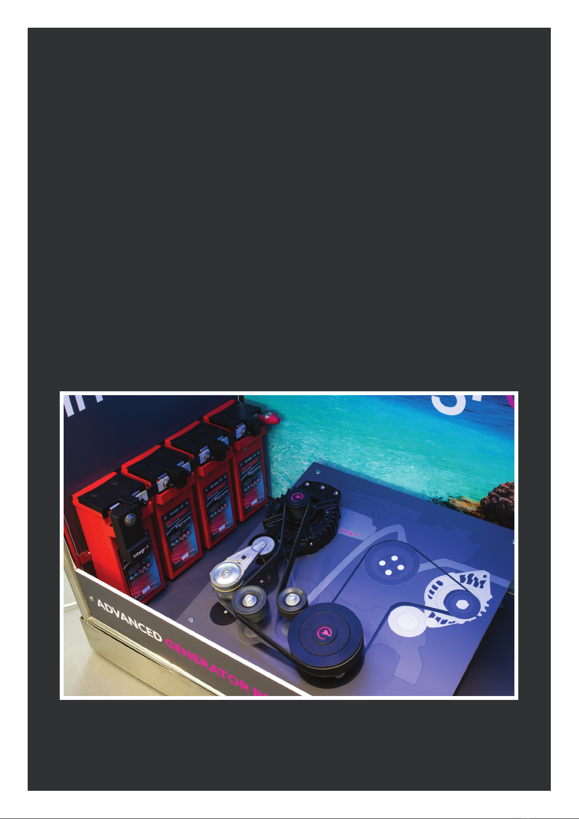
ADVANCED GENERATOR REPLACEMENT TECHNOLOGY

Please Note
Integrel is classified as an “extra low voltage DC system” and falls
within the scope of the international standard ISO 10133:2017
and ABYC E11. It is strongly recommended that a copy of these
standards is studied before proceeding with the installation of
the Integrel system. Nothing in this guide supersedes these two
standards and if conflicting information is found, the standards
will always prevail.
Target Audience Assumptions
It is assumed that the reader of this installation guide is a trained
electrical installer with an adequate knowledge of marine electrical
engineering terms, concepts, language and abbreviations.
ADVANCED GENERATOR REPLACEMENT TECHNOLOGY
IMPORTANT SAFETY INSTRUCTIONS. Electromechanical
equipment, including generator sets, transfer switches,
switchgear, and accessories, can cause bodily harm and pose
life-threatening danger when improperly installed, operated, or
maintained. To prevent accidents be aware of potential dangers
and act safely. Read and follow all safety precautions and
instructions. SAVE THESE INSTRUCTIONS.
This manual has several types of safety precautions and
instructions: Danger, Warning, Caution, and Notice.
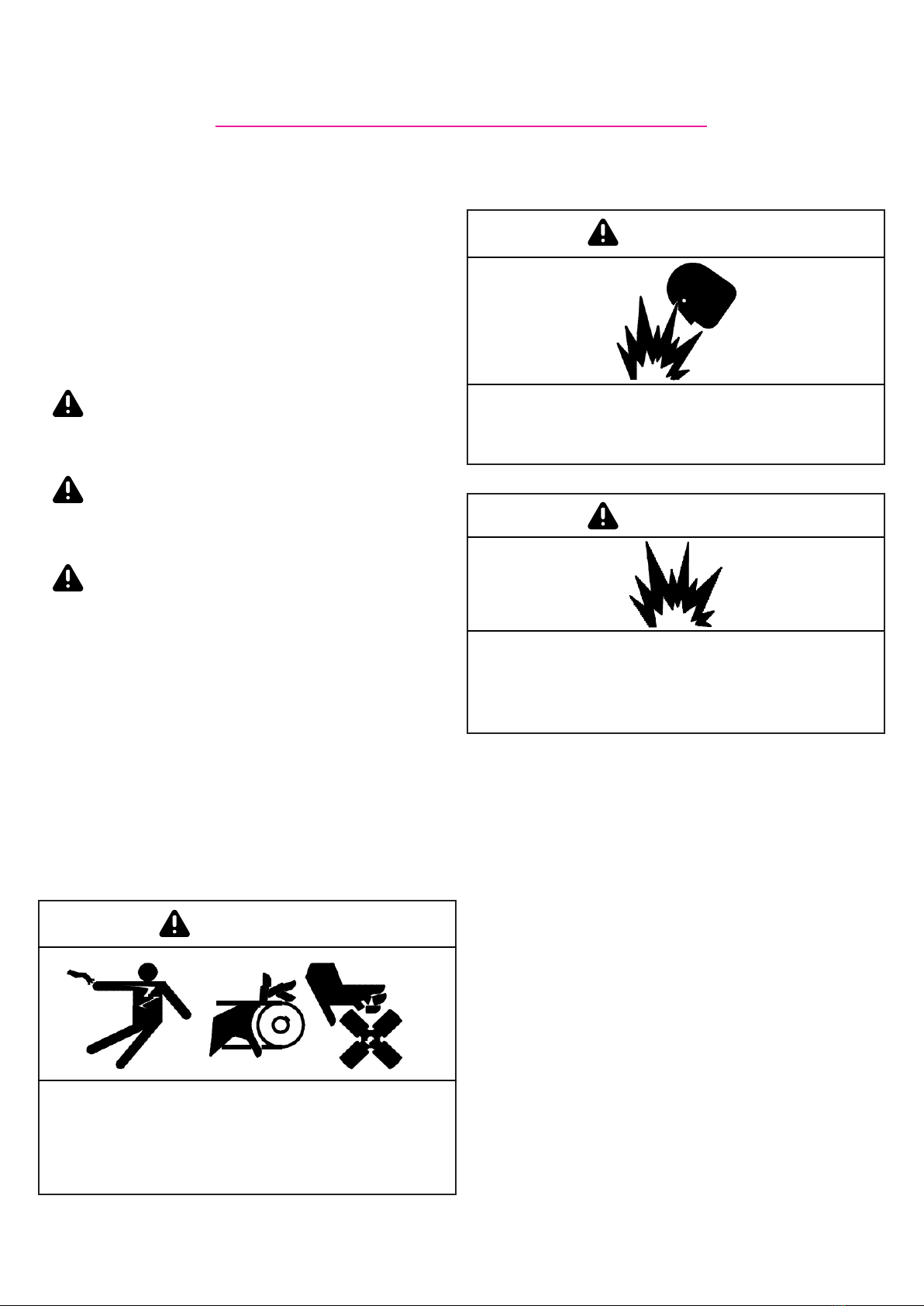
DANGER
Danger indicates the presence of a hazard that will cause severe
personal injury, death, or substantial property damage.
WARNING
Warning indicates the presence of a hazard that can cause
severe personal injury, death, or substantial property damage.
CAUTION
Caution indicates the presence of a hazard that will or can
cause minor personal injury or property damage.
NOTICE
Notice communicates installation, operation, or maintenance
information that is safety related but not hazard related.
Safety decals affixed to the equipment in prominent places
alert the operator or service technician to potential hazards and
explain how to act safely. The decals are shown throughout this
publication to improve operator recognition. Replace missing or
damaged decals.
Accidental Starting
WARNING
Accidental starting. Can cause severe injury or death.
Disconnect the battery cables before working on the generator
set. Remove the negative (-) lead first when disconnecting the
battery. Reconnect the negative (-) lead last when reconnecting
the battery.
Battery Safety
WARNING
Sulfuric acid in batteries. Can cause severe injury or death.
Wear protective goggles and clothing. Battery acid may cause
blindness and burn skin.
WARNING
Explosion. Can cause severe injury or death. Relays in the
battery charger cause arcs or sparks.
Locate the battery in a well-ventilated area. Isolate the battery
charger from explosive fumes.
Battery gases. Explosion can cause severe injury or death.
Battery gases can cause an explosion. Do not smoke or permit
flames or sparks to occur near a battery at any time, particularly
when it is charging. Do not dispose of a battery in a fire. To
prevent burns and sparks that could cause an explosion, avoid
touching the battery terminals with tools or other metal objects.
Remove all jewellery before servicing the equipment. Discharge
static electricity from your body before touching batteries by
first touching a grounded metal surface away from the battery.
To avoid sparks, do not disturb the battery charger connections
while the battery is charging. Always turn the battery charger
off before disconnecting the battery connections. Ventilate the
compartments containing batteries to prevent accumulation of
explosive gases.
Battery short circuits. Explosion can cause severe injury
or death. Short circuits can cause bodily injury and/or
equipment damage. Disconnect the battery before generator
set installation or maintenance. Remove all jewellery before
servicing the equipment. Use tools with insulated handles.
Remove the negative (-) lead first when disconnecting the
battery. Reconnect the negative (-) lead last when reconnecting
the battery. Never connect the negative (-) battery cable to the
positive (+) connection terminal of the starter solenoid. Do not
test the battery condition by shorting the terminals together.
SAFETY PRECAUTIONS & INSTRUCTIONS
3
Explosive fuel vapors can cause severe injury or death. Take
additional precautions when using the following fuels:
Natural Gas—Adequate ventilation is mandatory. Because
natural gas rises, install natural gas detectors high in a room.
Inspect the detectors per the manufacturer’s instructions.
Hazardous Noise
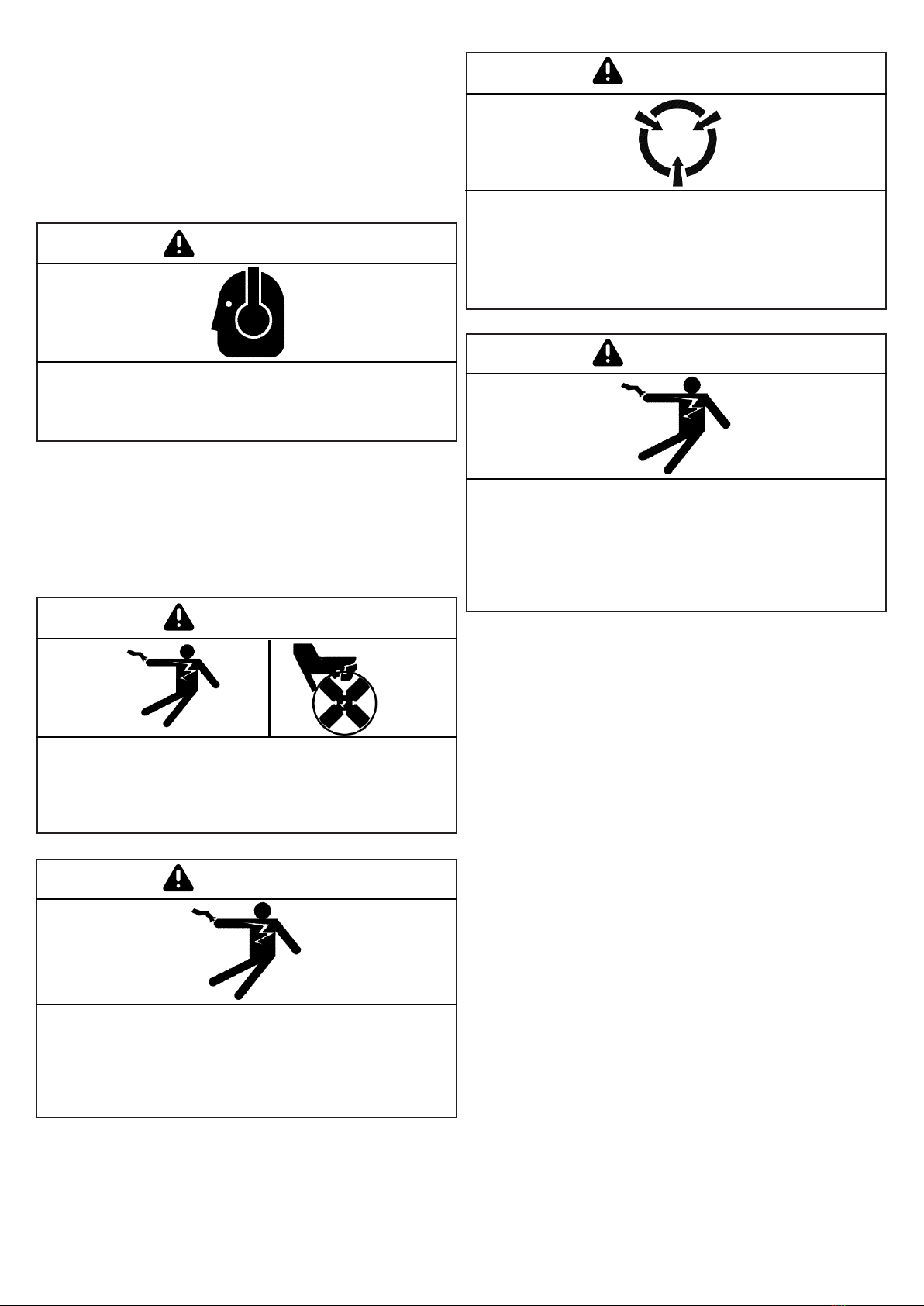
CAUTION
Hazardous noise. Can cause hearing loss.
Always wear ear production when engine room sound proofing
is incomplete
Engine noise. Hazardous noise can cause hearing loss.
Generator sets not equipped with sound enclosures can produce
noise levels greater than 105 dBA. Prolonged exposure to noise
levels greater than 85 dBA can cause permanent hearing loss.
Wear hearing protection when near an operating generator set.
Hazardous Voltage/Moving Parts
DANGER
Hazardous voltage. Moving parts. Will cause severe injury or
death.
Operate the generator set only when all guards and electrical
enclosures are in place.
WARNING
Hazardous voltage. Backfeed to the utility system can cause
property damage, severe injury, or death.
If the generator set is used for standby power, install
an automatic transfer switch to prevent inadvertent
interconnection of standby and normal sources of supply.
CAUTION
Welding the generator set. Can cause severe electrical
equipment damage.
Never weld components of the generator set without first
disconnecting the battery, controller wiring harness, and
engine electronic control module (ECM).
WARNING
Short circuits. Hazardous voltage/current will cause severe
injury or death.
Short circuits can cause bodily injury and/or equipment
damage. Do not contact electrical connections with tools or
jewellery while making adjustments or repairs. Remove all
jewellery before servicing the equipment.
Grounding electrical equipment. Hazardous voltage will cause
severe injury or death. Electrocution is possible whenever
electricity is present. Ensure you comply with all applicable
codes and standards. Electrically ground the equipment,
transfer switch, and related equipment and electrical circuits.
Turn off the main circuit breakers of all power sources before
servicing the equipment. Never contact electrical leads or
appliances when standing in water or on wet ground because
these conditions increase the risk of electrocution.
Connecting the battery and the battery charger. Hazardous
voltage will cause severe injury or death. Reconnect the
battery correctly, positive to positive and negative to negative,
to avoid electrical shock and damage to the battery charger and
battery(ies). Have a qualified electrician install the battery(ies).
Servicing the generator set when it is operating. Exposed
moving parts will cause severe injury or death. Keep hands,
feet, hair, clothing, and test leads away from the belts and
pulleys when the generator set is running. Replace guards,
screens, and covers before operating the generator set.
4
Heavy Equipment
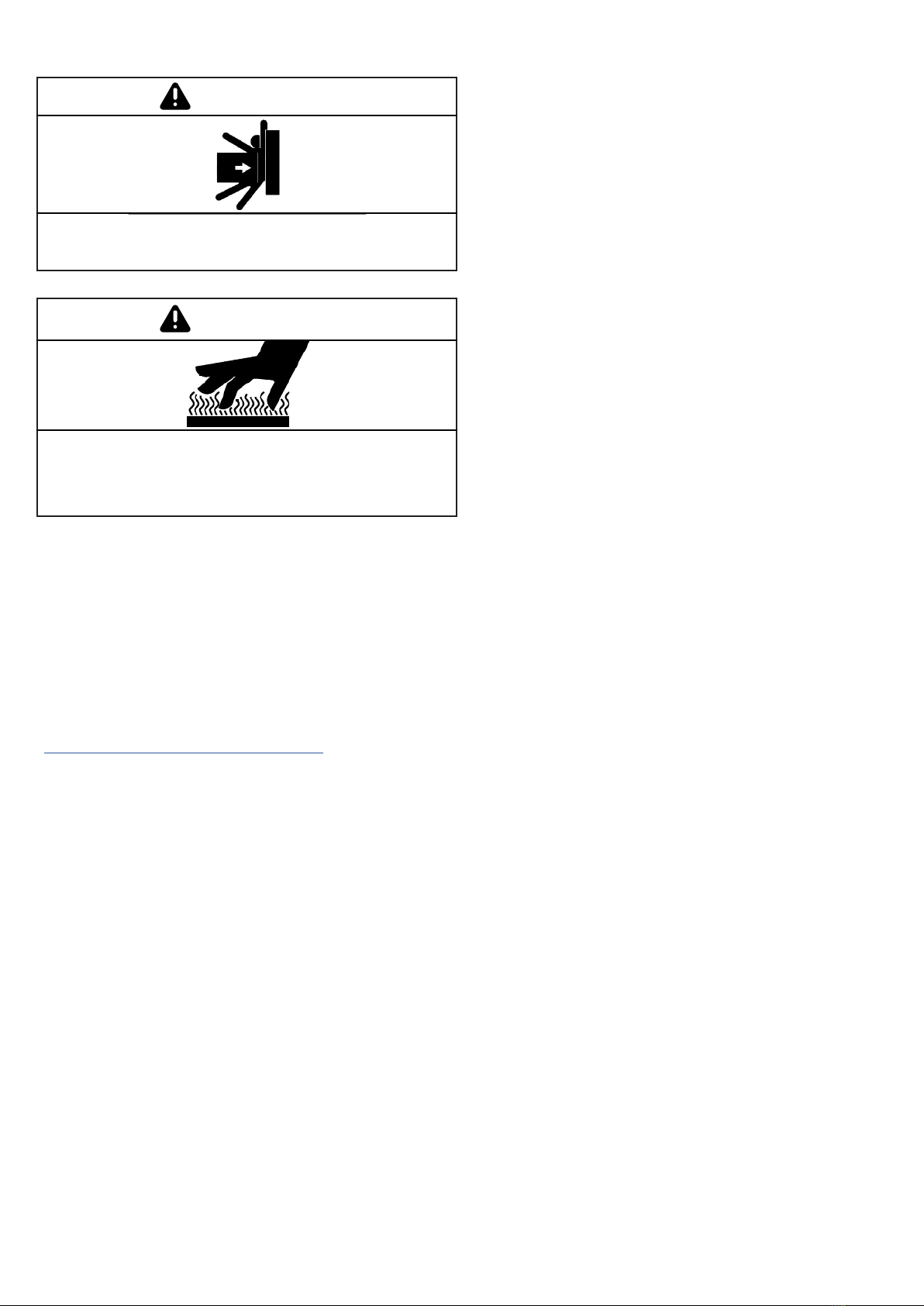
WARNING
Unbalanced weight. Improper lifting can cause severe injury
or death and equipment damage.
WARNING
Hot engine and exhaust system. Can cause severe injury or
death.
Do not work on the engine set until it cools.
Servicing the alternator. Hot parts can cause severe injury or
death. Avoid touching the alternator field or exciter armature.
When shorted, the alternator field and exciter armature become
hot enough to cause severe burns.
Hot parts can cause severe injury or death. Do not touch hot
engine parts. The engine and exhaust system components
become extremely hot during operation.
Refer to the Health and Safety Executive’s publications found at
http://www.hse.gov.uk/pubns/indg139.pdf
Fire and Ignition Protection
Where applicable, always follow the appropriate installation
standards regarding ignition protection. Electrocution is
possible whenever electricity is present. Ensure you comply
with all applicable codes and standards.
**Please locate any fire suppression sensors away from any
high power alternators and generators. These devices can
generate sufficient heat to trigger the suppression systems if in
close proximity**
5
Introduction
Integrel is a modern, intelligent way of generating, storing and distributing electrical energy
in off-grid applications, such as recreational marine craft, without fitting a standalone
generator with a second engine. It is completely automatic, delivering significant amounts
of energy seamlessly throughout the vessel without user input. It is fuel-efficient, reducing
overall fuel consumption for propulsion and generation, and very cost-effective with virtually
no maintenance costs. Integrel completely replaces a conventional generator and delivers
all of the power that you need to make living on board as comfortable as living at home.
For the boat builder, the Integrel system simplifies the electrical energy system substantially.
It is a complete power generation, storage, conversion and distribution system, providing
all of the vessel’s energy needs in one consolidated package. The Integrel system also
provides additional safety, engine and battery management tools for the end user for
handling today’s modern lithium-ion battery banks. The system will automatically alert the
user when the batteries need to be re-charged.
Simple busbar connections are provided for all AC and DC voltages and no changes are
required to the vessel’s downstream electrical systems.

Contents
1. Overall System Configuration and Components 8
2. Tools Required 10
3. Pre-fit Boat Survey 10
4. System Schematic 11
5. Installing and Connecting the Batteries 12
a. Lithium-ion 12
b. Lead-acid 12
6. Battery Bank Sensors 13
7. 48V DC System 13
8. Controller 14
9. Inverter 16
10. DC-DC Converter 16
11. Screen Interface 16
12. Comms, Cabling and Junction Box 17
13. Final Connections and Commissioning 18
14. Appendices 20
• 9kW engine mounted generator - the source of
Integrel’s electrical power.
• Engine mounting kit - specifically designed for the
vessel’s propulsion engine.
• System controller - the black box which monitors and
controls all of the system components.
• Battery sensor(s) (lead-acid or lithium-ion) - to
monitor the vessel’s battery systems, track state of
charge and set desired charging voltage.
Integrel controller
Integrel generator
AC distribution panel
48v negative busbar
Screen
48v battery data
Shore supply
48v positive busbar
Input from renewables
10mm
4 mm
4mm
70mm
70 mm
70mm
Gear detect
12v negative busbar
xxA
30A
Integrel system boundary
48
12
5A breaker
4mm
20A breaker
400A
MRBF
midi
30A
midi
30A
midi
ANL/class T
20A o/p
positive busbar
To existing 12/24v
Engine start battery
Permanently live 12v busbar
4mm
48
12
5A breaker
30A
midi
20A o/p
Data cable to sensors on:
House bank
200Ah200Ah
48v storage bank
200Ah200Ah
48v storage bank
Victron 24v200Ah Li ion batteries
400A
ANL/class T
B A
Li ion safety switch
200A breaker
Power conversion
Energy storage
3/5/8kVA 110/220v
Inverter/charger
Generation and control
J1939
400A
ANL/class T
200Ah200Ah
48v storage bank
Major 48v loads
winches/windlasses/thrusters
xxA
midi
70 mm
8
1. OVERALL SYSTEM CONFIGURATION AND COMPONENTS
The core components of the Integrel system and their functions are as follows:

• Integrel battery safety switch - a smart switch that
will disconnect automatically in any safety critical
event.
• 48v to 12/24v DC-DC converter - various options
available.
• 5” touch screen user interface - displays live
information of the Integrel system.
• Screen interface box - converts our own CAN data
into a format compatible with the screen.
• Communications junction box - the point where all
of our network cables can meet.
• Switch panel - Also included is a switched breaker
panel for the Integrel controller and DC-DC converter
Additional third party components which complete
the Integrel system are:
• Batteries for energy storage, either lead-acid or
lithium-ion, configured for 48V DC.
• Inverter/charger to convert electrical energy stored
at 48V DC to 110/240V AC. It also allows you to charge
your batteries from shore power.
9
Skills Required
Installing an Integrel system is less complex and time consuming than installing a traditional generator, but still
requires experience and guidance from Triskel Marine. It is intended to be installed by a qualified installer, with
online access to Integrel’s system setup software and other Integrel resources.
As far as possible, everything is preconfigured, including wiring harnesses. Detailed videos are available on the
Integrel Marine YouTube page to illustrate the various stages.
(https://www.youtube.com/channel/UCyxkU5XIGfVQW4MSbnQ7WVw)

The Integrel system can mostly be installed with
commonelectricalhandtools. Mostmarineelectricians
will have:
• Insulated screwdrivers
• Insulated spanners
• Standard spanners (metric and imperial)
• Allen keys
• Socket set
• Ratcheting insulated terminal crimp tool
• Non insulated terminal crimp tool 10mm2-120mm2
(8AWG - 4/0AWG)
• Hot air gun
• Cordless drills for mounting parts
• Thermal imaging camera
• Independent 12V power source/battery
• Insulation strippers
You may not have a thermal imaging camera, however
we feel this is a crucial piece of equipment for checking
your work and ensuring there are no bad connections.
2. TOOLS REQUIRED
Prior to starting the installation, it is essential to carry
out a physical survey of the boat to identify where the
individual components will be fitted. This is particularly
important for the batteries which are likely to be the
largest and heaviest items. For specific sizes and weights,
please refer to our website. Batteries must be installed in
a dry space and well clear of any area where there might
be water ingress (see ISO 10133 for details). Ensure all
restraints and mounts are to a suitable standard.
Batteries
All batteries, but particularly lithium-ion, are sensitive
to temperature. It is essential that the batteries are
positioned in the coolest possible location in the boat
and there is plenty of air circulation around them.
lithium-ion batteries will automatically disconnect if their
internal temperature exceeds a given limit, which may be
as low as 45°c. If prolonged operation in high ambient
conditions is required, careful attention must be paid to
the manufacturers’ operating limits and battery choices
should be made accordingly. There may also be low
tempertature usage limits with some batteries.
Lead-acid battery spaces must be vented to the exterior.
If in doubt about the effect of the battery weight on boat
trim, consult a naval architect.
Cable Routes
Routes for cabling need to be identified as part of the
survey, bearing in mind that cable lengths should be
kept to a minimum to reduce cable losses. Details of
recommended cable sizes are given in Annex B. Most
vessels have conduits for major cable runs and these
should be used where possible.
Please note: the positive and negative power cables
should be run together to reduce stray magnetic fields.
These should always be kept clear of bilge areas. Data
cables, AC power cables and DC cables should be run
separately if possible.
Generator
The generator is mounted on the front end of the engine
and is normally driven from an additional pulley bolted
to the existing crank pulley. Depending on the make of
engine, the Integrel generator may extend outside the
normal envelope of the engine. Be sure to check that
there is sufficient room to accommodate any overhang.
Installation instructions are included with each specific
engine fitting kit.
Screen
The screen can be mounted remotely from the other
system components and should be positioned where
it is easy to see from the main saloon. The display has
been designed to show the battery state of charge and
voltage at a glance and it is useful to be able to see it
easily from all of the common spaces. The screen also
displays various alarms and alerts and must be accessible
in order to acknowledge and clear alerts. A template for
the screen cut-out is given in Annex C, or you can use the
supplied screen mounting panel.
Battery Switches
The main battery switches are solenoid operated and
are normally actuated automatically by the system itself.
They are also fitted with a mechanical actuator and need
to be accessible in case of an electrical failure. Ensure
you have a suitable location available for the switches.
Busbars
These are used as a primary means of connecting
common DC power cables. Ensure all connections are
booted and protected from short circuit.
Battery sensor
The battery sensor measures battery parameters such
as individual battery voltage and bank temperature. The
sensor then communicates with the controller, which
delivers the right amount of power to correctly charge
your battery banks as quickly and efficiently as possible.
3. PRE-FIT BOAT SURVEY

11
Loom
The main loom is supplied in two parts, the three main
phase cables are together in one part, and the second
part has smaller wires. These two looms connect the
controller to the generator, which allow the controller
to accurately control the generator output. The
loom with the three phase cables transports the AC
power from the generator to the controller where it is
rectified to 48V DC. The loom with the smaller cables
brings temperature inputs from the engine, generator
and ambient to further optimise generation. We also
use this loom to detect when gear is selected, which
allows propulsion to always be prioritised.
Inverter/Charger
We recommend fitting an inverter/charger suitable for
giving you all the AC power you need, which is how the
48V DC is converted into either 110V or 230V AC. The
charger element of the inverter is used to maintain
the 48V batteries when shore power is available. It
is advised that the inverter be placed as close as
practicable to the batteries, and that the cable be
upsized to prevent potential ripple under load.
DC-DC Converter
The DC-DC converter, gives a trickle charge from the
48V battery storage bank to the 12V/24V house banks.
This is often a setting that must be set to the house
bank float voltage, and is normally left on at all times.
This should be set to ‘float voltage’ for the house bank.
On/Off Switch
The Integrel switch should be left on at all times,
therefore it should be located in a position where it
cannot be knocked. The Integrel system uses a very
small amount of power in sleep mode but can draw up
to 15A whilst generating. The supplied switch panel
also has a switch for the DC-DC converters to allow
the owner to turn these off should the boat be left
without shore power.
Controller
The main controller should be sited in a dry location
within a 3m cable run of the generator. The system
needs reasonable airflow and under heavy load can
become hot, so please consider the location carefully.
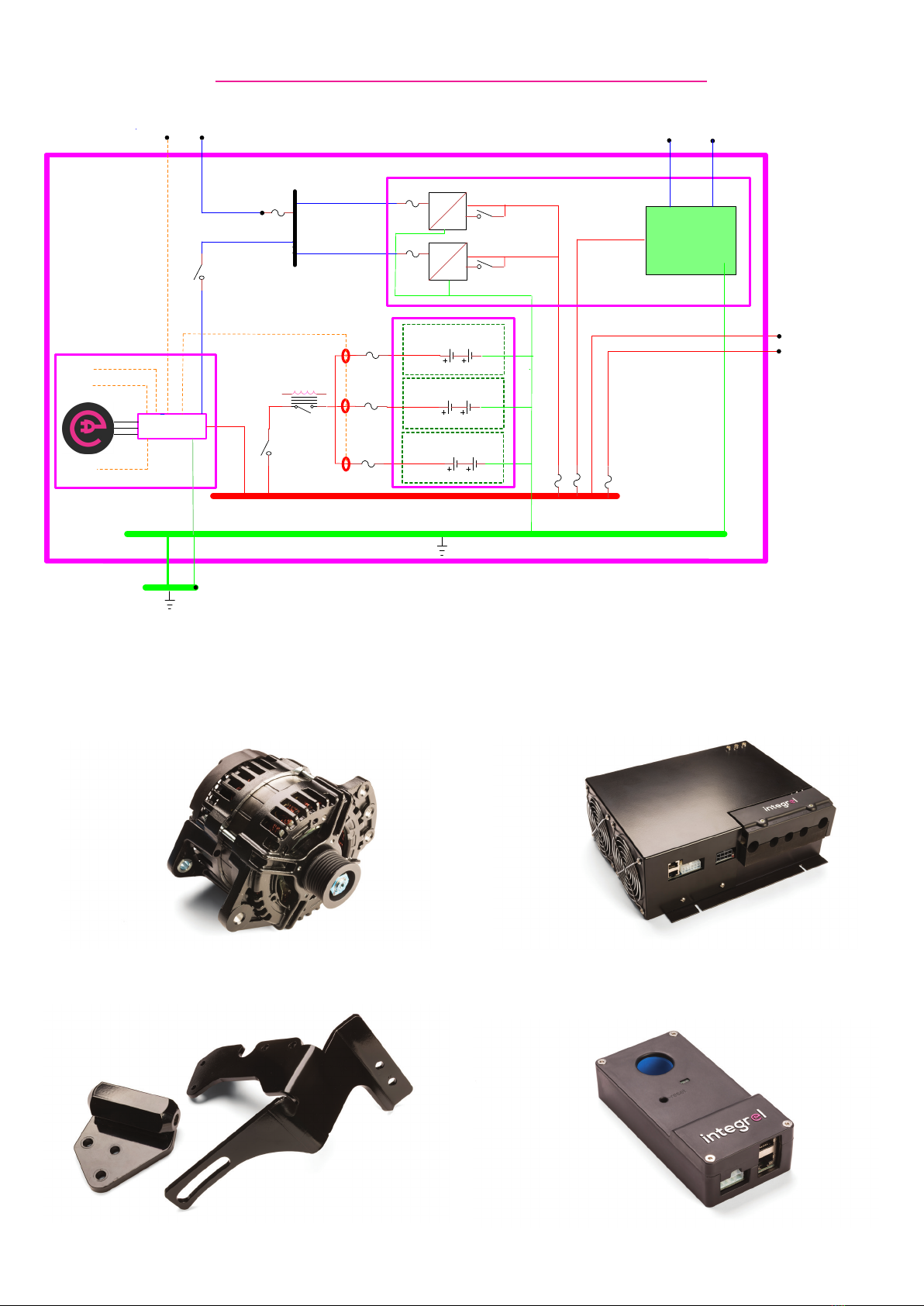
4. SYSTEM SCHEMATICS
A detailed schematic is provided for each particular
installation and should be followed closely. Each circuit
within the schematic has been designed in the light of
many years of experience and no changes should be
made without referring back to Triskel Marine.
A few basic principles are illustrated in the attached
schematics:
• Each battery bank is individually connected to the
48V power busbars (positive and negative) and must
not be paralleled together in any other way. Each of the
banks is fitted with a battery sensor which monitors
battery state of charge and determines the charging
voltage. If the batteries are not individually connected
to the busbar, the state of charge calculation will be
wrong.
• We normally fit a permanently live 12V busbar
supported by a DC-DC converter from the main energy
storage batteries and by the 12V house battery bank.
This allows the Integrel controller to be left energised
when the rest of the boat is powered down, in order to
keep track of the battery state of charge. If the system
is fully powered down, state of charge will be reset on
the next occasion that the batteries are charged to
100%.
• Cable and fuse sizing in the schematics is based on
ISO 10133 and ABYC E-11. Guidance is provided in
annex B.
• Overall management of the system is provided by
the controller which receives information from all of
the system components via a closed data network.
Data cables are fitted to each device and may be daisy-
chained together, connected in a star configuration or
a combination of the two.
• You may require multiple battery sensors, please
ensure you have the required number of sensors and
cables.

12
5. INSTALLING AND CONNECTING THE BATTERIES
The Integrel system works equally well with both lead-
acid and lithium-ion batteries. The type and number of
batteries will have been determined during the system
design phase and the choice is influenced by a number
of factors:
• Typical 24 hour AC and DC power consumption
• Maximum loads seen on all circuit types
• Desired period of autonomy (“silent operation”)
• Typical 24 hour operational profile
Battery Choice and Installation
5.1 We currently support the following battery
manufacturers: Torqeedo, Victron, Relion and
Mastervolt. These weigh in excess of 25kg each, so
consideration must be taken as to where they are
sited, supported and secured.
5.1.1 It is important to note that battery
age, chemistry, brand and capacity must
not be mixed. This applies not only to the
batteries within each bank but also across
all banks. If you chose to add another
bank of batteries at a later stage, these should
be monitored for a full charge and discharge
cycle. If any discrepancy is seen between new
and old banks, all old banks must be replaced.
5.2 When unpacking lead-acid batteries, be sure to
check the voltages. They should all be above 12.8V
and should have a difference of no more than 0.2V
between batteries.
5.3 With lithium-ion batteries, it is common practice
to ship these at or below 50% state of charge (SOC).
In contrast to lead-acid batteries, lithium-ion batteries
do not like being left at 100% SOC. These batteries will
not balance individual battery voltage if they are not
properly synchronized before linking together in series.
For this reason, it is common practice to charge each
battery to a certain voltage stipulated by the battery
manufacturer before connecting batteries together
in series. Please refer to the battery manufacturer’s
installation instructions for details on this procedure.
**This procedure is vital for a system to work
effectively and for the useable capacity to be
maximised. Please refer to the battery manufacturer
documentation for more information**
5.4 Once you have confirmed the batteries are in good
condition and correctly charged, a suitable location
should be found where the batteries can be mounted
and secured properly. The best solution is to mount
the batteries close to each other with a suitable air
gap between blocks. Batteries should be packed
and secured so they will not move should the boat
encounter rough seas. If it is not possible to mount
batteries in one area, cable lengths between batteries
should be kept as short as possible and all link cables
should be made of at least 70mm2 tinned marine
cable. It is important to try and keep all batteries
in the system at a similar ambient temperature, as
differences between batteries or battery banks can
cause imbalances between them.
5.5 Link bars or cables should be fitted and torqued to
the battery manufacturer’s specifications.
5.6 A high interrupt current fuse (such as a Class T
or ANL fuse) should be fitted as close as practically
possible to the positive battery terminal, this will
protect the battery from a short circuit and should be
rated at well above the maximum expected load. A
breaker should also be fitted to protect the cable from
overcurrent. This should be fitted as stipulated in the
schematic for the individual installation.
5.7 In some cases, a battery terminal stud may be
supplied, which allows the battery bank sensor to
be fitted right next to the battery bank. If a terminal
stud is not supplied, or will not fit for the particular
installation, it is recommended that the battery sensor
is fitted over one of the battery cables (it may be
necessary to fit the sensor before crimping the final
terminal on to allow the sensor to pass over the cable
end). The chosen cable must take the entire bank
current - this could be a positive or a negative cable,
but not an intermediate link cable.
***Do not connect any battery bank until ALL other
48V wiring is complete***
**Always follow battery manufacturers installation
and application instructions**
5.8 The Integrel safety switch should be fitted as
close to the battery bank as possible, with no other
connections between it and the battery other than
the primary fuse (all load and charge sources need to
be on the switched side of the safety switch, not the
battery side). When a battery bank reaches a critical
low voltage or high temperature it will automatically
disconnect the bank to prevent damage to the battery.
The positive cable connects to the 48V positive
battery terminal, and the negative cable connects to
the negative terminal. If connected to the Integrel
data bus, it can also monitor and report other fault
conditions on the bus. Some battery types require
specific interfacing between the battery BMS and the
safety switch to allow disconnect and control directly
from the battery. This may require an optional wiring
loom as it is battery and model specific. Please contact
Integrel for more information as required, this should
be considered as part of the initial specification and
schematic process.
The main battery cables connect directly to the main
terminals. This should be done with the switch in the
off position, by pulling up on the knob. This knob
allows manual activation of the switch should it be
required.

13
6. BATTERY BANK SENSORS
7. 48V DC SYSTEM
7.1 Find a suitable place for the battery solenoid switch,
this should be on the positive battery cable as close to
the battery bank as is practical. Fix the battery switch
in place with appropriate fastenings. Further details
will be provided with the switch.
***Ensure that battery switch is in the off position***
***Do not connect at this time***
7.2 Find a suitable place for the positive and negative
busbars. Use different locations for each busbar. It
should not be possible to short with a spanner between
the two busbars whilst working on them.
7.3 Select the appropriate size cables for connecting
the battery bank with the busbar for the maximum
possible load. These will be detailed in the system
schematic. As mentioned previously, a high interrupt
capacity fuse AND an appropriately sized circuit
breaker should be fitted before the battery switch.
The fuse will protect the battery and the breaker will
protect the cabling.
***Always size cable appropriately***
7.4 Connect the 48V negative busbar to the boat’s
common grounding point with a suitably sized cable
(no less than 35mm2). If not already linked, also fit a
negative link between any 12V and 24V battery banks.
7.5 Run cables between the busbar and the battery
bank(s), but do not connect.
Important:
• Always ensure the 48V system is isolated before working on it.
• Ensure a fuse/breaker is appropriately sized and sited (on the positive side) for every
reduction in cable cross-sectional area where the cable is in use.
• Label all cables at both ends.
6.1 Place the battery bank sensor over the sensor post
or battery bank cable.
6.2 The bank sensor loom will have between 3 and 6
cable ends depending on your chosen batteries and
the voltage of the bank. please refer to Annex D. The
twin core black cable with the non insulated terminal
on the end is the temperature tap. The black wire is 0V.
The remaining four red cables are voltage tap 1, 2, 3
and 4. If using a loom for the PC1800 batteries with the
copper busbars, tap 1 is the shortest and tap 4 the
longest. If using the non-specific battery loom, the
terminals will be labelled.
6.3 If using 4 x 12V batteries, use tap 1 for 12V
(from 0V tap), tap 2 for 24V, tap 3 for 36V and
tap 4 for 48V.
If using 24V batteries use tap 1 for 24V and tap
2 for 48V. If using a single 48V battery use tap 1 for
48V.
6.4 Fit the 0V tap at the point where the negative cable
leaves the battery bank.
6.5 Fit the positive voltage taps as shown in Annex D.
6.6 Re-fit and tighten all terminal fastenings and
torque to manufacturer’s specification.
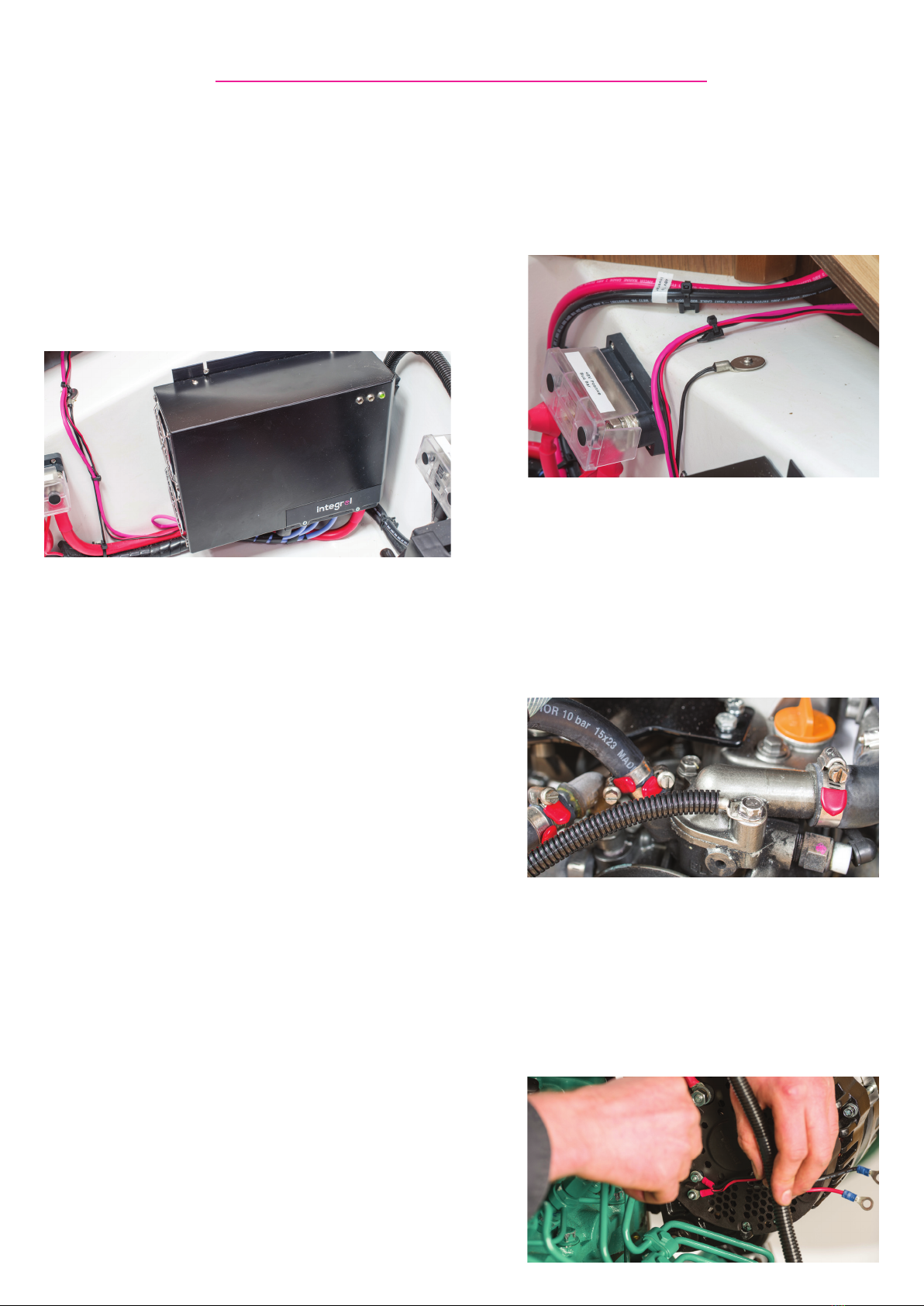
8. CONTROLLER
8.1 The positioning of the controller is important.
It should be within a 3m cable run of the Integrel
Generator (cable loom is supplied at 2.9m), and should
also be located in a clean and dry environment. The
controller is designed to be bulkhead mounted with
the fans on the left, however it may be mounted in
either orientation. If bulkhead mounting in the portrait
orientation the fans must be at the bottom. The
controller can also be mounted on a horizontal surface
providing it is properly secured.
8.2 Once the correct location has been determined, the
controller should be mounted with four appropriate
screws, once the holes are marked. It is best to screw
the lower two screws in most of the way and slide
the controller onto these, before adding the last two
screws and tightening all four.
8.3 Connect the Integrel generator to the controller
with the two pre-made looms supplied. The first loom
has two Molex plugs (one black, one white) and is for
the data input, power to the controller and power
to the generator. The plugs should be fitted to their
appropriate holes on the controller.
8.3.1 You will notice there are a pair of cables
attached to the black plug that are separate to
the rest of the loom. These are the main 12V
power cables to power the system and
should see no more than 20A. The positive
should be attached to a breaker for the system
and the negative to the boat’s negative.
8.3.2 Working your way away from the
controller, the first connection you will see is
the two-way Molex plug for the gear detect
switch. This plug should remain connected if
you plan on using a neutral switch from the
gearbox, or if you plan on extending these
cables from the engine side of the loom to
the throttle control neutral switch. If you plan
on using a neutral switch nearer the Integrel
controller, you should separate this plug and
use the adaptor loom provided. It may be
necessary to extend this to reach the throttle
control. See Annex E.
8.3.3 Continue working away from the
controller, the next terminal you will find is
the ambient temperature tap. This will be
around 0.5m from the controller. It is a 10mm
ring terminal connected with a twin core
cable. Secure this to a bulkhead in the same
space as the controller.
8.3.4 The next twin core cable with a single
ring terminal at the end is the engine
temperature tap. This will be located at the
engine end of the loom and should be
positioned at the hottest point of the engine’s
fresh water cooling circuit, ideally the
thermostat housing. Ensure this cabling is
properly protected and secured to avoid any
damage from engine vibrations.
8.3.5 At this point you will be left with four
ring terminals, a pair of bare ends, and a 4-pin
plug on this loom. You will notice that there
will be two pairs of ring terminals, a pair of
4mm and a pair of 5mm ring terminals. The
4mm terminals are the thermistor
connections. These are to be fitted to the two
4mm studs on the back of the generator.
15
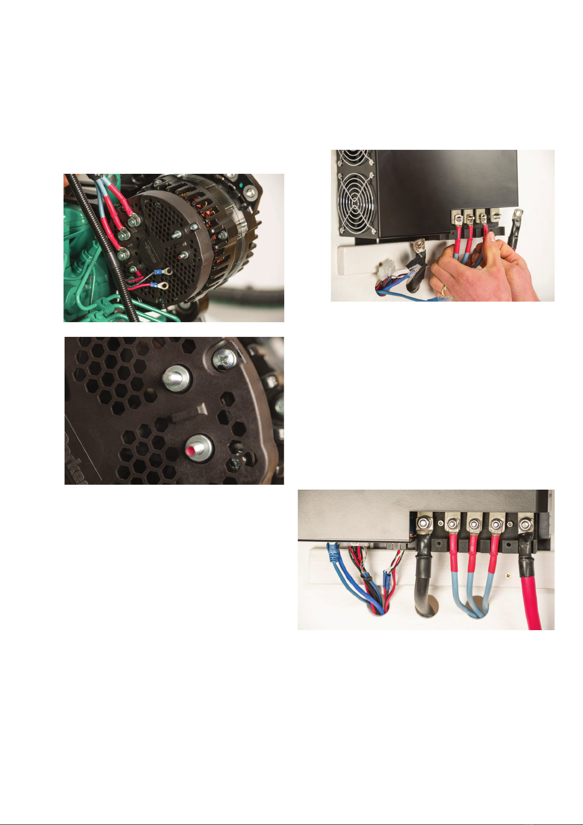
8.3.6 The larger pair of ring terminals are the
field connections. Careful attention should be
paid to the polarity of these terminals. The
red cable should go on the F+ terminal. The
black cable should go on the F- terminal. (If
these are fitted incorrectly, the max output
will not exceed 1.5kW, but no damage will be
done).
8.3.7 The remaining 4-pin plug is an optional
plug to be used if the engine has an ECU. An
adapter cable will be supplied if the engine is
capable of this function.
8.3.8 Remaining bare-ended cables are for
the neutral detect switch, as mentioned
previously (see Annex E). You may have a
neutral detect switch available on the gearbox.
If you plan on using this, then you should
ensure the in-line plug is connected at the
controller end. If you have disconnected the
plug at the controller end, this cable is
redundant. If the throttle control is already
connected to the engine loom, it may be
possible to pick up the gear detect via
the engine CAN BUS network, in this case the
engine ECU adapter must be used. These
ECU cables are engine specific and
various options are available. Please contact
Integrel for advice, and this should be
considered during the specification process.
8.4 The second loom houses the three phase
cables. These transport the unrectified power from
the generator to the controller where the power is
rectified. It is not important which phase cable goes
to which stud on the generator or the controller.
8.4.1 At the controller end, first remove the
plastic terminal cover, then connect the three
phase cables to the three M6 studs on the
controller.
8.4.2 Then connect the other with the 8mm
studs to three phase studs on the generator.
8.5 Run in and connect the positive and negative
cables between the respective busbars and the
positive and negative studs on the controller. Ensure
correct connection!

16
9. INVERTER
9.1 Find a clean, dry place away from sensitive electronics
and securely mount the inverter in accordance with the
manufacturer’s specifications.
*** Inverters have large capacitors. Once connected
to 48V, they will be charged - bear this in mind when
working on the 48V system. There may be significant
residual energy stored in the inverter even after it has
been turned off**
9.2 Run in and connect the positive and negative cables
to their respective busbars. These should be fused
according to cable sizing all noted on the installation
schematic. Always keep the inverter location as close as
possible to the batteries.
*** Ensure all 240V/110V power is disconnected from the
boat, including other inverters***
9.3 Connect the AC power as described in the inverters
manual.
9.3.1 Depending on the boat setup, it may
be necessary to use different feeds to that of
a standard inverter. Some boats have two AC
circuits, one powered only by shore power
and one that can be powered by an inverter.
If you have sized the inverter appropriately,
you can connect into the shore power circuit.
This means you will be able to supply all
appliances on your boat, including the high
power consumers such as water heaters,
microwaves and cookers.
9.4 Switch the inverter on and configure the charging
profiles correctly for the battery make and model you
have. This is essential for lithium-ion batteries.
10. DC-DC CONVERTER
10.1 Find a suitable location that is clean and dry.
Mount the DC-DC converter with suitable fastenings.
10.2 Run in and connect a suitably sized positive cable
from the 48V busbar through a suitably sized circuit
breaker or fuse to the 48V positive terminal on the DC-
DC converter via the supplied switch.
10.3 Run in and connect the same sized negative cable
directly from the 48V negative busbar to the DC-DC
converter.
10.4 Run in and connect the positive and negative
cables directly to the 12/24V house ban. These cables
should be suitably sized and fused. Note that there
will be more current flowing on the 12V/24V side.
10.5 Refer to DC-DC converter installation instructions
for remote switching. With some models it may be
possible to switch the DC-DC converter without
passing all input current through a switch.
***Ensure negative cables are both connected and
commoned. A smaller busbar is useful for this***
11. SCREEN INTERFACE
11.1 Find a suitable place to mount the display screen
where it is possible to flush mount and have access to
run the cabling. It should be easy to read and reach,
and secured with appropriate fixings.
11.2 Fit the screen interface box within 200mm of the
screen, this should be semi accessible as this is the
point at which the system software can be updated via
the USB port.
11.3 Connect the screen loom between the screen
interface box white 12-way Molex plug and the two
deutsch plugs on the back of the screen. Though
the plugs have the same number of pins, they have a
different register and will only fit in the correct socket.
11.4 The supplied alarm buzzer should be connected
to the four-pin connector and mounted appropriately.
11.5 Given the screen is a relatively high
user of power, it is important that the Screen
interface box is plugged directly into one of
the ports on the controller as this is the only
power source on the Integrel CAN bus system.

17
12. COMMS CABLING AND JUNCTION BOX
12.1 Find a clean dry place for the junction box as close
to the centre of the kit as possible and secure with
appropriate fastenings.
12.2 Run cables from the junction box to:
12.2.1 Battery safety switch
12.2.2 Battery sensor(s)
12.2.3 Controller
12.3 Many of the components have the facility to
“daisy chain” the data cables. This is possible if
components are close by, but depending on the
system layout it may be better to bring all cables to
the junction box where possible.
12.4 We operate a CAN bus system. For this to work
properly, we need two terminating resistors connected
to the data bus. The junction box and the screen
interface box both have resistors built into the circuit
board.
12.5 If a second junction box or second screen
interface box is to be used, you will need to make sure
you don’t have more than two terminating resistors in
the system. This can be done by removing the correct
number of “jumpers”. To do this, first remove the lid
and, with tweezers or long nosed pliers, remove the
“jumper” from the position marked R120, as shown in
the images below.

18
13. FINAL CONNECTIONS AND COMMISSIONING
13.1 Check all 48V connections for correct connection
and tightness.
13.2 With the battery switches locked off (turn the knob
90 degrees to the ‘off’ position – this feature is only
intended for use during installation), connect all 48V
battery banks. Be sure to include the tap cables for the
bank sensor and battery safety switch at this time.
13.3 Turn the Integrel system on at the Integrel switch
panel.
13.4 IMPORTANT! At this point the system will require
configuration using the Integrel setup application. Please
see annex F for details on this.
13.5 If there are any issues with the installation, there will
be a beep from the display screen and an error displayed.
Common installation errors are incorrect or missing
voltage or temperature sensors, or other cabling issues.
The screen errors will pinpoint as closely as possible the
source of the fault, which should be rectified in order.
A ‘Low system voltage’ is an acceptable error, as this
message means that all sensors are functioning correctly,
but the main battery switches are open. This message
should clear when you reach stage 13.7.
13.6 It is important to set the zero reference of the
sensors. Plug in the configuration loom (supplied to
installers on request, not a standard item), and connect
to an independent 12V power source that is not being
monitored by the sensors.
**It is possible to set the zero point and current polarity
through the setup app, please see Annex F. The
following instructions are to set up sensors directly
during installation. Either method is acceptable**
13.6.1 With all battery switches off (including
any form of charging) and the DC-DC
converter(s) off, go to each battery sensor
and insert an object such as a 3mm allen key
into the “reset” hole. Press and hold the zero
button until the blue light comes on. It is
important to release as soon as the light
changes to blue.
13.7 One at a time, switch the battery banks on. If you
locked the safety switch out (see point 13.2) during
installation, return the knob to the correct position before
you do this.
13.8 Look at each battery bank current readings on
the display screen. For each bank in turn, apply a load
or charge to ensure the polarity is correct. If you are
discharging, the power figure should read negative kW.
If you are charging, power displayed should be a positive
figure.
13.8.1 If the current flow on the sensors is
incorrect, press the “reset” button again. This
time, hold the button past the point at which
the blue light comes on and release when the
blue light goes off again. This will change the
polarity. Now repeat step 13.6.1 to properly
set the zero on that bank.
13.9 Remove the configuration loom and separate the
12V source and return to the boat’s power for the system.
13.9.1 Switch the DC-DC converters on at the
Integrel panel.
13.10 Start the engine. If a connection to the engine ECU
had been made, the generator will not begin generating
until the engine coolant reaches 30oC. After this point,
the generator will begin to work. The generator page will
show an output in kW.
13.11 Charge the 48V batteries on shore power for 24
hours. This will ensure the state of charge figures are
correctly setup.
13.12 Unplug the boat from shore power.
13.12.1 With the electrical system under load,
(use electrical appliances to draw lots of
power off the batteries), allow the battery
state of charge to drop to around 80%.
13.12.2 With the electrical loads still on, start
the engine and run at 1/3 to 1/2 throttle. The
output should peak between 8kW and 9kW.
This will then drop to between 6kW and 8kW
as the generator will be limited on
temperature.
13.12.3 Check all 48V connections with a
thermal imaging camera. Ensure the system
has been running for several minutes under load
before concluding this check. Any connections
with high temperatures should be
disassembled and checked once the system
has been turned off, all batteries isolated and
the connection has been allowed to cool.

19
***Do not check terminal connection by
touch, they may cause burns.***
13.12.4 Once you have checked all terminals,
turn off all non-essential appliances and allow
the system to complete a charge cycle. This
may take an hour or more if you are using a
large battery bank. It is important that you
observe the system tripping to the float
voltage stated on the battery page.
Post-Installation Checklist
Engine
• All nuts and bolts are correctly fitted and torqued to
specification.
• The belt is fitted correctly.
• Engine test run and belt alignment checked.
Electrical System
Here are a few points to check through once the
installation has been completed:
• Batteries correctly installed, supported and secured.
• Battery connections torqued to specification.
• All electrical connections checked with a thermal
imaging camera whilst under load.
• All battery sensors read correct direction of current
flow.
• With batteries discharged and engine running at 2/3
throttle, maximum output was ______kW.
• With the system charging hard, the generator
temperature stabilised and engine running at 1/3
throttle in neutral, the sustained output was _____kW.
• With the system charging at idle in neutral, selecting
gear brings the generator output to zero.
When charging hard, individual battery voltages were:
• All 48V battery banks have been on shore-power
charge for at least 24 hours.
• Owner has been briefed about the workings of the
system, what to expect in terms of output with their
particular type of batteries and the limitations of the
system.
Firmware and Software Updates
It is possible to simply update the entire system should
any future development or improvements need to be
made.
The update file can emailed or downloaded from the
Integrel system website. This file should be copied to
a USB memory stick without changing the filename.
With the Integrel system powered up, insert the
memory stick into the USB connector located between
the data cables on the screen interface box. After a few
seconds, the display will change to ‘installing update’.
**Do not power down the system at this point**
Once the update has loaded, the display screen will
reboot. Any devices or sensors on the system that
also need an update will be detected, and the screen
will ask for confirmation before updating each in turn.
Once the updates are complete, the screen will revert
to the standard display, and the system is ready to use.
At this point, it is safe to remove the USB drive from
the system.
Bank 1 – Block 1_____V Block 2_____V Block 3_____V Block 4_____V
Bank 2 – Block 1_____V Block 2_____V Block 3_____V Block 4_____V
Bank 3 – Block 1_____V Block 2_____V Block 3_____V Block 4_____V
Bank 4 – Block 1_____V Block 2_____V Block 3_____V Block 4_____V

20
APPENDICES
Annex A
Integrel controller
Integrel generator
AC distribution panel
48v negative busbar
Screen
48v battery data
Shore supply
48v positive busbar
Input from renewables
10mm
4 mm
4mm
70mm
70 mm
70mm
Gear detect
12v negative busbar
xxA
30A
Integrel system boundary
48
12
5A breaker
4mm
20A breaker
400A
MRBF
midi
30A
midi
30A
midi
ANL/class T
20A o/p
positive busbar
To existing 12/24v
Engine start battery
Permanently live 12v busbar
4mm
48
12
5A breaker
30A
midi
20A o/p
Data cable to sensors on:
House bank
200Ah200Ah
48v storage bank
200Ah200Ah
48v storage bank
Victron 24v200Ah Li ion batteries
400A
ANL/class T
B A
Li ion safety switch
200A breaker
Power conversion
Energy storage
3/5/8kVA 110/220v
Inverter/charger
Generation and control
J1939
400A
ANL/class T
200Ah200Ah
48v storage bank
Major 48v loads
winches/windlasses/thrusters
xxA
midi
70 mm
Table of contents
Popular Inverter manuals by other brands

Sunshare Solar
Sunshare Solar Solar LED Batten Light user manual

Bolanmu Energy
Bolanmu Energy xth 3000-12 ASSEMBLY QUICK GUIDE

Sungrow
Sungrow SC50HV user manual

RBI
RBI UL 2703 installation guide

Siemens
Siemens SINAMICS V20 Inverter operating instructions

Xantrex
Xantrex Trace Series installation instructions


