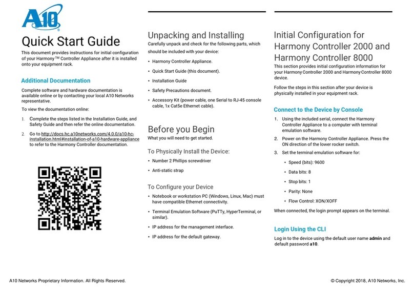
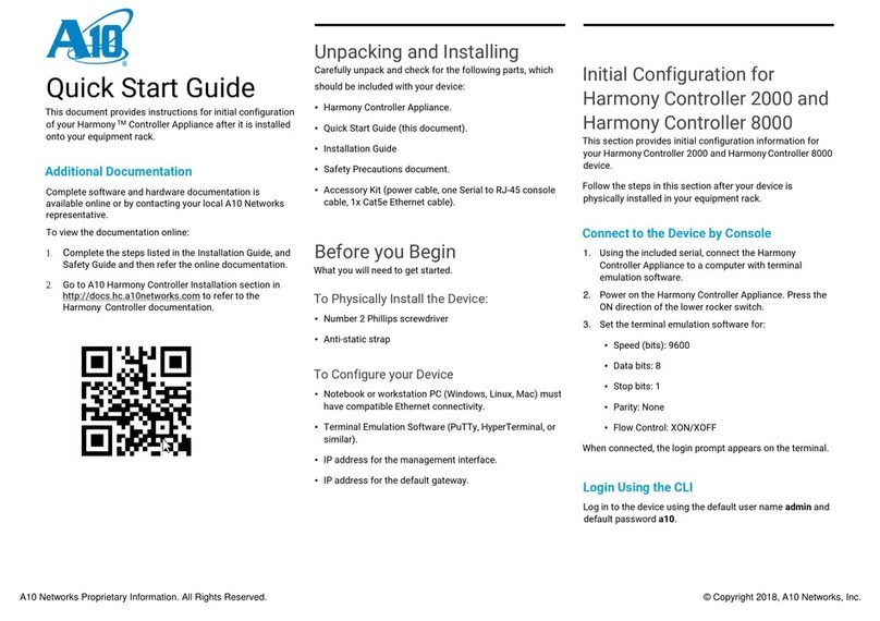
A10 Harmony Controller 2000 User manual

1 | P a g e A 1 0 H a r m o n y TM C o n t r o l l e r 2 0 0 0 I n s t a l l a t i o n G u i d e

2 | P a g e A 1 0 H a r m o n y TM C o n t r o l l e r 2 0 0 0 I n s t a l l a t i o n G u i d e
© 2018 A10 Networks, Inc. Confidential and Proprietary - All Rights Reserved
Information in this document is subject to change without notice.
Patent Protection
A10 Networks products are protected by patents in the U.S. and elsewhere. The following website is provided to
satisfy the virtual patent marking provisions of various jurisdictions including the virtual patent marking provisions of
the America Invents Act. A10 Networks' products, including all Thunder Series products, are protected by one or
more of U.S. patents and patents pending listed at:
https://www.a10networks.com/company/legal-notices/a10-virtual-patent-marking.
Trademarks
The A10 logo, A10 Harmony, A10 Lightning, A10 Networks, A10 Thunder, aCloud, ACOS, Affinity, aFleX, aFlow,
aGalaxy, aGAPI, aVCS, AX, aXAPI, IDsentrie, IP-to-ID, SSL Insight, SSLi, Thunder, Thunder TPS, UASG, and vThunder
are trademarks or registered trademarks of A10 Networks, Inc. in the United States and other countries. All other
trademarks are property of their respective owners.
Confidentiality
This document contains confidential materials proprietary to A10 Networks, Inc. This document and information and
ideas herein may not be disclosed, copied, reproduced or distributed to anyone outside A10 Networks, Inc. without
prior written consent of A10 Networks, Inc.
A10 Networks Inc. Software License and End User Agreement
Software for all A10 Networks products contains trade secrets of A10 Networks and its subsidiaries and Customer
agrees to treat Software as confidential information.
Anyone who uses the Software does so only in compliance with the terms of the End User License Agreement
(EULA), provided later in this document or available separately. Customer shall not:
1. reverse engineer, reverse compile, reverse de-assemble or otherwise translate the Software by any means
2. sublicense, rent or lease the Software.
Disclaimer
This document does not create any express or implied warranty about A10 Networks or about its products or
services, including but not limited to fitness for a particular use and non-infringement. A10 Networks has made
reasonable efforts to verify that the information contained herein is accurate, but A10 Networks assumes no
responsibility for its use. All information is provided "as-is." The product specifications and features described in this
publication are based on the latest information available; however, specifications are subject to change without
notice, and certain features may not be available upon initial product release. Contact A10 Networks for current
information regarding its products or services. A10 Networks’ products and services are subject to A10 Networks’
standard terms and conditions.
Environmental Considerations
Some electronic components may possibly contain dangerous substances. For information on specific component
types, please contact the manufacturer of that component. Always consult local authorities for regulations regarding
proper disposal of electronic components in your area.
Further Information
For additional information about A10 products, terms and conditions of delivery, and pricing, contact your nearest
A10 Networks location, which can be found by visiting www.a10networks.com.

3 | P a g e A 1 0 H a r m o n y TM C o n t r o l l e r 2 0 0 0 I n s t a l l a t i o n G u i d e
Table of Contents
Getting Started..................................................................................................... 5
Inspection .................................................................................................................................5
Interface Connections............................................................................................................. 6
Harmony Controller 2000 Interfaces....................................................................................7
Using the Interface Connections...........................................................................................7
LED Locations and Status Indicators ...................................................................................7
Installation ................................................................................................................................8
Power-On .................................................................................................................................. 9
Power Supply Unit Installation......................................................................... 10
Overview.................................................................................................................................. 11
DC Power Supply Installation............................................................................................... 12
Power Supply Hot Swap .......................................................................................................13
Removing a Power Supply ................................................................................................... 13
Inserting a Power Supply......................................................................................................14
Fan Hot Swap ..................................................................................................... 16
Fan Module Location and Fan Numbers............................................................................16
Removing a Fan Module.......................................................................................................16
Inserting a Fan Module ......................................................................................................... 18
Rack Mount Kit Installation.............................................................................. 20
Ear Bracket Installation.........................................................................................................20
Front Mount Installation.......................................................................................................20
Power Supply Product Specifications ............................................................ 24
750W AC Power Supply Specifications..............................................................................24
750W DC Power Supply Specifications..............................................................................24

4 | P a g e A 1 0 H a r m o n y TM C o n t r o l l e r 2 0 0 0 I n s t a l l a t i o n G u i d e

5 | P a g e A 1 0 H a r m o n y TM C o n t r o l l e r 2 0 0 0 I n s t a l l a t i o n G u i d e
Getting Started
This guide describes how to physically install the A10 Harmony Controller 2000, and how to configure the
management (MGMT) interface for network access to the Command-Line Interface (CLI).
This chapter contains the following topics:
•Inspection
•Interface Connections
•LED Locations and Status Indicators
•Installation
•Power-On
Inspection
Inspect the box carefully before opening it. If the box is damaged, contact the shipper for instructions on filing a
claim. Opening a damaged box before inspection by the shipper will void any potential shipping claims.
CAUTION: Do not attempt to install or operate damaged equipment. As with any electrical
equipment, personal injury or damage to other equipment can result from
commissioning damaged electrical equipment.
Lithium-Ion Battery Warning
CAUTION: There is a danger of explosion if a lithium battery is replaced with an incorrect type. Ensure that your
replacement battery is of the same or equivalent type recommended by the manufacturer. Follow manufacturer’s
instructions for disposal of used batteries.
Regulations
Follow all applicable regulations for installation of electrical equipment.
Unpacking
Carefully unpack your Harmony Controller Appliance and included items from the box.

6 | P a g e A 1 0 H a r m o n y TM C o n t r o l l e r 2 0 0 0 I n s t a l l a t i o n G u i d e
Check the Contents
Confirm that the following items are included with the Harmony Controller Appliance:
•Cables: two power cables, one Serial to RJ-45 console cable, 1x Cat5e Ethernet cable
•Hardware: bracket ears for rack mount installation
Specifications for the equipment rack are listed in Table 2.
Rack-mount installation instructions are available in “Rack Mount Kit Installation”.
Other Requirements
Other equipment needed for installation:
•Notebook or workstation PC (Windows, Linux, Mac) with compatible Ethernet connectivity
•Supported Web browser
•Terminal Emulation Software (PuTTy, HyperTerminal, or similar)
Interface Connections
This section contains the following:
•Harmony Controller 2000 Interfaces
•Using the Interface Connections

7 | P a g e A 1 0 H a r m o n y TM C o n t r o l l e r 2 0 0 0 I n s t a l l a t i o n G u i d e
Harmony Controller 2000 Interfaces
The Harmony Controller 2000 model provides the following interfaces:
•Management Interfaces
•1 serial console interface (Console)
•1 Ethernet interface (Mgmt) for remotely managing the device over the network
FIGURE 1 Harmony Controller 2000 Interface Locations and Numbers
Using the Interface Connections
To begin using these interface connections:
1. Connect the serial cable to the serial console interface.
2. Connect an Ethernet cable to the MGMT interface.
LED Locations and Status Indicators
Figure 4 summarizes the locations of the LEDs on your system.

8 | P a g e A 1 0 H a r m o n y TM C o n t r o l l e r 2 0 0 0 I n s t a l l a t i o n G u i d e
FIGURE 2 LED Locations
Table 1 describes the LED status indicators.
TABLE 1 LED Status Indicator Descriptions
LED
Color
Status
Description
POWER
Green
On
Power is switched ON
Off
Power Off
STATUS
Amber
On
System Initializing
System under access
Off
No power access
HDD
Green
On
HDD under access
Off
No Data access
Installation
Table 2 describes the minimum requirements for your equipment rack. Verify these specifications against your
equipment prior to installing the chassis.
TABLE 2 Equipment Rack Specifications and Part Numbers
Item
Rack Mount Kit
Part Number
ASK-RACKMOUNT-011
Item Description
2 or 4-Post Rack Mount Kit
2-Post Installation
Yes
4-Post Installation
Yes
4-Post Depth
N/A
Mounting Thread
No
Double 4-Post
Yes
Default Bundle
Yes
Notes
Included in accessory box

9 | P a g e A 1 0 H a r m o n y TM C o n t r o l l e r 2 0 0 0 I n s t a l l a t i o n G u i d e
Power-On
The device automatically boots when the power plug is connected to an electrical outlet. If the unit does not
boot automatically, it can be manually booted by quickly flipping the power switch.
NOTE: Power OFF –To perform a graceful shutdown, use the shutdown command in
the CLI. If you made any changes to the device configuration, you will be
prompted to save your configuration information before the device powers
down.
Force Power OFF –If the system stops working and requires a forced shutdown,
press and hold the power switch for four seconds. Keep in mind that this forced
shutdown will cause a loss of configuration information that has not be
manually saved.

10 | P a g e A 1 0 H a r m o n y TM C o n t r o l l e r 2 0 0 0 I n s t a l l a t i o n G u i d e
Power Supply Unit Installation
This guide describes how to connect the power supply unit to an applicable AC or DC power source.
The following topics are covered:
•Overview
•DC Power Supply Installation
•Power Supply Hot Swap
CAUTION: Do not attempt to install or operate damaged equipment. As with any
electrical equipment, personal injury or damage to other equipment can
result from commissioning damaged electrical equipment.
NOTE: Follow all applicable regulations for installation of electrical equipment; for
example, in the United States of America, the National Electrical Code.
For devices with multiple power supplies, it is recommended that all power
supplies be plugged-in.

11 | P a g e A 1 0 H a r m o n y TM C o n t r o l l e r 2 0 0 0 I n s t a l l a t i o n G u i d e
Overview
AC or DC power connections are made using standard connections. AC or DC power is connected to each module
separately.
Power connections are made using a hot-swap power cable, which enables quick and easy installation of the
power supplies without the need to disturb the terminal blocks. For models with multiple power supply units,
power is connected to each module separately.
Before extracting a power supply from the chassis, you must disconnect it from the power source. This is
required regardless of whether the power supply is in standby mode or powered on mode. Likewise, when
installing a power supply, insert the power supply into the chassis first, before connecting the power supply to
the power source.
•Insertion: Input and Output power are connected simultaneously, in either standby mode or powered on
mode, when the power supply is inserted into the chassis.
•Extraction: Input and Output power are disconnected simultaneously, in either standby mode or powered on
mode, when the power supply is extracted from the chassis.
No damage or arcing to Input or Output contacts occurs.
FIGURE 3 Example of AC Power Supply by itself, and with power cable connected.

12 | P a g e A 1 0 H a r m o n y TM C o n t r o l l e r 2 0 0 0 I n s t a l l a t i o n G u i d e
DC Power Supply Installation
Refer to the following instructions and figures for this procedure. (Also see figures on previous page.)
1. Attach Green wire to ground for both ends.
2. Attach BLACK -48 volt wire to -48 volt pin on DC power source for both ends.
3. Attach RED return wire to return pin on DC power source for both ends.
FIGURE 5 DC Power Supply Cable.

13 | P a g e A 1 0 H a r m o n y TM C o n t r o l l e r 2 0 0 0 I n s t a l l a t i o n G u i d e
Power Supply Hot Swap
Follow the directions in the following sections to remove and insert a power supply unit.
FIGURE 7 Power Supply Hot Swap
Removing a Power Supply
To remove a power supply:
1. Push and hold the panel to unlock the lock (A).
2. Hold the panel and pull out the power supply

14 | P a g e A 1 0 H a r m o n y TM C o n t r o l l e r 2 0 0 0 I n s t a l l a t i o n G u i d e
Inserting a Power Supply
To insert a power supply:
1. Push the power supply into the slot.
2. Plug the power cable into the power supply.

15 | P a g e A 1 0 H a r m o n y TM C o n t r o l l e r 2 0 0 0 I n s t a l l a t i o n G u i d e

16 | P a g e A 1 0 H a r m o n y TM C o n t r o l l e r 2 0 0 0 I n s t a l l a t i o n G u i d e
Fan Hot Swap
This chapter provides fan hot swap instructions for the device.
The following topics are covered:
•Fan Module Location and Fan Numbers
•Removing a Fan Module
•Inserting a Fan Module
Fan Module Location and Fan Numbers
The location and number of each fan is shown in Figure 8.
Removing a Fan Module
Follow the steps below in order to remove and replace a fan module (Figure 9 and Figure 10).
1. Loosen the two screws on the back end of the chassis.

17 | P a g e A 1 0 H a r m o n y TM C o n t r o l l e r 2 0 0 0 I n s t a l l a t i o n G u i d e
FIGURE 9 Removing the Top Panel to Access Fan Modules
2. Hold both screws, then pull them outward to slide the top panel out.
3. Lift to remove the top panel.
CAUTION:Operation on or for this device should only be done in a fixed location such as a lab or data center.

18 | P a g e A 1 0 H a r m o n y TM C o n t r o l l e r 2 0 0 0 I n s t a l l a t i o n G u i d e
4. Remove the two screws of the appropriate fan module to remove it.
5. Remove the fan module.
Inserting a Fan Module
Follow the steps below in order to insert a fan module.
1. Insert the fan module into the appropriate location.
2. Tighten the two screws to secure the fan module.
Note:Top panel must be removed to access fan modules. See Removing a Fan Module for instructions on
removing the top panel.

19 | P a g e A 1 0 H a r m o n y TM C o n t r o l l e r 2 0 0 0 I n s t a l l a t i o n G u i d e

20 | P a g e A 1 0 H a r m o n y TM C o n t r o l l e r 2 0 0 0 I n s t a l l a t i o n G u i d e
Rack Mount Kit Installation
This chapter describes how to use the rack-mount kit to install your Harmony Controller Appliance into an
equipment rack. The kit supports front mounting.
• Ear Bracket Installation
Ear Bracket Installation
This section describes how to install the ear brackets used for rack-mount installation.
• Front Mount Installation
Front Mount Installation
This section provides instructions for a front-mount installation.
1. Align a bracket over the 5 screw holes that will be used to attach the bracket to the chassis. Make sure to use the
correct bracket. Each bracket fits on only one of the chassis sides.
FIGURE 11 Alignment of Brackets
Other manuals for Harmony Controller 2000
2
Table of contents
Other A10 Controllers manuals
Popular Controllers manuals by other brands

BENDIX
BENDIX EC-15 ANTILOCK CONTROLLER ASSY installation instructions

iSMA
iSMA iSMA-B-AAC20 user manual

Banner
Banner Sure Cross DX80N9X1SX-P16E Solution guide

Ewellix
Ewellix CAT 33 Installation, operation and maintenance manual

Rockwell
Rockwell Micro830 installation instructions

emmeti
emmeti X-REVO WC1 Installation and use manual