A2B Electronics MyM Pro T2 User manual

MyM Pro T2 Installation guide

22
1. Introduction
2. Unpacking the unit
3. Connections and indications
4. IP settings
5. Menus and settings web ui
5.1 Overview menu
5.2 Input settings
5.3 Output settings
5.4 Service management
5.5 CI menu
5.6 System options
6. Installation and Configuration examples
7. Technical specification MyM Pro T2
8. Declaration of conformity
9. Abbreviations
English
CONTENT

33
Thank you for purchasing an A2B Electronics product. The MyM Pro T2 is a
revolutionary solution for reception and modulation both from satellite or from
terrestrially transmitted TV content into an analogue format suited for small
SMATV networks where cost efficiency and high quality is required.
The MyM Pro T2 has a multifunctional tuner that receives DVB-S/S2 and DVB-T/T2
transmissions.
The MyM Pro T2 unit is delivered with hardware and software that supports
MPEG2/MPEG4 decoding, HD downscaling, DSB RF modulation with NICAM or A2
audio, IP control and management.
The MyM Pro T2 can be upgraded for enhanced functionality by software upgrades.
Software upgrades are available from A2B Electronics web site.
A2B Electronics AB
Phone: +46 (0)141 229115
E-mail: [email protected]
Visit our web site www.a2b.se for more information.
English
1 Introduction

44
The following items are included in the package:
Amount Description
1MyMProT2
1Quickguide
Every unit is quality controlled by us before delivery. Should any items be missing when
unpacking, please contact our support service (see page 3 for contact info).
English
2 Unpacking the unit
44

55
English
1. Antenna input 1 Connect the satellite/terrestrial signal for Ch1 and Ch2
here
2. Antenna input 2 Connect the satellite/terrestrial signal for Ch3 here
3. Common Interface 1 Insert a Common Interface module into this slot
(Supports decryption for Channel 1 and 2)
4. Common Interface 2 Insert a Common Interface module into this slot
(Supports decryption for Channel 3)
5. Common Interface 3 Insert a Common Interface module into this slot
(Supports decryption for Channel 4 and 5)
6. Common Interface 4 Insert a Common Interface module into this slot
(Supports decryption for Channel 6)
7 and 8. Ethernet ports RJ-45 port for 10/100 baseT Ethernet. Connect your
PC to these ports for management and upgrades.
9. RF-output(s) Combined 3 channel RF outputs for connection to
your SMATV network.
10. Indicator LED(s) Status indicator. Green flashing LED says all channels
are OK.
Red flashing LED says one or more channels are not
decoding video.
NOTE!If only two channels are used the Video WD
shall be set to ”OFF”for the non used channel to
get green LED (see page 12)
12
34
5
7
9
3 Connections and indications
68
10

6
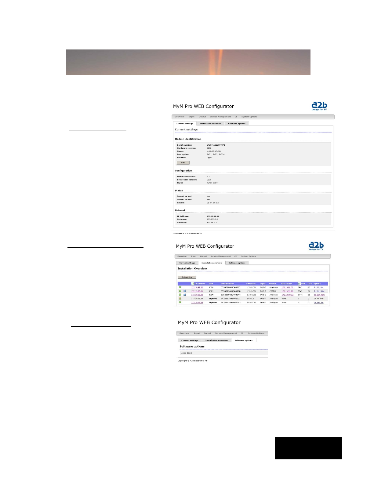
The MyM Pro T2 has an embedded
web server allowing web browser
Internet Explorer to connect to the
unit for settings and management.
No controller software is needed. The
MyM Pro T2 has by default static IP
address(es) for connecting your PC to
the unit.
NOTE! MyM Pro T2 is only
approved with Internet Explorer
as web browser.
The MyM Pro T2 is delivered with the
default IP address: 192.168.0.20 for
port 1 and 192.168.0.21 for port 2 in
6T.
First time installation requires that you
set a static IP address on your
computer. For example set your PC to
IP address: 192.168.0.19 and Net
mask: 255.255.255.0
English
4 IP settings
TCP/IP settings for Windows XP (setting your PC to 192.168.0.19)
Select ”Start”, ”Control panel” and ”Network connections”. Next select “Network
and Internet settings”. ”Right click” on [Settings for local network] and select
[Properties].
In Properties select [Internet protocol
(TCP/IP)] and [Properties].

77
English
Select [Use this IP adress] and write:
192.168.0.19 and select [Net mask]
255.255.255.0. Click [OK] and then click
[Close].
NOTE! For PC with other Operating
Systems (OS) than Windows, please
consult the Owners manual for your PC
for [IP/Network settings].
Connecting your PC to the MyM Pro T2
Connect the MyM Pro T2 double power cords to a
wall outlet.
See section 6 for installation.
Next connect your PC to the MyM Pro T2 with a
network cable.
Start your web browser 1) and write the IP address
192.168.0.20 and 192.168.0.21 for second port *)
in the address field of your browser.
1) MyM Pro is only approved with Internet
Explorer
Settings of IP address
Click the [System options]
menu and then press [IP
Settings] to set a new IP
address, Netmask and
Gateway for the MyM Pro T2.
4 IP settings (continued)
*) MyM Pro 6T

8
English
5.1 Overview menu
Current settings
Contains information of current
input and output signals, if the
tuners are locked to a signal,
firmware version, bootloader
version, hardware revision, serial
number and current IP Network
settings.
All necessary settings can be made in the web GUI via a web browser. When first
connection is made with the MyM Pro T2 following overview menu will appear.
5 Menus and settings
Software options
In this menu you can see
which software options that
are activated.
To continue with settings click the [Input] name in the banner.
Installation overview
In this menu you can see all MyM
Pro units when connected to a
switch and also see EXM/OXM
units that are connected to the
same switch.

99
English
5.2 Input settings
As the MyM Pro T2 contains
”multituner” start by
selecting either DVB-T/T2 or
DVB-s/S2. After that you
choose [Tuner 1] or [Tuner
2] for settings of the tuner
parameters.
Tuner 1 provides the service
list for RF output Ch1 and
Ch2. Tuner 2 provides the
service list for RF output
Ch3.
[Bandwidth] can be
selected between 6, 7 or 8
MHz. Select input channel
from [Channel name] scroll
list or write the center
frequency of the wanted Mux
and press [Set].
If you have an MyM Pro 6T
proceed with next two tuners
[Tuner 3] and [Tuner 4]
after moving the TP cable to
the other RJ 45 port (if not
using switch). Tuner 3
provides the service list for
RF output Ch4 and Ch5.
Tuner 4 provides the service
list for RF output Ch6.
NOTE! Don’t press [Set] if
channel is chosen from
the scroll list.
5 Menus and settings (continued)

1010
English
5.2 Input settings cont.
For receiving from satellite, start
with chosing [Tuner 1] or
[Tuner 2]. Tuner 1 provides the
service list for RF output Ch1
and Ch2. Tuner 2 provides the
service list for RF output Ch3.
The tuner can also be
”Disabled”.
Select the actual Input
parameters for the satellite
transponder you receive.
After the tuner has locked you
can read the values for
[Locked], [Level] and [C/N].
If you have an MyM Pro 6S
proceed with next two tuners
[Tuner 3] and [Tuner 4] after
moving the TP cable to the other
RJ 45 port (if not using switch).
Tuner 3 provides the service list
for RF output 4 and 5. Tuner 4
provides the service list for RF
output 6.
5 Menus and settings (continued)

11
English
5.3 Output settings
Modulation
Band
Start the output setup by selecting
which band you want to use. You can
select VHF-7, VHF-8 and UHF. VHF-7
and VHF-8 corresponds to 7 and 8 MHz
bandwidth. After selection press [Set].
Frequency
For each of the 3 (or 6) possible RF
output channels, set the desired output
channels by using [Channel name]
scroll list or write the frequency.
NOTE! The MyM Pro provides DSB
modulation so you can’t use
adjacent channels.
National
Subtitle/
Type
Set type of subtitling to Normal or for
Hearing Impaired or None.
Language
Select subtitling language. Depends of
received languages in the terrestrial
signal.
Priority
Set DVB or Teletext subtitling as default
selection.
Audio/Video Delay (ms)
This is automatic. However, if you
experience a lip-sync delay problem you
can set delay between 200ms and -
200ms individually for each Channel
5 Menus and settings (continued)

12
English
Advanced
Aspect ratio
Set correct picture format of the
programs transmitted from the MyM Pro
T2.
Video standard
Select your regional video standard.
Audio system
Set your regional audio standard.
Video watchdog
Here you can switch the video WD On or
Off. This can be useful for example if
authorisation of a new smartcard is hard
to achieve. A non used channel shall be
set to “OFF” to avoid rebooting of the
unit.
NOTE! Changing this setting will
only take effect if a reboot is done
after the change.
5 Menus and settings (continued)
5.3 Output settings
continued
National (continued)
Auto conversion
Setting this in position “On”
converts subtitling to fit actual
picture aspect ratio if needed.
Teletext Charset
Select appropriate characters for
selected language.
Audio/
Audio language
Select which language to receive
and transmit on the outgoing
programs.
Audio level
This setting allows to equalise the
difference in sound level between
different programs. Settings can be
done between +6 and -6 dB.

13
English
5.4 Service Management
The MyM Pro 3T contains 2 and for MyM Pro 6T 4 separate DVB-T tuners and totally 3 or 6
services can be selected for each of the output channels, named [CH-1], [CH-2] and [CH-
3] and for MyM Pro 6T also [CH-4], [CH-5] and [CH-6].
The list of services presents all received services from both tuner inputs. Service from
Tuner 1 is named “Tuner1” and services from Tuner 2 is named “Tuner2” respectively
“Tuner 3” and “Tuner 4” in a 6T.
When one program (service) is selected, the box in front of the program name changes
colour to green. The service list gives following information:
Selected service Green colour indication
Type Shows type of service (MPEG-2, MPEG-4, Data etc.)
Name Program name
Provider Name of operator
Input Indicates what tuner input the service is received from.
SID Service ID number (as received)
Hanglock Shows if service is encrypted or not and if CAM is inserted
Status Icons for Analogue out and watchdog enabled
Count Counts if there is a fault in the video decoding
5 Menus and settings (continued)
NOTE! To detect whether a Common Interface module and
smart card actually decrypts the programs is only possible
by watching the outgoing signal on a TV-set tuned to the
correct frequency.

14
English
5.5 CI menu
The MyM Pro 3T contains 2 CI (Common
Interface) and MyM Pro 6T contains 4 CI
(Common interface). [CI-1] decrypts
services for output CH-1 and CH-2. The
[CI-2] decrypt services for output
CH-3.
In MyM Pro 6T [CI-3] decrypt services
for CH-4 and CH-5 and [CI-4] decrypt
service for CH-6In menu you get
information about CAM and card.
In the Advanced settings menu you can
change timing settings for the used
CAM if there is a need for changing
that. After a change is made the
[Save] button must be clicked. If
changes are made and does not work,
you can get the default settings again
by a click on the [Reset] button and a
click on the [Save] button.
NOTE! If one change CAM to
another CA system (i.e. from NDS to
Conax) the unit needs to be
rebooted. Decryption may take
some seconds before it starts.
5 Menus and settings (continued)

15
5.6 System options
Upload/Upgrade
The Upgrade menu is used to be able
to download software Upgrades or
future software functionality.
The procedure of downloading a new
software looks as described below:
1.Download the appropriate file from
our web page to your PC.
2.Browse for the file in the MyM Pro T2
user Interface.
3.Press [Upload]
4.Wait until message shows up,
“Upload completed”.
5.Click on [Restart] to reboot the
MyM Pro T2.
The Upload menu shows current files
downloaded into the units and can be
useful when contacting A2B support.
Uptime
The Uptime menu gives statistics of
uptime and possible restarts. The log
can be cleared by click on [Clear log].
IP settings
This section shows current IP-address,
Netmask and Gateway settings.
Remember to change settings if the
default IP-address is used by other
devices in your network.
In case you have forgotten your IP-
address please consult the A2B
support web site and download free of
charge our tool “IP-supporter”. This
tool finds all MyM Pro T2 and their
respective IP-addresses available in
your network.
Also remember to press [Apply
settings] when ready.
Reboot MyM
Pressing [Reboot unit] re-starts the
MyM Pro T2. All settings are preserved
so no settings or programs will be lost.
English
5 Menus and settings (continued)

1616
The MyM Pro T2 can be installed either as a stand alone unit directly on the wall by the
use of a dedicated MyM Pro T2 Wall Mount brackets (part number 702800.10) or in an
19 inch cabinet.
Before connecting power to the MyM Pro T2, make sure that all other connections have
been made. A coaxial cable of good quality with an F-connector should be connected to
the Antenna input and another one from the RF output to the SMATV network.
Make all necessary settings as described in section 4 and 5.
English
Accessories
6 Installation and configuration
Installation with MyM Pro 3T
Wall Mount kit 1 unit.
MyM Pro 3S/6S
Wall Mount kit 3
units (for two MyM
and one switch)
including screws
and nuts.
Art no: 121403.10
Accessories
MyM Pro 3S/6S Wall
Mount kit 1 unit
including screws
and nuts
Art no: 121401.10
MyM Pro 3S/6S Wall
Mount kit 2 units
including screws
and nuts
Art no: 121402.10

1717
English
2 / 4 x DVB-T Terrestrial Receiver
3 / 6 x Modulator
3 / 6 x MPEG Decoder – Video - audio
Miscellaneous
AC Power supply 230 VAC typ (94-264VAC)
AC power consumption 3T Typ. 18 W
AC power consumption 6T Typ. 36 W
Ethernet port Setup and update
Setup Web based GUI
Dimension 383x220x44 mm (excl.
connectors)
Weight Approx. 3,2 kg
Operating temperature -20 to +45°C non
condensing
Modulation standard PAL B/G, I, D/K, SECAM
(DSB)
Audio FM-mono, NICAM stereo
and A2/A2* stereo
Output channels Double side band from
160 – 862 MHz.
Output level Min. 80 dBμV, fixed
RF output connector Type F female, 75 Ω
Number of tuners 2/4 T2
Input frequency 47- 862MHz
Connector Type F female, 75 Ω
Input level 40 – 70 dBuV
Bandwidth Selectable 6,7 or 8 MHz
FEC Auto
GI Auto
Modes 2k and 8k
Video standard MPEG2 MP@ML, MPEG4
h.264 AVC MP@L3
Audio standard AAC HE or MPEG 1
layer II
Picture aspect ratio Letterbox, Anamorphic
Teletext VBI
Subtitling Teletext or DVB subtitling
Decryption
Decryption Interface 2/4 x Common Interface
(PMCIA 5VDC)
Decryption type Single or Multidecryption
CAM’s supported
CI 1 slot (3/6T) Decryption for output Ch1
and Ch2
CI 2 slot (3/6T) Decryption for output Ch3
CI 3 slot (6T) Decryption for output Ch4
and Ch5
CI 4 slot (6T) Decryption for output Ch6
Example of MyM Pro T2 Web GUI
7 Technical specification MyM Pro T2

1818
The document for Declaration of Conformity is available for
download from www.a2b.se.
Further information at www.a2b.se.
English
8 Declaration of Conformity

19
English
DVB Digital Video Broadcasting (Standardization body)
MPEG-2 Compression format for digital TV
MPEG-4 Compression format for digital TV (SD and HD)
DSB Double Side Band (RF modulation occupying 2 channels)
NICAM Digital sound format for analogue TV transmission
IP Internet Protocol (defines how data is packetized for Internet broadcast)
DVB-S Modulation format (QPSK) for satellite transmission of digital TV
DVB-S2 Modulation format (QPSK or 8PSK) for satellite transmission of digital TV
DHCP Dynamic Host Configuration Protocol is a protocol used by networked devices
(clients) to obtain the parameters necessary for operation in an Internet
Protocol network. This protocol reduces system administration workload,
allowing devices to be added to the network with little or no manual
configuration.
Common Interface Connector for a PCMCIA module used for decrypting encrypted TV programs.
Modules should comply with the DVB CI standard
SD Standard definition TV (576i in Europe)
SMS Service Management System (system for handling smartcards).
SMATV Satellite Master Antenna TV.
A2 Dual sound analogue stereo audio
LNB Low Noise Block (outdoor unit for sat. Reception)
GUI Graphical User Interface
QAM Quadrature Amplitude Modulation (digital modulation method)
QPSK Quadrature Phase Shift Keying (digital modulation method)
8 PSK Eight Phase Shift Keying (digital modulation method)
FEC Forward Error corection (digital error correction method for digital
transmissions)
C/N Carrier to Noise ratio (defines the difference in dB between digital signal and
noise level
AAC-HE Digital sound compression standard
VBI Vertical Blanking Interval. Part in video signal non-visible
CAM Conditional Access Module (see above Common Interface)
9 Abbreviations

651453.01 rev A FW 1.0
A2B Electronics AB
P.O. Box 14 • SE-591 21 Motala • Sweden
Phone +46 141 229100 • Fax +46 141 229101
E-mail [email protected]
www.a2b.se
655312.01 Rev F FW 2.1SR4
Table of contents
Other A2B Electronics TV Receiver manuals
Popular TV Receiver manuals by other brands

Sylvania
Sylvania SRT702A operation instruction

Samsung
Samsung DTB-9401F Instructions for use

Grundig
Grundig P 37 - 830 text Supplemental service manual

Planet Networking & Communication
Planet Networking & Communication DTR-100DB Quick install guide

Denver
Denver DTB-131 user manual

Igloo
Igloo DT840INZ user guide