Using a Double DIN Dash Kit:
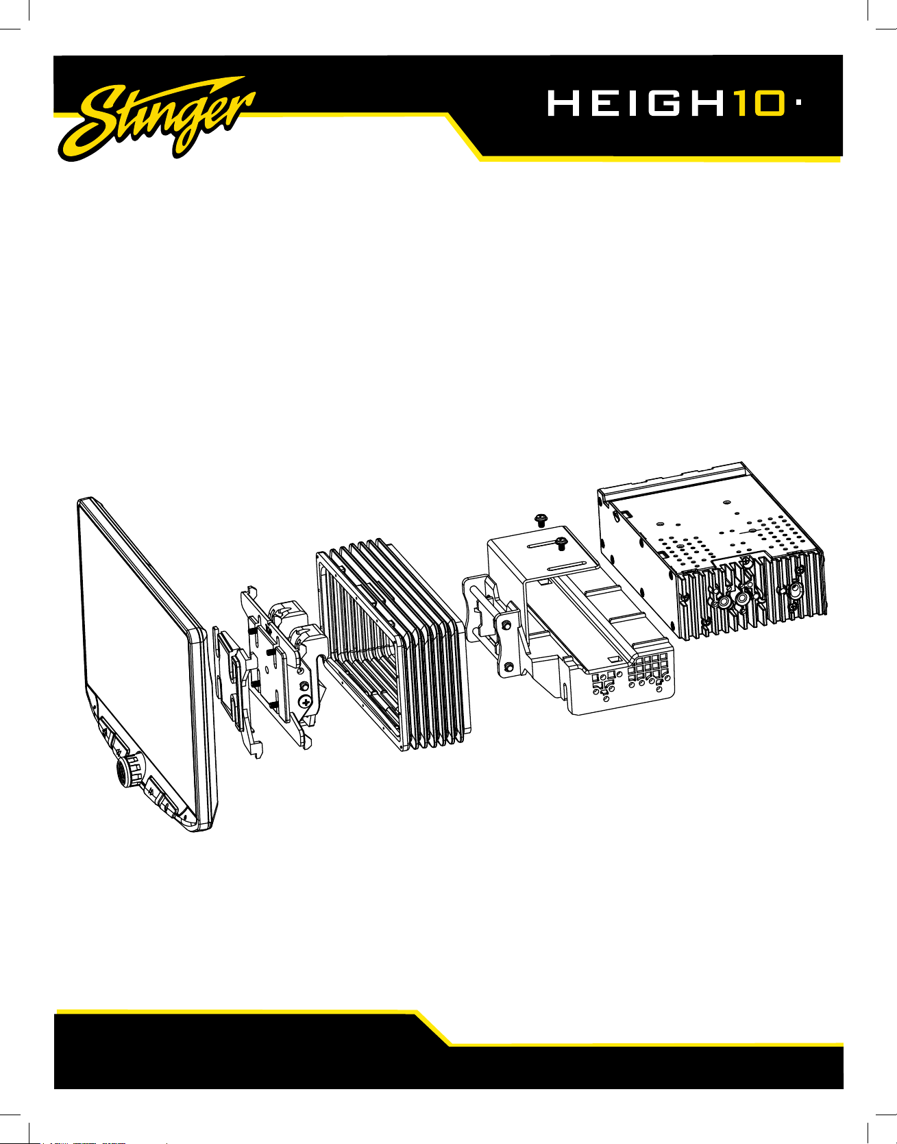
Radio chassis mounts to the brackets attached to the kit main frame
NOTE: BOOT AND DASH KIT NOT SHOWN
4A
FIG. E
FIG. G
FIG. F
9
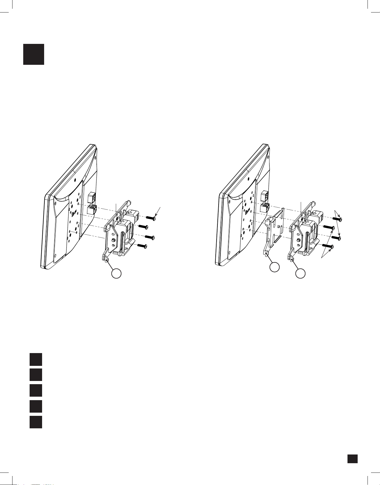
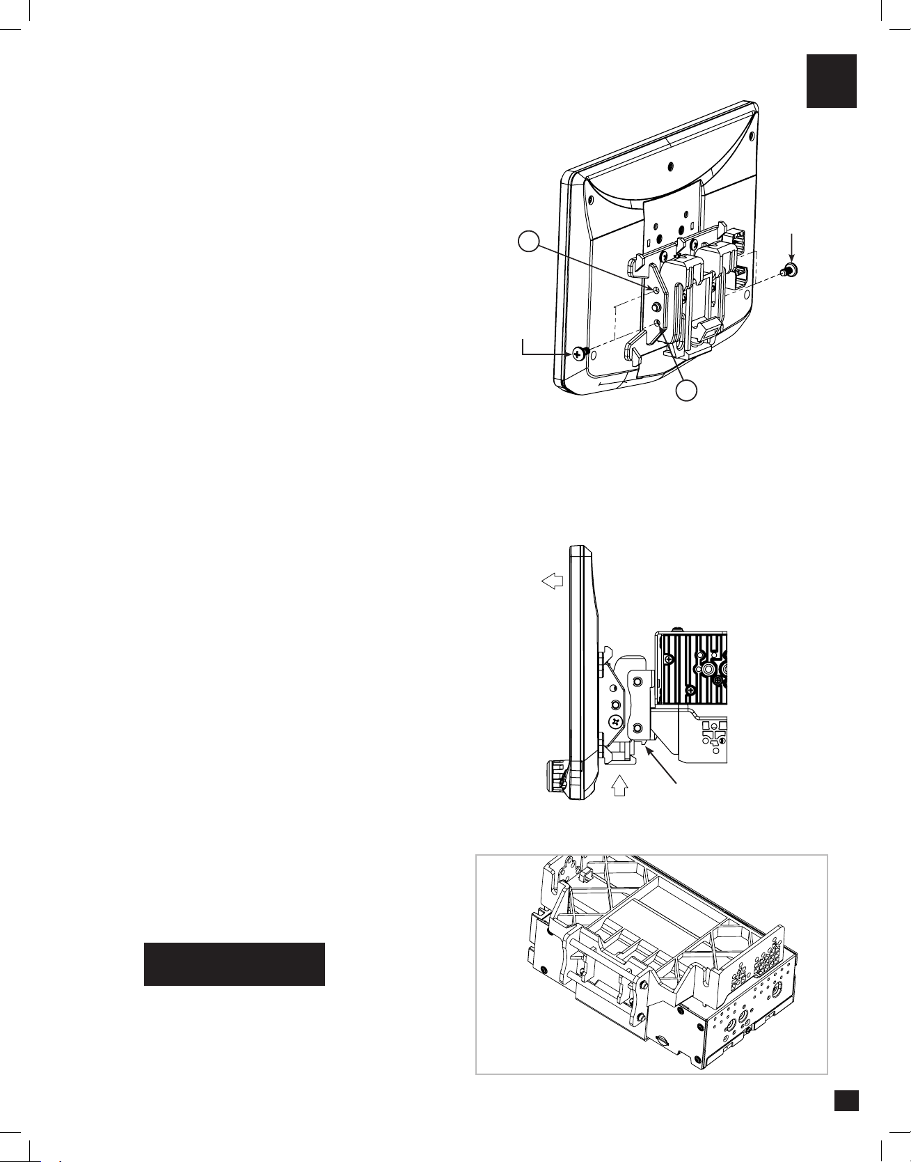
4. Determine the desired position of the display:
a. Display can be vertical or tilted up (FIG. E)
b. Display can slide up or down (Page 7)
c. Display can be tilted horizontally (Page 7 – FIG. B)
Note: There are multiple mounting holes on
the mounting bracket to allow adjusting the
mounting depth. You may drill additional holes
in the mounting bracket and/or the dash kit
brackets to align the display in the best position
and ensure you can use all 8 mounting screws.
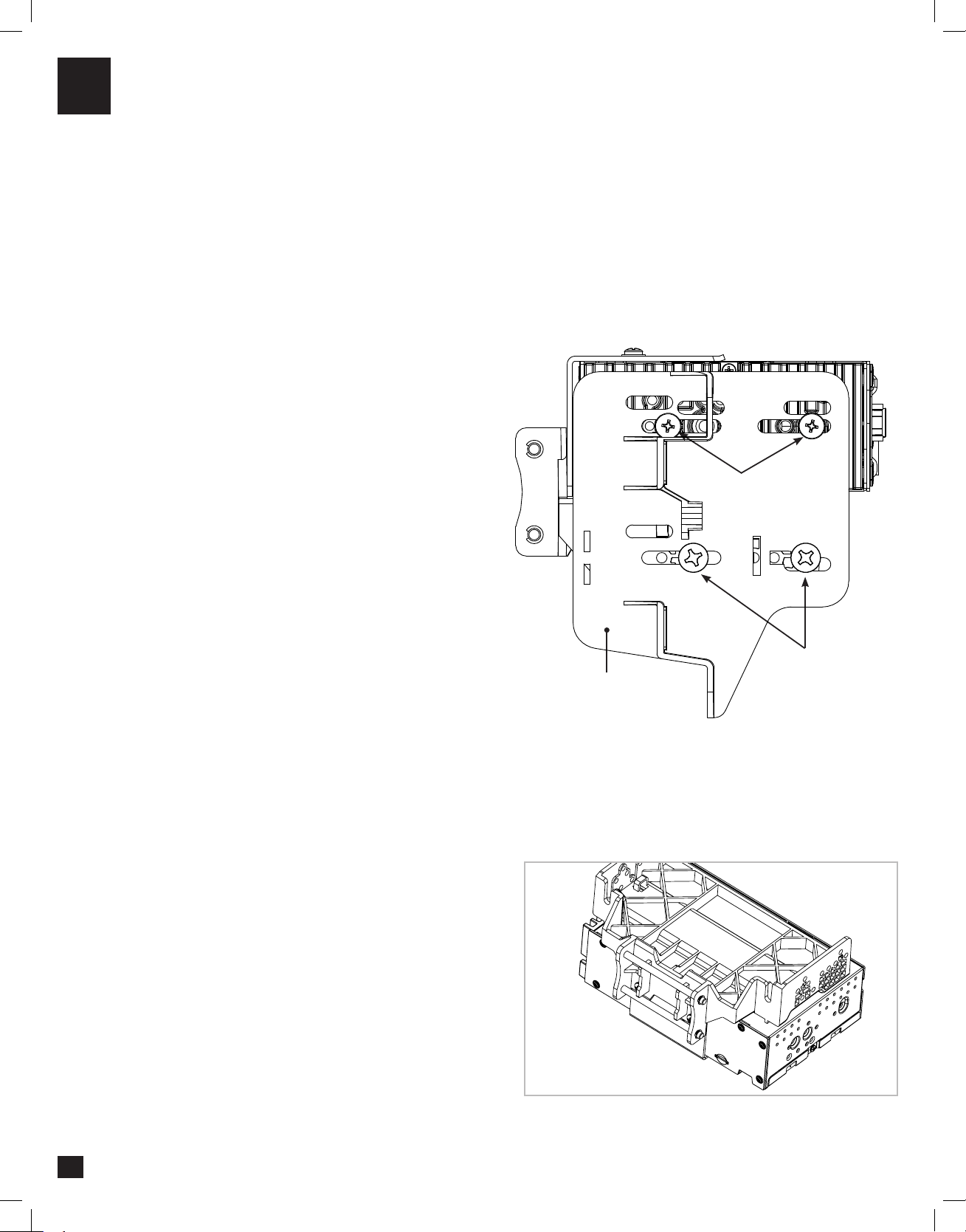
5. Once in the desired position, tighten screws
to the radio chassis (top) and mounting bracket
assembly (bottom).
Note: If the display prevents the factory dash
panel(s) from being installed last, do not push
the display all the way up against the dash
kit. Leave enough bottom gap as the display's
bottom edge rotates towards the dash kit.
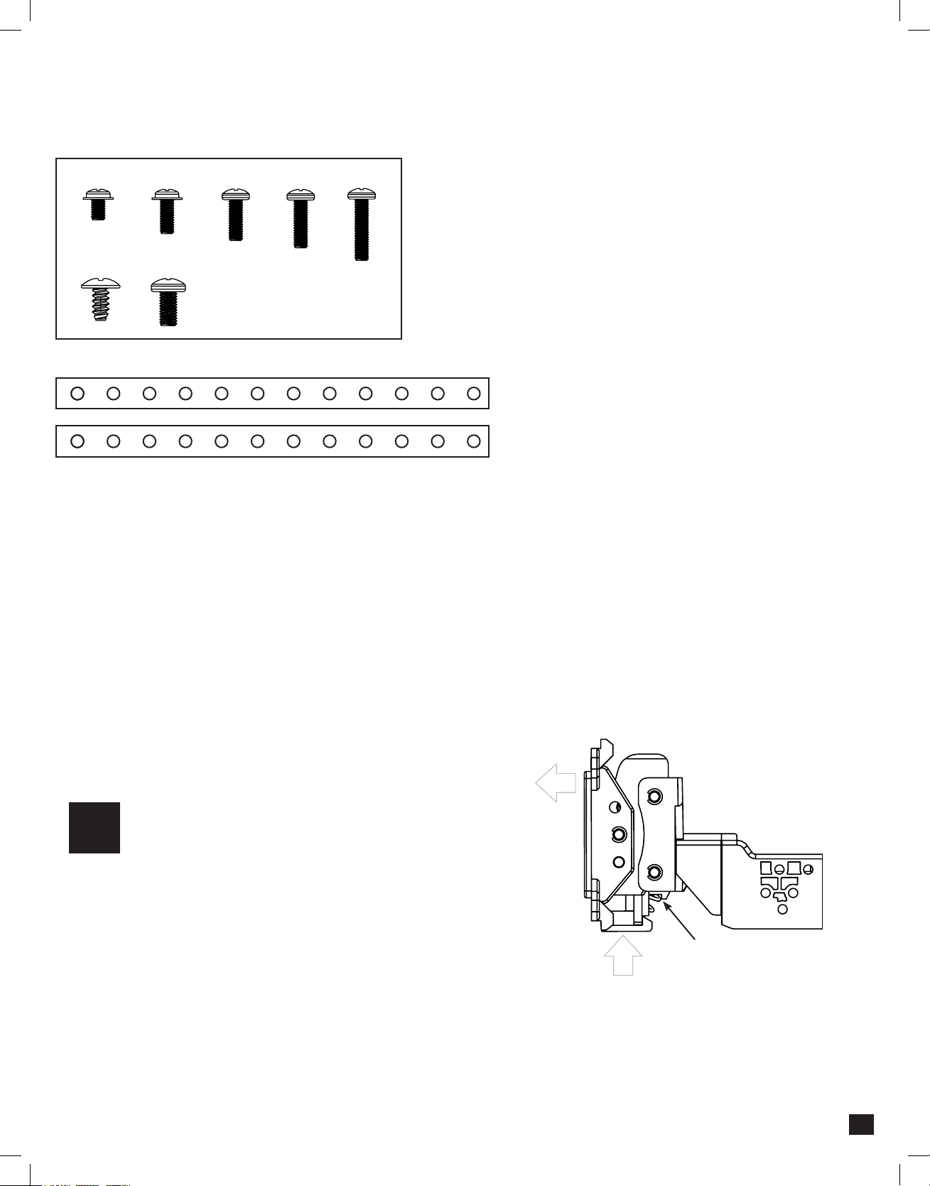
6. Remove the display from the bracket
assembly by pushing up from compression
spring side (1) and swing out to unhook top (2).
(FIG. F)
Note: If there is a depth issue with the radio
module in the top position, move it to the
bottom location by inverting the mounting
bracket assembly. (FIG. G)
VERTICAL TILT: Use Hole A for no vertical
tilt or Hole B for 8 degrees of vertical tilt.
Insert a M5 X 10 on each side of the clamp
assembly at desired tilt.
A
M5 X 10
M5 X 10
Compression Spring
PROCEED TO STEP 5
on Page 16
B