A&D AD-4411 User manual

1WMPD4004595

WARNING DEFINITIONS
The warnings described in this manual have the following meanings:
A potentially hazardous situation which, if not avoided, could result in
death or serious injury.
A potentially hazardous situation which, if not avoided, may result in
minor or moderate injury or damage to the instrument.
This symbol indicates caution against electrical shock. Do not touch
the part where the symbol is placed.
This symbol indicates the ground terminal.
This symbol indicates that an operation is prohibited.
NOTE Information or cautions to use the device correctly.
© 2022 A&D Company, Limited. All rights reserved.
No part of this publication may be reproduced, transmitted, transcribed, or translated into any
language in any form by any means without the written permission of A&D Company, Limited.
The contents of this manual and the specifications of the instrument covered by this manual are
subject to change for improvement without notice.
Product names and company names mentioned in this manual are trademarks or registered
trademarks of their respective companies in Japan or other countries and regions.

3 AD-4411
Contents
1. Introduction ....................................................................................................................5
1.1. Safety precautions.....................................................................................................5
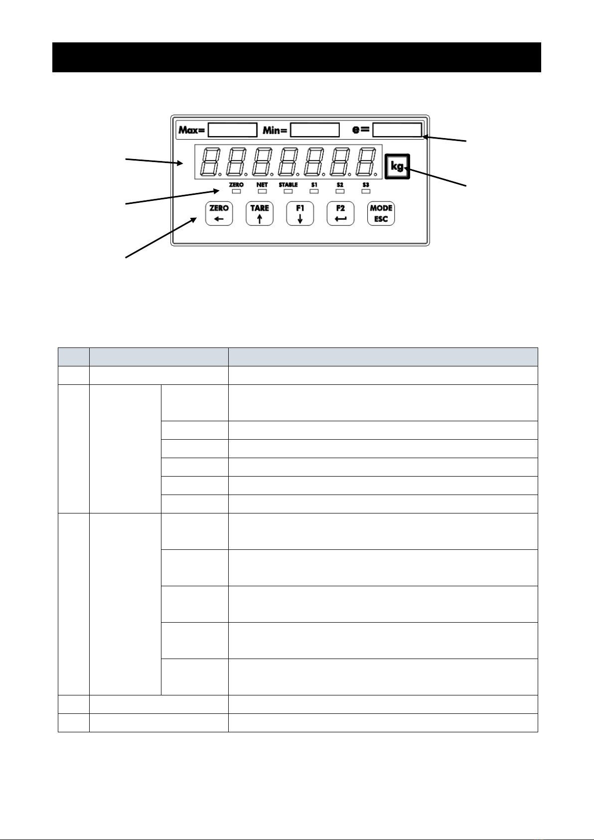
2. Part names.....................................................................................................................6
2.1. Front panel.................................................................................................................6
2.2. Rear panel .................................................................................................................7
2.3. Accessories ...............................................................................................................7
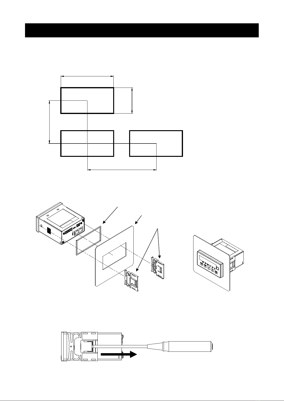
3. Installing to the control panel..........................................................................................8
3.1. Installing the indicator to the control panel.................................................................8
3.2. Removing the indicator from the control panel ..........................................................8
4. Connection to power supply ...........................................................................................9
4.1. DC power supply assignment ....................................................................................9
4.2. Connection diagram...................................................................................................9
5. Connection to load cell .................................................................................................10
5.1. Load cell input terminal assignment.........................................................................10
5.2. Connection diagram.................................................................................................10
6. Operation mode............................................................................................................12
7. Calibration ....................................................................................................................13
7.1. Settings required before calibration .........................................................................13
7.2. Digital calibration .....................................................................................................13
7.3. Actual load calibration..............................................................................................14
8. Basic functions .............................................................................................................17
8.1. Main display.............................................................................................................17
8.2. Power-on zero .........................................................................................................17
8.3. Zero-setting..............................................................................................................18
8.4. Zero tracking............................................................................................................18
8.5. Tare .........................................................................................................................18
8.6. Gross / Net display selection ...................................................................................18
8.7. Center-zero detection ..............................................................................................19
8.8. Stability detection.....................................................................................................19
8.9. High resolution display selection..............................................................................19
8.10. Comparator............................................................................................................19
9. Industrial Ethernet ........................................................................................................20
9.1. EtherNet/IP (AD-4411-EIP)......................................................................................20
9.2. PROFINET (AD-4411-PRT).....................................................................................22
9.3. EtherCAT (AD-4411-ECT) .......................................................................................23
9.4. Cyclic data layout.....................................................................................................24
10. USB............................................................................................................................28
10.1. Communication specification .................................................................................28
10.2. Coil data address...................................................................................................29
10.3. Holding register data address................................................................................30
11. Checking software version / hardware .......................................................................34
11.1. Checking software version.....................................................................................35
11.2. Checking display....................................................................................................35
11.3. Checking key switches ..........................................................................................35
11.4. Checking load cell input.........................................................................................35
12. Troubleshooting..........................................................................................................36
12.1. Hardware error.......................................................................................................36
12.2. Checking the connection to load cell with using a multimeter................................37
12.3. Check list ...............................................................................................................38
13. Initialization.................................................................................................................39
14. Setting functions.........................................................................................................40

AD-4411 4
14.1. Setting calibration function.....................................................................................41
14.2. Setting general functions .......................................................................................42
15. Function setting lists...................................................................................................44
15.1. Calibration function list...........................................................................................45
15.2. Digital calibration function list.................................................................................45
15.3. Basic function list ...................................................................................................46
15.4. IP function list ........................................................................................................47
15.5. EtherCAT function .................................................................................................47
16. Specifications .............................................................................................................48

5 AD-4411
1. Introduction
The AD-4411 is a weighing indicator that converts signals from strain gauge load cells and connects them to
an Industrial Ethernet network. It contributes to an efficient system by connecting weighing instruments to
industrial control systems in plants and factories.
- Two communication ports enable daisy-chain connection without a switching hub.
- 7-segment green LED display with a character height of 10 mm and display resolution of ±999999.
- High-speed AD conversion of 1200 times/second and a digital filter enable high speed and accurate weighing.
- DIN96x48 panel mount type with IP65 protection on the front panel.
- Settings can be updated with a PC via a USB port.
1.1. Safety precautions
Please read the following precautions carefully before using this product.
・Provide an external safety circuit for the indicator so that the safety of the whole system can be
secured even if errors occur in the external power supply or the indicator.
・Do not use the indicator in the following environments:
- where the temperature and the humidity exceed the specifications
- where there are corrosive or flammable gases
- where the indicator could be subjected to oil, chemicals, or water
Please note that securing the indicator to the control panel provides IP65 protection to the outside of
the control panel.
・Turn off all external power supplies when installing or removing the indicator.
・Turn off all external power supplies when wiring the indicator.
・Be sure to ground the indicator.
・Do not clamp control wires or communication cables with power lines, and do not position them close
to power lines.
・Position the load cell cable a sufficient distance away from high frequency circuits such as high voltage
power lines or inverter load circuits.
WARNING
CAUTION

AD-4411 6
2. Part names
2.1. Front panel
No. Name Description
(1)
Main display
Displays
the
measured value and various settings.
(2) Status LEDS
ZERO The LED is ON when the measured value is within 1/4 of
the minimum
division
NET
The LED is ON when the net value is displayed.
STABLE The LED is ON when the measured value is stable.
S1
The LED is ON when the S1 status ON condition (FncF07) is met.
S2 The LED is ON when the S2 status ON condition (FncF08) is met.
S3
The LED is ON when the S3 status ON condition (FncF09) is met.
(3) Key switches
ZERO/←Zeros the gross value.
Moves the blinking digit to the left when not in measurement mode.
TARE/↑Performs tare.
Increases the blinking digit by one when not in measurement mode.
F1/↓Performs the function set for the F1 key function (FncF05).
Decreases the blinking digit by one when not in measurement mode.
F2/ENTER Performs the function set for the F2 key function (FncF06).
Updates the setting value entered when not in measurement mode.
MODE/ESC Changes the operation mode.
Cancels the setting value entered when not in measurement mode
(4)
Capacity label
Attach the included capacity label if necessary.
(5) Unit label Attach the included unit label if necessary.
(1)
(2)
(3)
(4)
(5)

7 AD-4411
2.2. Rear panel
No. Name Description
(1)
DC power input terminals
Terminals for connection of a DC24V power supply
(2) Load cell input terminals Terminals for connection of load cells.
(3)
USB connector
Connector for connection with setting PC. (Type-C)
(4) Industrial Ethernet status LEDs
Indicate Industrial Ethernet status.
(5) Industrial Ethernet connector Connector for connection of PLC via Industrial Ethernet. Dual ports
can be used for daisy chain wiring. (RJ-45)
2.3. Accessories
Name
Type No.
Manufacturer
Qty.
Waterproof packing 1064053659 A&D 1
Panel mounting bracket
1073035116
A&D
2
Capacity label 1084054808 A&D 1
Unit label
1084023456A
A&D
1
Power connector MC 1,5/ 3-ST-3,81 Phoenix Contact 1
Load cell connector
MC 1,5/ 7-ST-3,81
Phoenix Contact
1
(2)
(1)
(3)
(4)
(5)

AD-4411 8
3. Installing to the control panel
3.1. Installing the indicator to the control panel
Make a hole in the control panel of the dimensions shown in the figure below. When installing more than one
indicator, make sure there is sufficient space around each unit for heat dissipation.
Attach the waterproof packing to the main body, then insert the main body into the control panel from the front.
Fit the left and right mounting brackets into the grooves of the case and slide them all the way into the panel.
3.2. Removing the indicator from the control panel
While lifting the latch of the panel mounting bracket from the case using a flat head screwdriver or similar tool,
slide the bracket towards the rear of the case.
92
+0.8
0
45
+0.6
0
120
75
Panel thickness: 1.6 to 3.2
Unit: mm
Control panel
Waterproof packing
Panel mounting brackets

9 AD-4411
4. Connection to power supply
4.1. DC power supply assignment
Symbol Description
+
DC power input + (24V)
- DC power input - (0V)
Functional ground
Applicable wire
Item
Specifications
Wire size 0.14 to 1.5 mm²(AWG 26 to 16)
Wire strip length
7 mm
Tightening torque 0.22 to 0.25 Nm
4.2. Connection diagram
Attach the included power connector accessory and wire as shown below.
24V
0V

AD-4411 10
5. Connection to load cell
5.1. Load cell input terminal assignment
Symbol Description
SIG-
Load cell signal input -
SIG+ Load cell signal input +
EXC-
Load cell excitation voltage -
SEN- Sensing input-
SEN+
Sensing input+
EXC+ Load cell excitation voltage +
SLD
Shield
Applicable wire
Item
Specifications
Wire size 0.14 to 1.5 mm²(AWG 26 to 16)
Wire strip length
7 mm
Tightening torque 0.22 to 0.25 Nm
5.2. Connection diagram
Attach the included load cell connector accessory and wire as shown below.
4-Wire type
Set load cell connection type (CALF17) to 0: 4 wire type (default = 1: 6 wire type).

11 AD-4411
6-wire connection
Set load cell connection type (CALF17) to 1: 6 wire type (default).
When you connect the load cells in parallel, use a summing box. Connecting AD-4411 to four load cells is as
shown below.
Signal -
Summing Box
Shield
Power supply+
Power supply -
Signal +

AD-4411 12
6. Operation mode
Display all on and off
Measurement mode
Power on
General function mode
Calibration function mode
Check mode
Initialization mode
Mode selection
Press for 3s or more
Reset
Actual load calibration mode
Digital calibration function
mode

13 AD-4411
7. Calibration
Calibrate the AD-4411 so that it can properly convert the signal from the load cell to a load value.
7.1. Settings required before calibration
Before calibration, the following settings are required.
・Select the measurement unit (CALF01).
The set unit is only used for external communication. Attach the unit label to the main display.
0: None / 1: g / 2: kg (default) / 3: t
・Select decimal point position (CALF02).
0: 0 (None) (default)
1: 0.0
2: 0.00
3: 0.000
4: 0.0000
5: 0.00000
・Set the minimum division (CALF03).
1: 1d (default) / 2: 2d / 3: 5d / 4: 10d / 5: 20d / 6: 50d
・Set the maximum capacity (CALF04). (Default=999999)
7.2. Digital calibration
After calibration using calibration weights is completed, digital calibration function settings are automatically
updated.
Be sure to make a note of the updated settings so you can re-calibrate without applying actual load if the
AD-4411 is replaced.
・Load cell input signal at zero calibration (dCAL01)
・"Load cell input signal at span calibration"-"Load cell input signal at zero calibration"(dCAL02)
・The calibration weights at span calibration (dCAL03)

AD-4411 14
7.3. Actual load calibration
Refer to "6 Operation mode" to move to actual load calibration mode,
then press the [F2/ENTER] key.
7.3.1. Zero calibration
Press the [F2/ENTER] key.
If the [F1/↓] key is pressed, the indicator skips zero calibration and
enters span calibration.
The current load cell input signal (mV/V) is displayed.
Check that the STABLE status is ON.
Press the [F2/ENTER] key to execute zero calibration.
If zero calibration fails, "C ErrX" is displayed.
Refer to "7.3.3 Error in actual load calibration" for error details.
If zero calibration is successful, "PASS" is displayed, and zero
calibration is completed.
Press the [F2/ENTER] key to enter span calibration.
Or press the [MODE/ESC] key four times to return to measurement
mode.
× 4

15 AD-4411
7.3.2. Span calibration
Press the [F2/ENTER] key.
If the [F1/↓] key is pressed, the indicator skips span calibration and
enters zero calibration.
Set a calibration weight value by the following key operations
[ZERO/←] key: Moves the blinking digit to the left.
[TARE/↑] key: Increases the blinking digit by one.
[F1/↓] key: Decreases the blinking digit by one
[F2/ENTER] key: Confirm the setting value.
The current load cell input signal (mV/V) is displayed.
Place the calibration weight or apply load to the load cell.
Check that STABLE status is ON.
Press the [F2/ENTER] to execute span calibration
If span calibration fails, "C ErrX" is displayed.
Refer to "7.3.3 Error in actual load calibration" for error details.
If span calibration is successful, "PASS" is displayed, and span
calibration is completed.
Press the [MODE/ESC] key four times to return to measurement mode.
Or press the [F2/ENTER] to enter zero calibration again.
× 4

AD-4411 16
7.3.3. Error in actual load calibration
Error code Description
The load cell signal voltage at zero calibration exceeds 7.0 mV/V.
Check that the load cell is connected correctly.
The load cell signal voltage at zero calibration is less than -7.0 mV/V.
Check that the load cell is connected correctly.
The calibration weight value for span calibration exceeds the maximum capacity.
Set the calibration weight value to the maximum capacity or less.
The calibration weight value for span calibration is below the scale interval.
Set the calibration weight value to the scale interval or more.
The load cell input signal at span calibration is smaller one at zero calibration.
Check that the load cell is connected correctly.
The load cell signal voltage at span calibration exceeds 7.0 mV/V.
Check that the load cell is connected correctly.

17 AD-4411
8. Basic functions
After AD-4411 is turned on, all segments of the display turn on / off to check the display. Then AD-4411 enters
measurement mode and starts measuring.
Refer to "14 Setting functions" for function setting methods.
8.1. Main display
The following content is displayed in measurement mode.
・Measurement value.
・Positive overload.
The gross value exceeds the maximum capacity by +8d.
・Negative overload.
The gross value meets the negative overload condition (CALF15).
(Default = 0: Gross < - maximum capacity + 8d)
8.2. Power-on zero
After power-on, the gross value is set to zero automatically when the gross value is within the maximum
capacity ± 10% and stable.
Set power- on zero (CALF14) to 1: Enable (default = 0: Disable) to use this function.
If the condition is not met, "------" is displayed until the condition is met.
Press the [MODE/EXC] key to skip power-on zero and enter measurement mode.

AD-4411 18
8.3. Zero-setting
Executing zero-setting
When the measurement value is within the zero setting range (CALF05), press the [ZERO] key or send a
request externally to save the gross value as the zero setting value and set to zero.
Set the following to use this function.
・Set the zero setting range (CALF05) to a value other than 0 (default = 100%).
・Select the zero setting at unstable (CALF10) from 0: Disable / 1: Enable (default).
Zero clear
Press a key to which zero clear function is assigned or request externally to clear the zero setting value.
Set the following to use this function.
・Set the function of [F1] / [F2] key (FncF05 / Fnc06) to 2: zero clear (default = 0: None).
・Set zero clear (CALF13) to 1: Enable (default).
8.4. Zero tracking
The gross value is set to zero automatically when the tracking time has passed while the gross value is
maintained within the zero tracking width.
Set the following to use this function.
・Set the zero tracking time (CALF06) to a value other than 0.0s (default).
・Set the zero tracking width (CALF07) to a value other than 0: Disable (default).
8.5. Tar e
Executing tare
Press the [TARE] key or request externally, to save the gross value as the tare value and set the net value to
zero.
Set the following to use this function.
・Select taring at unstable (CALF11) from 0: Disable / 1: Enable (default).
・Select taring at the negative gross (CALF12) from 0: Disable / 1: Enable (default).
Tare clear
Press a key to which tare clear function is assigned or request externally to clear the tare value.
Set the following to use this function.
・Set the function of [F1] / [F2] key (FncF05 / Fnc06) to 1: tare clear (default = 0: None).
8.6. Gross / Net display selection
Press a key to which Gross / Net display selection function is assigned or request externally to switch the
displayed value between gross and net. Net status is ON when the net value is displayed.
Set the following to use this function.
・Set the function of [F1] / [F2] key (FncF05 / Fnc06) to 3: Gross / Net display selection (default = 0: None).

19 AD-4411
8.7. Center-zero detection
The center of zero is detected and ZERO status turns ON when the gross value is within 1/4 of the minimum
division.
8.8. Stability detection
Stability is detected and the stable status is ON when the stability detection time has passed while the
measured value is maintained within the stability detection width.
Set the following to use this function.
・Set the stability detection time (CALF08) to a value other than 0.0s (default =1.0s).
・Set the stability detection width (CALF09) to a value other than 0: Disable (default = 2d).
8.9. High resolution display selection
Press a key to which the high resolution display selection function is assigned to switch the displayed value
between high resolution display (10 times higher) and normal display.
Set the following to use this function.
・Set the function of [F1] / [F2] key (FncF05 / Fnc06) to 4: high resolution display selection (default = 0: None).
8.10. Comparator
The comparison value and the measured value are compared, and then Hi / OK / Lo is detected when the
following conditions are met.
Hi
Measured value
>
Upper limit value
OK
Upper limit value
≧
Measured value
≧
Lower limit value
Lo
Lower limit value
>
Measured value
Set the following to use this function.
・Upper limit value (FncF11). (Default = 10)
・Lower limit value (FncF12). (Default = 10)
・Select the target for comparison (FncF13) from 1: Gross (default) / 2: Net.

AD-4411 20
9. Industrial Ethernet
9.1. EtherNet/IP (AD-4411-EIP)
9.1.1. Part names
Name Function Description
NS Network status LED
OFF
No power or no IP address assigned
Green, ON Operating properly
Green, blinking
No connection established
Red, ON IP address duplication
Red, blinking
Communication timeout
MS Module status LED
OFF No power
Green, ON
Operating properly
Green, blinking Scanner in idle state
Red, ON
Unrecoverable fault
Red, blinking Recoverable fault
9.1.2. Communication specifications
Communication is performed according to the following communication specifications.
Note that communication is possible only in measurement mode.
Communication protocol EtherNet/IP (DLR supported)
Transmission speed
10/100 Mbps
Connector RJ-45
Cable specifications
Shielded twisted pair (STP) cable, straight / crossover, CAT 5e or above
Configuration file EDS file (Please download the configuration file from A&D’s website.)
NS
MS
Ethernet port
This manual suits for next models
3
Table of contents