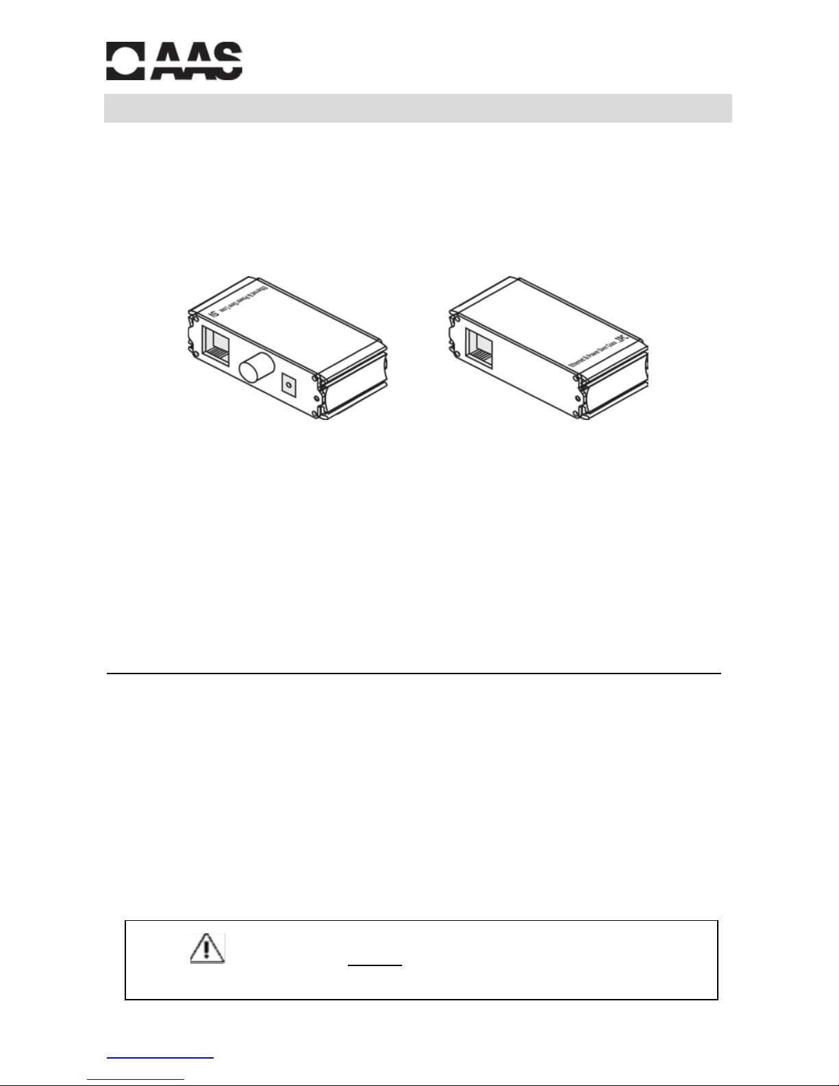
AAS EPOC-POE-100K User manual

Copyright © 2014 AAS Technology N-7
www.AAS.com.tw R201501-V06
User Manual
PoE Ethernet Extender
Over One Coax Kit
EPOC-POE-100K
This Ethernet extender consists of one EPOC-POE-100-SV Unit (host/server side) and one
EPOC-POE-100-IPC Unit (camera side). It can transfer Ethernet signal of IPC-Unit to carrier signal
though coaxial cable or networkcable and extend to SV-Unit, then transfer carrier signal to
Ethe rnet s ignal a nd tra nsmit power synchronously. SV-Unit could use 48~57V DC power s upply
orPoE power supply, which fully meets the needs of long distance Ethernet signal transmission
and power supply. It i s widely used in coaxial cable and networkcable mixed wiring security
surveillance and network rebuildingprojects.
Features ..
•Uses coaxial cable or network ca bles to tra nsmit Ethernet a nd power s ignals
•Max. di stance up to 500m / 1600ft via coaxial cable; 400m / 1300ft via network cable
•Adopt a dvanced tra nsmission and power supply technology
•Ethernet delay less than 1ms; meets point-to-point application
•Standards: IEEE802.3 10BASE-T, IEEE802.3u 100BASE-TX, IEEE802.3af/at
•Protections: Excellent circuit isolation protection, superior product a nti-thunder,
anti-static a nd a nti-interference ca pability
•Appearance: Meets MIT rack installation standard
•Pl ug-and-play, no setting re quired
•48~57V DC powe r s upply (Not included) (EPOC-POE-100-SV)
Please read the Manual before attempting to use this product.
Specifications and appearance are subject to change without notice.
EPOC-POE-100-SV
Host/Server Side
N-7a
EPOC-POE-100-IPC
Camera Side
N-7b

2
Disposal of Old Electrical & Electronic Equipment (Applicable in the European
Union and other European countries with separate collection systems).
This symbol on the product or on its packaging indicates that this productshall not be treated as household
waste.Instead itshall be handedover to the applicable collection point for the recycling of electrical and
electronic equipment. By ensuring this product is disposed of correctly,you will help prevent potential
negative consequences for the environmentandhuman health, which couldotherwise be caused by
inappropriate waste handling of this product.The recycling of materials willhelp toconserve natural
resources. For more detailed information about recycling ofthis product, please contact your local city
office, your householdwaste disposal service or the shop where youpurchased the product.
Caution ..
This product has been tested for conformance to safety regulations and requirements. However,like all
electronic equipment,this product should be usedwith care.Please read andfollow the safety instructions
to protect yourself from possible injury andto minimize the risk of damage to the unit.
1. Handle this product withcare
Avoid any shock or bumping of the product. Improper handling could damage the product. Do not handle
the unit with wet hands. Provideproper ventilation andair circulation and donotusenear water.
2. Requires a properoperating environment
This product is not waterproof and is designedfor indoor use.The allowable temperature rangefor
operation of this productis between 0°C~55°C / 32°F~131°F.
3. Check the power source voltage
The power source voltage should be within the specified range.(Product must meet the specifications).
4. Objects and liquid entry
Never push objects of any kind into this product as this may touch dangerous voltage points of short out
parts that couldresult in a fire orelectric shock.Never spill any kind of liquid on the product.
5. Cleaning
Do not use liquidor aerosol cleaners toclean this unit. Always unplug the power tothe device before
cleaning.
6. Servicing
Do not attemptto service this productby yourself as opening orremoving covers may expose you to
dangerous voltage orother hazards. Refer all service to qualifiedservicing personnel.

3
Package Contents ..
1. One (1) EPOC-POE-100-SV unit (host/server side)
2. Two (2) Ea r Mount Brackets
3. One (1) User Manual
For anyreturns, please include allcomponents listed above with original packaging in Resalable
Condition. Absolutely No Returns wi ll be a ccepted i f any component is missing/damaged.
Parts & Functions ..
EPOC-POE-100-SV (Host/Server Si de): EPOC-POE-100-IPC (Camera Side):
LED Status
PoE In / Out (RJ-45)
EPOC RJ-45
Yellow light
Green light
Yellow / Green light
Flash
n/a
Indicate communicating
n/a
On
Indicate PoE output / DC
power supply
Indicate cable connecti on
Indicate cable
connectionis normal
1. One (1) POEOC-100-I PC unit (camera side)
2. Two (2) Ea r Mount Brackets
3. One (1) User Manual

4
Application Diagram ..
Hardware Installation ..
1. Pleaseturn off thesignal source and the device's power; installation with power still
on maydamage the device.
2. Use network cable to connect PoE INport of SV-Unit and PoE Ethernet switch (if it's
not PoE s witch,then need to use 48-57V p ower s upply for SV-Unit).
3. Use another networkcable or coaxial ca ble to connect Ethernet portof SV-Unit a nd
Ethernet port of IPC-Unit
4. Use a network ca ble to connect IP camera with PoE OUT port of IPC-Unit.
5. Check if the installation is correct a nd devi ce is good; make sure all the connections
a re reliable and power for the system.
6. Make sure every network device haspower s upply and is working normally.
** Ta ble 1 (The test data in Ta ble 1 based onthetest method in Ap pli cat io n D i agr am s ho wn a bove)
Power Supply
PoE Ethernet Power Supply
54V DC Power Supply
SV <--> IPC Cable
75-5
C AT5 e
75-5
C AT5 e
100m
Bandwidth (Mbps)
92.6
91.2
92.6
91.2
Load Capacity (W)
16.1
17.2
23
23
200m
Bandwidth (Mbps)
91
84.2
91
84.2
Load Capacity (W)
10
12
17
22
300m
Bandwidth (Mbps)
90.8
74.5
90.8
74.5
Load Capacity (W)
8
9.1
12
16
400m
Bandwidth (Mbps)
90.5
55.7
90.5
55.7
Load Capacity (W)
5
6.5
10
12
500m
Bandwidth (Mbps)
83.7
/
83.7
/
Load Capacity (W)
4.5
/
8
/
**Picture 1

5
Technical Specifications ..
Kit Model
EPOC-POE-100K
Model
EPOC-POE-100-SV
EPOC-POE-100-IPC
Application Location
Host/Server Side
Camera Side
Power Supply From PoE switch or
power supply
Powered by
EPOC-POE-100-SV
through coaxial cable
Voltage Range
48V~57V DC
Power Consumption
< 2W
Power Voltage
48V-57V
N/A
Output Voltage
N/A
12V DC
Ethernet Port
EPOC Port: 0~100Mbps ; Ethernet Port: 10/100Mbps
Transmission Distance
Coaxial Cable: 500m / 1600ft (max.)
Network Cable: 400m / 1300ft (max.)
Transmission bandwidth changes withtransmission distance**
(refer to Table 1 and Picture 1)
Transmission Medium
75-5 Above Coaxial Cable and CAT5e/6
PoE Agreement
Support IEEE802.3af, IEEE802.3at
PoE Power Supply
Support End-span and Mid-span
Ethernet Standard
IEEE802.3 10BASE-T, IEEE802.3u 100BASE-TX
Ethernet Delay
< 1ms
LED Status Indicator
PoE IN/OUT Port: One indicates PoE switch or DC power
status (RJ45 yellow), one indicates Ethernet signal
transmission (RJ45 green);
EPOC Port: Indicates signal transmission (RJ45 yellow/green)
ESD Protection
1a Contact Discharge 3 Level
1b Air Discharge 3 Level
Per: IEC61000-4-2
Communicating Port
Anti-thunderProtection
Per: IEC61000-4-5 level 3
MTBF Stability
> 30,000h
Working Temperature
32°F ~131°F / 0°C ~55°C
Storage Temperature
-40°F ~185°F / -40°C ~85°C
Humidity (non-condensing)
0~95%
Dimensions (L x W x H)
82 x 63.2 x 25 mm / 3.23 x 2.49 x 0.98 inches
Net Weight
153g / 5.4oz
154g / 5.43oz
*Specifications are subject to change without notice
Troubleshooting ..
•Please confirm if the installation is correct.
•Please confirm if the RJ45 cable order is in accordance with the EIA/TIA568A or 568B
industrys tandards (Refer to page 7).
•The maximum transmission distance i s depends on the signal s ource a nd ca ble quality;
do not exceed the maximumtransmission distance.
•Please replace a normal device with a faultyone to check if the devi ce is broken.
•If the problem still exists, please contact supplier.

6
Limited Warranty ..
LIMITED ONE (1) YEAR WARRANTY AND EXCLUSIONS
Manufacturer warrants to the original consumer purchaser and not for the benefit of anyone else that this product at
the time of its sale by Manufacturer is free of defects in materials and workmanship under normal and proper use for
one (1) year from the purchase date. Manufacturer's only obligation is to correct such defects by repair or
replacement, at its option, if within such one (1) year period the product is returned prepaid, with proof of purchase
date, and a description of the problem. This warrant excludes and there is disclaimed liability for labor for removal of
this product or reinstallation. This warranty is voided if this product is installed improperly or in an improper
environment, overloaded, misused, opened, abused, or altered in any manner, or is not used under normal
operating conditions or not in accordance with any labels or instructions. There are no other implied warranties of
any kind, including merchantability and fitness or a particular purpose, but if any implied warranty is required by
the applicable jurisdiction, the duration of any such implied warrant, including merchantability and fitness of or a
particular purpose, is limited to one (1) year. Manufacturer is not liable for incidental, indirect, special, or
consequential damages, including without limitation, damage to, or loss of use of, any equipment, loss sales or
profits or delay or failure to perform this warranty obligation. The remedies, provided therein are the exclus ive
remedies under this warranty, whether based on contract, tort or otherwise.
www.AAS.com.tw

7
CAUTION!!!
Failure to read this notice may result in damaging
the camera or device in which the warranty will be voided
due to installation error.
When using anytype of RJ45jack poweredbalun, a Cable Tester
mus t be used to e nsure proper connection. Ma ny i ndivi duals ca n
make RJ45 connections easily, however mistakes can be made.
Whe n making connections for powered baluns, make sure to test
the connectivity a nd ensure proper a lignment on both sides.
When using passive or active baluns, the alignment of the cable is imperative to the success of
the operation. Use a Cable Tester because it is a very simple, easy to fi nd tool that can save a
huge headache. For example, if one of the vi deo wi resa ccidentally gets crimped i nto the power
side andthe poweredbalunis then hooked upto the camera, boththe camera andthe balun
have justburned out. Thisis anextremelycostlymistake,not onlyin dollars but intime as well.
How long does i t take to test the RJ45 using a Ca ble Tester? Less than one minute.
The new terms and conditions state: When an RMA is requested and the product has been
burned by bad RJ45 connections, the product is NO LONGER covered under warranty.
Note: Whichever way the RJ45 is terminated on one end of the cable, IT MUST BE THE SAME ON
THE OTHER SIDE for either TIA/EIA 568A or TIA/EIA 568B. Below is an example of TIAEIA 568B.
Pin Pair
Color Character
1
2
Orange / White Video +
2
2
Orange Video –
3
3
Green/ White Power –
4
1
Blue
Power –
5
1
Blue / White Power –
6
3
Green Power +
7
4
Brown / White Power +
8
4
Brown Power +
1 2 3 4 5 6 7 8
1 2 3 4 5 6
Pair 3
Pair 1
Pair 2
Pair 4
TIA/EIA 568B
Cable Tester

8
MADE IN CHINA
Copyright © 2014 AAS Technology N-7
www.AAS.com.tw R201501-V06
This manual suits for next models
2
Table of contents
Other AAS Extender manuals