AB Inflatables ABJET 285 User manual

Owner’s manual

CONTENTS
PROLOGUE
CONGRATULATIONS ON YOUR PURCHASE SAFETY
MESSAGES
MARINE SAFETY
KNOWING YOUR ABJET®
TENDER
GENERAL ARRANGEMENT CONSOLE AND
INSTRUMENT PANEL
ENGINE COMPARTMENT ARRANGEMENT
JET BOATS SAFETY
IDENTIFICATION NUMBER ENGINE
SPECIFICATIONS ABJET® CERTIFICATION
GENERALDESCRIPTION
SEATING ARRANGEMENT
HULL & DECK DRAIN SYSTEM
FUELING AND FUEL SYSTEM
1 GENERAL SYSTEM ARRANGEMENT
1 ELECTRICAL SYSTEM OPERATION 12
1 STANDARD EQUIPMENT 13
2
USE & PERFORMANCE OF YOUR ABJET®
TENDER
3
4 BEFORE STARTING 19
5 CHECK BEFORE STARTING THE ENGINE 19
6 STARTING THE BOAT 20
6 SAFE OPERATION & MANEUVERABILITY 20
7 REDUCED POWER OPTION 22
8
OPERATING THE ABJET® TENDER
PANEL CONTROL DISPLAYS 24
GENERAL MONITORING SYSTEM 26
AFTER USE 27
TOWING YOUR BOAT 28
TRANSPORTING BY ROAD 30
11
11
11

CONTENTS
MAINTENANCE &
INSPECTIONS
WARNING LABELS
ELECTRICAL DIAGRAMS
40
41
GENERAL BOAT MAINTENANCE
FIBERGLASS HULL REPAIR
32 WARRANTY
42
REPAIR OF THE TUBE 32
SYSTEM & EQUIPMENT
MAINTENANCE
ENGINE MAINTENANCE
ENGINE BREAK-IN INSPECTION 37
GENERAL ENGINE MAINTENANCE SCHEDULE 37
FREQUENTLY ASKED
QUESTIONS
TROUBLESHOOTING CHART 38

PROLOGUE
The ABJET® is a reflection of pure boating passion. It marries
its stunning performance with the luxurious style, comfort,
safety and unparalleled quality craftsmanship that AB
Inflatables is known for worldwide.
Each ABJET® is carefully hand-crafted with the finest materials
available on the market. Our driving force is committed to
quality and continuous improvement. We build all our
inflatables with the same care and attention to detail,
ensuring both performance and durability. That is why we
choose to manufacture our
infl
a
tables
with
the
fi
nest
(C
SM)
coa
t
ed
fa
br
ic
,
pr
o
v
en
durable in all climates and conditions.
CONGRATULATIONS ON YOUR
The sophisticated and sporty ABJET
®
is the most
thoroughly modern RIB on the market. To ensure we meet the
discerning expectations of owners, we overlook no detail in its
design and construction. Crafted with the highest standards, the
ABJET® is sleek and stylish, unlike any boat on the water today.
SAFETY MESSAGES
Safety messages and labels have been fitted both to this
manual and to specific places on your tender. Please follow the
warnings contained throughout as failure to do so can result in
serious injury or death. Remember to replace them when they
become unreadable.
PURCHASE
You have acquired an exceptional vessel; every ABJET® is
subject to a rigorous quality control process to provide you
with unsurpassable quality and durability; its tube undergoes
strict pressure tests, seams and adhesive bond inspections.
Whether your needs run to commercial use or pure pleasure,
an ABJET® is a thrill to drive.
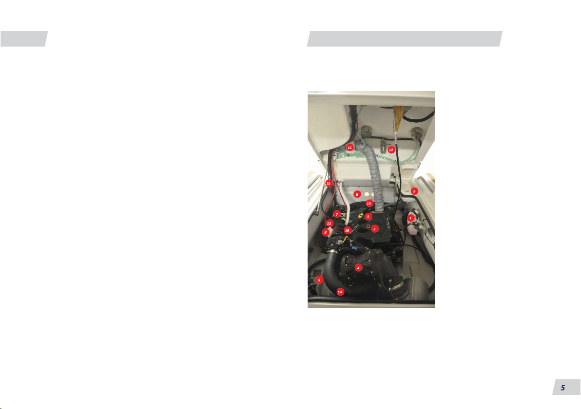
The ABJET® boats are powered by ROTAX® 4-TEC, 4-stroke
engines which are connected to a water jet propulsion system.
DANGER
Indicates a hazardous situation
which, if not avoided, will result in
death or serious injury.
WARNING
Indicates a hazardous situation
which, if not avoided, could result
in death or serious injury.
CAUTION
Indicates a hazardous situation
which, if not avoided, could
result in minor or moderate
personal injury.
NOTICE
Indicates an instruction which,
if not followed, could severely
damage engine components or
other property.

MARINE SAFETY
This Manual is not intended to provide complete training on all
aspects of boat operation. We strongly recommend that all
operators of this boat look for additional information on boat
handling and safety.
We recommend to include the following items:
Anchor & anchor line Mooring lines
Bailer Oars/paddles
Safety requirements differ from country to country, from state
to state and whether you are within coastal waters or inland
waters. For more detailed information, please check with the
local authorities.
The law requires at least one type I, II or III personal flotation
device (PFD) for each person on board or towed on water skis;
and in addition, one throw able type IV PFD. Obtaining PFD´s
and other necessary safety equipment is the owner’s
responsibility.
PFD´s are intended to help you save your own life; you and
your passengers should wear a PFD whenever boating. Many
countries/states require children, age 18 or younger, to wear
PFD´s at all times. It is especially important that children or
non-swimmers wear PFD´s. Make certain you know how to use
PFD´s. Try it on and make adjustment for a comfortable fit.
Show children how to properly put on a PFD.
Batteries
Bellows
Charts
Engine tools
Extra fuel
First aid kit
Flares
Fresh water
Maintenance kit
PFD’s
Portable marine fire extinguisher
Portable radio with weather band
Spare keys
Sunscreen lotion
Tool kit
VHF
Waterproof flashlight
NOTICE
Special PFDs are available for skiing and other water sports.
These PFDs are constructed with materials suitable for high
impact falls into the water.
WARNING
It is a requirement that you carry at least one B-1 type Coast Guard
approved portable marine fire extinguisher on all our models with
prefitted fuel tanks.

KNOWING YOUR ABJET® TENDER
GENERAL ARRANGEMENT
Note:
The following picture is illustrative and may vary
according to the ABJET® model selected.
Boating Terminology
1.
Integrated bow locker
2.
SS davit lifting points
3.
Lateral seat
4.
Fuel filler cap (under seat)
5.
Cup Holders
6.
Digital display gauge
7.
8.
Drain lines with non-return valves
9.
Deck flushing point
10.
Rear seat with ample storage
11.
Push-Push inflation valves
12.
LED anchor light
13.
SS stern ski pole and hand rail
14.
Stern SS foldable cleat
1
Forward
2
Rear
3
Beam
4
Transom
5
Length overall
6
Starboard side
7
Port side
5.
Cup holders
6.
Digital display gauge
7. Shift control
Stern SS foldable cleat
Shift Control

KNOWING YOUR ABJET® TENDER
CONSOLE AND INSTRUMENT PANEL
1
Digital display gauge
2
Control panel mode/set button and toggle
3
Waterproof rocker switches with circuit breakers
4
Engine start/stop button and kill switch
5
Starting ON/OFF key switch
6
Steering wheel
7
Shift Control
8
Battery Switch
Note:
The following picture is illustrative and may vary
according to the ABJET® model chosen.

KNOWING YOUR ABJET® TENDER
ENGINE COMPARTMENT ARRANGEMENT
Note:
The following picture is illustrative and may vary
according to the ABJET® model chosen.
1
Coolant tank
2
Engine oil dipstick
3
Engine oil filler point
4
Engine catalytic converter
5
Towing valve
6
Engine fuse box
7
Main ECU Power Supply Circuit Breaker
8
Battery charger
9
Engine fuel filler
10
Fuel tank
11
Bilge blower
12
Fire extinguisher
13
Battery
14
Bilge pump
15
Console gas springs
16
Engine intake air filter

KNOWING YOUR ABJET® TENDER
JET BOATS SAFETY / IDENTIFICATION NUMBER
Jet Boat Safety
WARNING
An ABJET® may perform differently to other boats you may
have ridden in the past. Take time to familiarize yourself with
your new boat.
Always keep in mind that as the throttle lever is returned to
the idle position, less directional control is available. To turn
the jet boat, both steering and throttle are necessary.
•Boats in general have no brake. Stopping distance will vary
depending on initial speed, load, wind, and water conditions.
Practice stopping and docking in a safe, traffic-free area to get
a sense of how long it will take to stop the boat under varying
conditions.
•
Do not release the throttle when trying to steer away from
objects. You need throttle to steer.
•Do not use the reverse to stop.
•In shallow waters, proceed with caution and at very low
speeds. Grounding or abrupt stops may result in injury to
you, your passengers or others. The jet pump may pick up
debris and throw it forward causing a risk of injuring people
or damaging the jet pump or other property.
•Do not add accessories or equipment that may adversely
affect visibility or alter control of the boat.
•Engine exhaust contains carbon monoxide (CO), which can
cause injury or death if inhaled in sufficient quantities.
Educate all occupants about the risks and symptoms of CO
accumulation and CO poisoning.
•
If, at any time, gasoline leaks/odors are found, do not start
the engine.
Identification Number
Safeguard the information about your boat by recording the
hull identification number (HIN). The HIN is located on the
upper starboard corner of the transom. The HIN must be
clearly visible at all times and must not be removed, altered or
tampered with in any way. The identification number is very
important! Keep a copy of this number stored in a safe place
off the boat in case of theft, damage, warranty claims, etc.,
report this number to the local authorities, your insurance
agent and your dealer.

KNOWING YOUR ABJET® TENDER
ENGINE SPECIFICATIONS
Engine Specifications
OEM with
Engine ROTAX® 4-TEC, 4-stroke.
Number of Cylinders 3
Number of Valves 12
Lubrication Dry sump (2 oil pumps). Replaceable oil filter.
Water-cooled oil cooler.
XPS Synthetic blend oil (summer grade).
Cooling System Closed loop cooling system.
Ethylene-glycol and distilled water (50%/50%).
Exhaust System Water cooled/water injected (opened loop).
Direct flow from jet pump
Jet Pump Axial flow single stage
Fuel Injection Type Multipoint Fuel Injection with intelligent Throttle Control (iTC).
Single Throttle body (60mm) with an integrated actuator.
Fuel Injector 3
Fuel Type Unleaded gasoline
Octane Rating (minimum) Inside North America: 87 (RON+ MON) /2
Fuel outside North America: 92 RON
NOTICE
Never experiment with other fuels. The use of inadequate fuel can result
in boat performance deterioration and damage to critical parts in the fuel
system and engine components.
This Engine is Four Stars -Super Ultra
Low Emission
The four-star label identifies engines that meet the Air
Resources Board’s Stern-drive and Inboard marine engine
2009 exhaust emission standards. Personal Watercraft and
Outboard marine engines may also comply with these
standards. Engines meeting these standards have 90%
lower emissions than One Star – Low Emission engines.
For more information:
Cleaner Watercraft - Get the Facts
1 800 END-SMOG
www.arb.ca.gov

KNOWING YOUR ABJET® TENDER
ABJET® CERTIFICATION
ABJET® Certification
CE Mark
All ABJET®s have been granted the official right to stamp the
CE mark, which means ABJET®s have met all requirements of
the updated Recreational Craft Directive RCD II 2013/53/ EU.
Standard(s) to which conformity is declared:
RCD II Guidelines & ISO 6185-3
Design Category
“C” Inshore: Craft designed for voyages in coastal waters, large
bays, estuaries, lakes and rivers, where conditions up to and
including wind force 6 (Beaufort scale) and significant wave
heights up to and including 2 meters (6,56 ft) may be
experienced.
Manufacturer´s Name: AB MARINE GROUP
Manufacturer’s Address:
Calle 1E N° 2 -15 Bodega N° 9, Zona Franca de Barranquilla,
Colombia. Phone: +57(5) 3795132
Fax: +57(5) 3795667
Certifying Body
HPi Verification Services (Ireland) Ltd
EU Notified Body number: 1521
Clonross, Dunshaughlin, Co., Meath, A85 XN59 Ireland
Web Site: www.hpivs.ie
The CE mark allows us as manufacturers to perform a
declaration of conformity per boat when it is needed. Please
contact us if you need this certification or further information.
MODELS
CERTIFICATION NUMBER
CE CAT
ISO 6185 TYPE
ABJET® 285 &
ABJET® 290
HPiVS-iR1088-T149-I-02-00 CE
HPiUK-R1088-T149-I-02-00 UKCA
C
3
VII
ABJET® 330
HPiVS-iR1088-T143-I-02-00 CE
HPiUK-R1088-T143-I-02-00 UKCA
C
3
VII
ABJET® 350
HPiVS-iR1088-006-I-02-00 CE
HPiUK-R1088-006-I-02-00 UKCA
C
3
VII
ABJET® 380
HPiVS-iR1088-T144-I-02-00 CE
HPiUK-R1088-T144-I-02-00 UKCA
C
3
VII
ABJET® 430
HPiVS-iR1088-T151-I-03-00 CE
HPiUK-R1088-T151-I-03-00 UKCA
C
3
VII
ABJET® 465
HPiVS-iR1088-007-I-02-00 CE
HPiUK
-
R1088
-
007
-
I
-
02
-
00 UKCA
C
3
VII
AB Inflatables as NMMA Member
Means ABJET® has met all requirements to which this boat
in NMMA certified.
Standard(s) to which conformity is declared:
ABYC: American Boat & Yacht council
NMMA: National Marine Manufacturers Association
231 S. La Salle Street. Suite 2050
Chicago, IL60604 U.S.A
Phone: (312) 946-6200
Web site: www.nmma.org

GENERAL DESCRIPTION
The Hull
The bottom of the ABJET® is made out of fiberglass, providing
you with unsurpassable seaworthiness. These boats are
equipped with a marine grade aluminum fuel tank.
CAUTION
Do not drill holes or screw objects in the deck or transom without
sealing the holes. Failure to do so will result in water penetration
and eventually will cause delamination.
WARNING
Do not drill holes in the deck deeper than 1,27 cms (½”).
Otherwise, the tank will be perforated. Trapped gases in the tank
could explode and fuel leaks could occur, which if ignited, may
cause serious injury or death.
The Tube
The buoyancy chamber or tube is “U” shaped with rounded
airtight cones in the same material, ensuring complete safety
and seaworthiness. The ABJET® uses large tubes to increase
payload capabilities and to offer a dry ride. In addition, each
tube is sized proportionately to the boat hull dimensions
which maximizes the internal space.
Inflating Instructions
The inflating system includes the inflation valves and a hand
pump with its valve connector.
The inflation valves:
The inflation valves are plastic and, therefore, non-corrosive
and double sealed for safety. The valve is divided into two
pieces -
one is located on the inner side of the buoyancy chamber and
the other is screwed to the afore. This last piece is
composed of a one-way check valve, a diaphragm and a cap.
This screw-on system enables you to remove and replace a
damaged valve easily.
To Inflate:
Push the end of the bellows hose with the correct valve
connector into place on the valve as far as possible and turn
clockwise until the valve connector locks in place. Compress the
hand pump gently and unhurriedly. When inflated, screw the
plastic cap onto the valve until it is fully seated.
WARNING
Never use a gasoline service station or
a
high compression pump to inflate your
boat. They could damage the buoyancy
collar.

GENERAL DESCRIPTION
Air tightness is obtained partly by means of the plunger one-
way check valve that is set at the base of the valve insert;
complete air tightness is ensured by properly fitting the valve
cap. Before screwing on the cap, check that the valve is clean,
free from sand, weeds or other debris.
To Deflate:
Remove the cap. Push down the spring-loaded plunger in
the center of the valve. To deflate completely, you may
want to lock the plunger down.
The Hand Pump also called Cylindrical Pump:
To inflate the ABJET® boat, plug the valve connector to the
valve. Put it in an upright position and step onto the tongues
located at the bottom of the pump. The hand pump is double
action. Each time you lift and push the handle, 4lts (1 gallon) of
air will enter into the buoyancy chambers. The hand pump
comes with two connectors, one for inflation and the other for
deflation.
The Buoyancy Chambers:
Depending on the model you have chosen, you will have three
or more air chambers. Each chamber is divided by a special
baffle system that keeps the multiple air chambers
completely sealed off from one another, while working to
equalize air pressure between compartments. It is advisable
to inflate your boat properly and check the pressure
frequently. The pressure should be maintained at 0,2 bar (3
Psi) in the buoyancy chambers. (A pressure gauge is not
included with the boat).
A good rule of thumb is: When you cannot deflate the tube
more than 1 cm (3/8”) with the pressure of your finger, you
have then reached the approximate working pressure.
Important:
The correct way to inflate the air chambers is by inflating the
rear chambers first, and then those towards the bow. When
the inflatable buoyancy chambers have been inflated, screw
the cap on the valve properly in order to secure final air
tightness. The buoyancy tubes must be inflated to the
recommended pressure.
NOTICE
The pressure of the boat fluctuates with changes in
temperature.
Pressure increases after prolonged exposure to sun and falls
when the boat is launched and when in darkness. Do not worry
about this.
We have seen experienced people send boats for repair which
were previously in excellent condition due to temperature
fluctuation.
WARNING
Care should be taken not to allow a boat which has been fully
inflated in the cool of the morning to stand in direct sunlight.
Buoyancy pressure will quickly rise with the temperature and
could strain or cause serious damage to the buoyancy tube.
10

GENERAL DESCRIPTION
SEATING ARRANGEMENT / HULL & DECK DRAIN SYSTEM / FUELING AND FUEL SYSTEM
Seating arrangement
Please find all information related to Seating Arrangements
in the Download section at AB Inflatables website:
www.abinflatables.com
Hull & Deck Drain System
Most ABJET®s have a self-bailing deck system which allows
water to flow from the deck to the transom by the action of
gravity; each drain line has a non-return valve to restrict water
to enter the deck when floatation line surpasses the deck level.
Note: If you leave the ABJET® on davits or store it out of
the water, remove the hull drain plug on the transom so
water can drain.
CAUTION
Before launching the boat, make sure that plugs are
secured into the hull drains.
Fueling and Fuel System
All ABJET® boats have a fuel tank installed underneath the
deck. The ABJET® has been designed to allow inspection for
all fuel system components. The system has an electrical
pump located inside the fuel tank, which must not be
removed unless strictly necessary and only by an AB
authorized
service center.
Fuel lines, vent hoses and drain hoses should be checked
frequently for leaks. If leaking occurs, inspect the fuel
system connections. If they are too tight or too loose they
may leak. If upon tightening or loosening the connection the
leak persists, replace the hose. If the hose presents surface
cracking or if it is dry or mushy, replace immediately.
NOTICE
•Take care not to spill gasoline. If gasoline is spilled, use dry rags or
sponges to soak up the fuel and dispose of them properly onshore.
Discharging fuel or oily waste in navigable waters is prohibited. Help
protect our waters.
1
Self-bailing deck drains.
2
Hull drain plug.
3
Over flow fuel drain.
•Make sure you are using the filler pipe marked "Fuel".
WARNING
•Replace with certified marine parts only. Do not use automotive
parts.
•Gasoline is extremely flammable and highly explosive. When
refueling, always turn off the engine. Never smoke or allow open
flames or sparks within 15 meters (50 feet) of the fueling area.
11

GENERAL DESCRIPTION
FUELING AND FUEL SYSTEM / GENERAL SYSTEM ARRANGEMENT / ELECTRICAL SYSTEM OPERATION
•Do not fill tank to capacity. Allow for fuel expansion.
•Do not drill holes in the deck deeper than 1.27 cm (1/2"). Otherwise the fuel
tank will be perforated. Fuel leaks could occur, which if ignited may cause
serious injury or death.
DANGER
•When operating, occupants MUST AVOID standing up or sitting with
their feet hanging over the gunwale.
•Leaking fuel is a fire and explosion hazard. Inspect fuel system
regularly.
WARNING
Fuel is flammable and explosive under certain conditions.
Do not smoke or allow open flames or sparks in the vicinity.
General System Arrangement
The following equipment description includes only the
elements which are installed at the factory as standard
equipment. For any additional information please contact
your local dealer. Each system and its equipment have been
carefully selected and designed to comply with the
requirements set by the ABYC and ISO standards. Also, this
equipment is certified for marine use, which guarantees
durability under the conditions of humidity and salinity of the
marine environment.
Electrical System Operation
The ABJET® is equipped with a 12-volt direct current
electrical system. The positive (+) red large gauge cable is
connected between the (+) battery terminal and the battery
switch. The negative (-) yellow large gauge cable is
connected to a common post ground, where all negative
wires of the boat devices are connected. To start you
r
engine, turn ON the battery switch.
CAUTION
Do not place the battery switch in the off position
while the engine is running.
Breakers and Fuses
Each electrical circuit has been designed to meet the
standards set in ABYC E-11. AB inflatables has made emphasis
on the selection of the circuit protection and
automatic
cutting devices.
12
WARNING
INSPECT SYSTEM FOR LEAKS
AT LEAST ONCE A YEAR.

GENERAL DESCRIPTION
ELECTRICAL SYSTEM OPERATION / STANDARD EQUIPMENT
Breakers
Each of the electrical circuits that feed a certain load are
protected by automatic breakers. These are usually placed
at the switchboard on the console, above the switches of the
circuits it protects. If an overcurrent event happens, the
breaker will act and it will open the circuit to avoid damage
to the wires.
Fuses
The fuses are installed to protect the general circuits (Panel
feed wire/circuit). When an overall damage occurs, the fuse
will burn out and protect the circuit.
NOTICE
See the troubleshooting chart.
Standard Equipment
Boats are delivered with a basic electrical installation.
The standard equipment may vary according to the ABJET®
model acquired.
Bilge Pump
The bilge pump is installed on a flat base located inside the
engine compartment. The function of this device is to
evacuate the water that falls in due to waves, rain or
extreme weather conditions. The owner/user should
remember that ABJET® has a self-bailing deck and rubber
sealed engine compartment. The bilge pump has a dual
operation start system, both automatic and manual. The
pump has the possibility of a remote start by using the manual
switch “BILGE PUMP” installed on the switch board located
on the console. To protect the ABJET® from weather
conditions, this equipment will work even when the “BILGE
PUMP” switch is off; this is possible because the pump is
connected directly to the battery. Thus, the automatic float
system will work even if the user is not there to assist the
evacuation of water. If the bilge pump remains turned on
(continuously working), you must check for any leakage
through the hull or the drain hoses; also check if the
automatic floating switch is stuck.
AMP 1.5
Automatic Bilge Pump
LED Navigation & Anchor Lights
Flushing Point on deck
Automatic Fire Extinguisher Device
Safety Lanyard Switch
Under platform sliding SS Ladder
Engine Compartment
In-Line Blower
Maintenance-Free
Battery
Height Adjustable
Wheel (Tilt)
Mechanical Steering
FUSE (A)
GPH / Oft
NOTICE
3A
500
Battery Switch
System
See the bilge pump installation instructions attached
in your owner manual package.
13

GENERAL DESCRIPTION
STANDARD EQUIPMENT
LED Navigation and Anchor Lights
Standard equipment on all ABJET® tenders includes the
navigation (red/green) light and the anchor (white) light
which work with the NAV/ANC Switch located on the
console switchboard. These lights should be turned on
during the operation of the boat at night. When the boat is
moving, the driver should turn both on, navigation and
anchor light; this is done by pressing the switch to the up
position. When the boat is anchored, the boater should only
turn on the position light by pressing the switch to the low
position. Both lights will be off in the central switch position.
The anchor light consists of a foldable pole with a LED light at
its end. In some models, the navigation (red/green) light is a
small non-foldable pole. To make the lights work, install the
navigation light pole into the plug-in base located at the
bow and the anchor light to the plug-in base behind the rear
seat. Insert the pole matching the pin male orientation to the
plug-in base with the female holes of the pole. The boat
comes with three (3) or four (4) storage clips (depending on the
model) located in the engine compartment, where the pole
lights can be kept while not in use.
Battery Switch
The two-position ON/OFF battery switch is the main ignition
control unit for the boat energy. Through this device the
energy from the battery is transferred to the electrical
systems. When the battery switch is placed in the OFF
position, any device except the bilge pump is de-energized.
The engine, electronic indicators, lights and other
accessories or equipment will operate when the battery
switch is in the ON position. Use the battery switch in the OFF
position in case of fire incidents to cut off the power supply
when an overcurrent event happens and to prevent battery
discharge while the boat is not in use.
14

GENERAL DESCRIPTION
STANDARD EQUIPMENT
Blower
The blower (exhaust fan) is a device installed to draw out the
combustion gases that accumulate in the engine
compartment. This device must be activated prior to starting
the engine in order to avoid accumulation of gases in the
engine compartment. You must run the blower for four (4)
minutes before starting the engine.
Under platform sliding SS Ladder
Folded below the swimming platform for easy stowing, the
convenient Sliding SS Ladder helps you to access the boat from
the water easily and safely.
Automatic Fire Extinguisher Device
This boat is equipped with an automatic fire suppression unit
that contains a highly effective and technologically advanced
fire suppression agent with unique operational characteristics.
This agent has the flow attributes of a gas and has been
determined to be non-toxic to humans when exposed for short
periods of time under certain concentrations.

GENERAL DESCRIPTION
STANDARD EQUIPMENT

GENERAL DESCRIPTION
STANDARD EQUIPMENT
Safety Lanyard
This device is installed next to the key switch on the console.
To run the engine, the lanyard clip must always be attached
to the switch.
The safety lanyard is normally a closed circuit
(complete or active) when the lanyard clip is placed on the
switch. When the lanyard clip is out of the switch, the engine
will automatically shut off to avoid any accident that may
occur.
WARNING
You must secure the lanyard to your wrist or leg, so in case of accidental
overboard fall, the engine shuts off.
Flushing Point on deck
The flushing point fitted on deck will help the operator to
perform the flushing procedure comfortably and easily. The
flushing procedure helps to neutralize the effects of corrosion
by removing sand, salt, and dirt located inside the exhaust
system. For more information please see the After Use section.
Mechanical Steering System
The installed steering system has been specially designed for
jet boats, with a 270° turning arc lock to lock, using a steering
cable with stainless steel inner core and output ends.
Height Adjustable Wheel (Tilt) (Some models)
Depending on the model, ABJET® could include a sport tilt
mechanism to achieve better comfort when handling the
boat, both standing or seating.
Tilt steering delivers unsurpassed performance and flexibility.
This system is precise, allowing for easy turning and its
preloaded dual taper bearings ensure minimal free play at the
wheel.
It offers 48 degrees of tilt articulation and five (5) positive lock
positions.
Maintenance-Free Battery
All ABJET®s contain a 12V, 21 amp-hour high performance
maintenance-free valve regulated lead Battery.
This
battery is completely sealed and non-spillable.
30º
-18º
16
This manual suits for next models
6
Table of contents
Other AB Inflatables Boat manuals